Dynamic Clearance Seal Development from Model Development to Rotating Rig
2018-11-13
(Department of Engineering,Durham University,DH1 3LE,United Kingdom)
Abstract:This paper describes the development of a new sealing concept primarily targeted at steam turbines from concept development to testing in a rotating rig.The seal concept is a development of the spring back gland segment and features a pressurized pocket connected to the upstream face of the sealing segment.By a careful arrangement of the key dimensions of the seal segment a seal is produced that responds to rotor movement that it has a dynamic clearance that responds to rotor movement.This reduces the risk of contact between the rotating and stationary parts in a turbine and allows a lower clearance to be achieved reducing leakage losses.The seal was developed with steam turbine application as the design intent but the dynamic seal idea is a generic one and can be applied to other fields.
Key Words:Tubomachinery,Steam Turbine,Sealing,Dynamic Clearance,Labyrinth,Leakage
1 Introduction
Increased use of renewable energy sources on the electricity grid worldwide in recent years has required conventional fossil fuel plants to operate more flexibly.This work was funded by the“Future Conventional Power Research Consortium”a UK funded project that ran from 2012~2017 and considered the effect of the growth of wind generated power in the power mix on the flexible operating requirements for conventional steam and gas power plant.The increasing amounts of renewable energy present in grids worldwide reduce Co2emissions but they fit into an electrical system designed for fossil fuels in the middle of the last century.Fossil fuels can be turned on and off at will and so are very good at matching variations in load.Renewable energy,which in a United Kingdom context is in the form of wind turbines is much more variable and there is a resultant demand for existing power plants to operate much more flexibly to accommodate the changing power output of renewables as well as the changing demand inherent in the daily electrical cycle.
Generally in order to make a steam turbine more flexible,clearances have to be increased to allow for differential thermal expansions,vibration and transient events that occur during turbine start-up.This has a negative effect on overall steam turbine efficiency due to non-optimal leakage mass flow.A sealing device that can accommodate transient effects is therefore a highly desirable technology for this new operating environment.
2 Classification of Sealing Technology
Seal technology can be classified in a number of ways but in this paper are split into three broad categories,namely:conventional labyrinth seals,brush seals and novel seal designs(such as the one under consideration).
Conventional labyrinth seals consist of a series of knife edge restrictions and have been used in turbomachinery sealing applications for many decades.The seals are deployed in a variety of configurations as shown in Figure 1.The seal works by forcing the leakage flow to accelerate rapidly under the restriction which decreases the static pressure of the fluid.Some of the kinetic energy is then dissipated by viscous effects in the mixing that takes place following the restriction so that not all of the static pressure is recovered upon deceleration of the fluid in the cavity.On straight labyrinth seals there is a danger that the high velocity jet that forms under the first restriction may continue under the subsequent restriction.Hence stepped and staggered labyrinth seal types typically work better.
There has been a great deal of research into how geometrical effects of the teeth can change the leakage characteristics of such a seal,such as fin pitch as reported by Li et al(2006).[1]Other authors have investigated many aspects of labyrinth seals and one example is Gamal and Vance(2008)[2]who investigated the effect of tooth shape and seal eccentricity.
An important variant of the conventional labyrinth seal is the retractable(or spring backed)gland.This has circum-ferential springs between the gland segments,which push them apart,and generate a large radial clearance with the rotor before start-up.This retracted position allows the rotor to pass through a natural frequency during run-up without rotor contact as the turbine is usually run up to full speed before full operating pressure is reached.As the turbine is loaded the pressure gradient across the gland builds and the segments move in radially.The segments come to rest on shoulders,which are positioned to achieve a certain clearance with the rotor usually of the order of 0.7mm.It is a development of this seal that is the subject of the present paper.
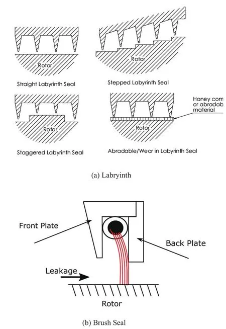
Fig.1 Existing sealing technology
The main advantages of the labyrinth seal are its simplicity.The disadvantages of the seal are the relatively high leakage compared to more advanced seals,and that the seal can only withstand small rotor excursions without suffering damage which increases the leakage through the seal.The retractable gland goes some way to protect the seal from damage during rotor start-up.
Brush seals are the first alternative to labyrinth seals that have produced extensive performance benefits and are in widespread service Chupp et.al.(2006)[3].Brush seals have enabled up to 80%leakage reduction over a conventional labyrinth seal Dinc et.al.(2002)[4],as well as more stable leakage characteristics,better accommodation of shaft movements and they also require less axial space than labyrinth seals.
Brush seals are made from fine diameter bristles layered together to make a dense pack.The bristles are radially angled with the shaft rotational direction by approximately 50 degrees to accommodate rotor radius changes without the bristles buckling.The bristles are held between two rings and typically have a slight interference fit to the rotor.Figure 1 shows the configuration of a typical brush seal.Brush seal performance will deteriorate over time due to wear of the bristles and the seal can also cause localized heating due to the rubbing of the bristles on the rotor.The main advantages of the brush seal are the improved performance compared to labyrinth seals.The disadvantages of the seal are the relatively high cost of manufacture and the degradation of performance over time.
The third type of seal technology under consideration are so called“novel technologies”.These sealing types typically operate using quite different techniques from existing sealing technologies and have(at the time of writing)limited service experience compared to more established techniques.As well as the subject of the current paper two other sealing types in this category are the“halo”seal and fluidic curtain type seals.The“hydro-static advanced low leakage”(halo)seal is a non-contacting all metal compliant seal that is designed for self-controlling clearance.The seal consists of cantilevered pads that are able to move towards and away from the rotor,held by radial soft and axial stiff springs.A downstream secondary seal is used to prevent leakage through the cantilever spring section.Hydrodynamic and hydro-static forces are used to achieve radial equilibrium with the seal shoe floating on a thin fluid film.The halo seal has been demonstrated to reduce leakage mass flow rate by up to 70%at high pressure ratios in a high temperature rotating seal rig(San Andrés et.al.(2014))[5].
Fluidic seals use aerodynamic flow effects with the aim to create additional losses and hence reduce the leakage flow.This is achieved by the use of a continuous air curtain in the leakage cavity,often combined with labyrinth fins or other restrictions(Curtis et.al.(2009))[6].Advantages of this type of seal are that they are non-contacting,are insensitive to relative movement between components and do not degrade with machine life.Further developments of the fluidic curtain idea in the authors’institution are described by Hilfer et.al.(2015)[7].
3 The Dynamic Seal Concept
The aerostatic gland concept(Seaton(2014))[8]works on the same principle as an aerostatic bearing in which increased pressure is experienced as the gland segment approaches the rotor.Due to the ability of the gland to respond to rotor movements,the gland design clearance can be reduced since the gland will accommodate rotor excursions and thermal growth.
The basic operation of the concept is shown in Figure 2,although not all the details are included.The fundamental mechanism for the aerostatic seal to move away or towards the rotor is provided by the pressure difference between the top and bottom of the seal segment.
The left hand image in Figure 2,shows the axial pres-sure distribution expected at a high clearance both on top and underneath the seal.The area between the top pressure and the bottom pressure on the graph represents the radial force per unit length of seal in the radial direction(ignoring pressure on the side of the seal segment and seal curvature).At high clearances the leakage area underneath the seal is much greater than the feed hole area,and so the mass flow rate going through the feed holes is small in comparison to the main leakage flow underneath the seal.Therefore the pressure distribution is similar to a normal labyrinth seal.Since the pressure loss in the axial direction is evenly distributed there is a net radial force towards the rotor.
The right hand image in Figure2,shows the same graph of axial pressure distribution.But this time at a lower clearance,the area of the main leakage path is much reduced,and so a much larger proportion of the leakage flow travels through the feed holes.Since the pressure drop across a labyrinth fin depends on the mass flow going through the seal,the pressure loss at the first two fins is much reduced.This has the effect of decreasing the radial force pushing the gland segment towards the rotor(shown on the graph by a reduced area),and so there is a net radial force pushing the seal away from the rotor.As before the net radial force has to be large enough to overcome the static friction force before the gland can move.
The net result is that by careful choice of the size and shape of the gland segment a seal that responds to rotor movement can be designed.
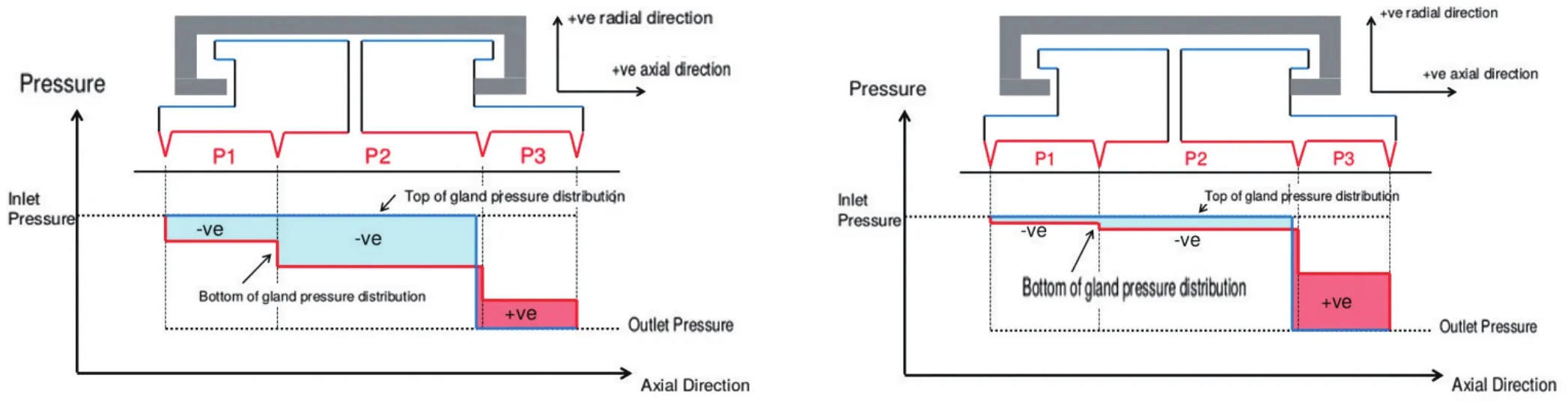
Fig.2 The dynamic seal concept
4 Development of The Dynamic Clearance Seal
Users of steam turbines demand high performance and high reliability and the remainder of this paper describes how the concept outlined above was developed into a design that could be tested at realistic steam conditions prior to prototype introduction.Although the reality of a development project is much more complex the work can be split into what are essentially four phases:(I)Numerical modeling of the design to come up with candidate geometries using reduced order models,(II)A static test rig which demonstrated the force vs clearance behavior without the expense or complexity of rotating elements,(III)A rotating test rig operating on air at ambient temperature to demonstrate the operation of the technology at the correct non-dimensional parameters and(IV)A test using steam at conditions that the seal would experience in operational service.
5 Numerical Modeling(Phase I)
After the concept had been established the first modeling was carried out to determine if the idea could be plausibly taken further.This work used a bespoke reduced order model using MATLAB validated and backed up by RANS CFD.The work was carried out by Auld(2011)[9]and produced the first quantification of the performance of the aerostatic seal,the analysis was all conducted on a 2D slice of the gland segment using a force balance on the gland and 1D models of fluid flow behavior.Seal behavior was adjusted by altering the dimensions of the seal shown in Figure 3.The analysis showed that the idea had potential but the range of designs that could be produced seemed to be rather limited due to limitations on achieving moment stability.However further analysis work was continued by Rafferty(2012)[10]who showed(using Auld’s design tools)that when the full arc of the seal is included in the analysis the number of potential designs that can operated successfully increases considerably.A key variable identified during the modeling was the coefficient of friction of the gland and the gland holder.
The numerical modeling(conducted at extremely modest cost)gave enough confidence to move to experimental verification of the idea.
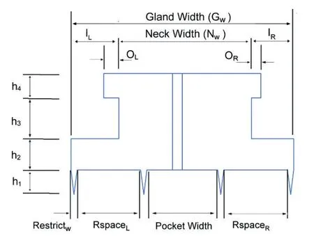
Fig.3 Cross-sectional dimensions adjusted during design iterations.(Rafferty 2012)[10]
6 Static Testing(Phase II)
Through the development of this seal design the intention has been to advance the design step by step to reduce the risk of large amounts of time and effort being sunk into a device that has been shown to be non-viable.In Phase II of the work an experiment was planned to show the concept working and validate the reduced order modeling that had been carried out.Two major simplifications were used in the experiment:firstly the use of air rather than steam as the test medium as this reduced the complexity of the experimental rig required and secondly the rotor position was fixed,instead the dynamic performance of the seal was demonstrated using a variable pressure ratio.This required the design tools to be revised to use air and not steam as the working medium before work could commence.
A simple test rig was built to test the seal behavior of which a half section is shown on the left in Figure 4,this rig was equipped with a number of displacement sensors and the primary means of controlling it was to adjust the pressure ratio across the rig.This allowed transient behavior to be observed in a rig without rotation.The test results which are detailed in(Messenger at al 2015)[11]but the key result is shown on the right hand side of Figure 4 and showed that the clearance of the seal changed with pressure ratio and a successful demonstration of the concept in the laboratory was observed.
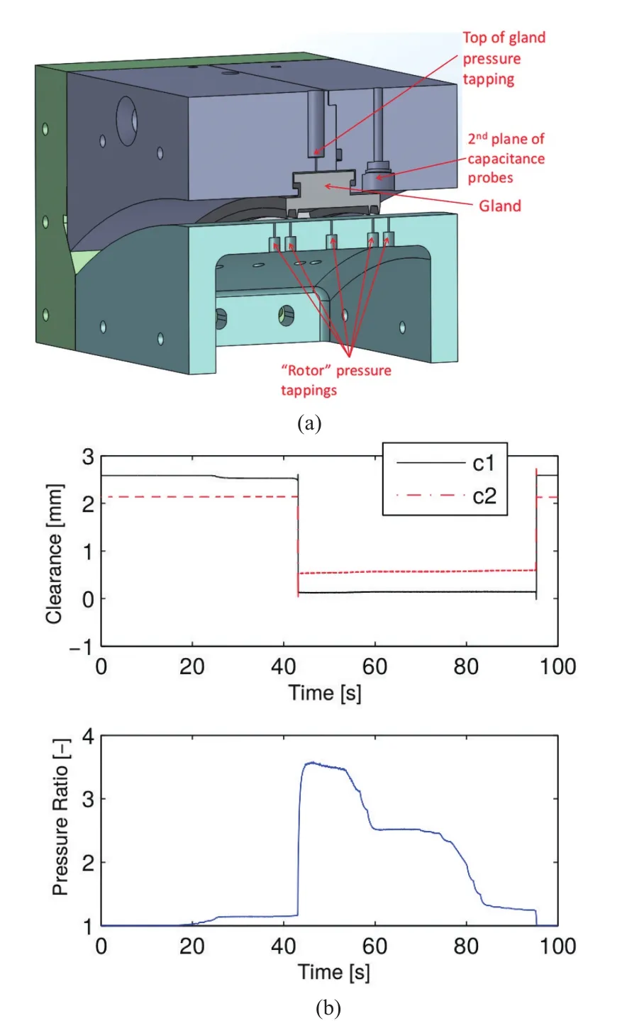
Fig.4 Static test rig(a)and initial dynamic results(b).
Further testing was carried out on the rig and full details can be found in Messenger et.al.(2016)[12]but the main finding was demonstration of the key functional mode of the aerostatic seal.That is the gland segment was shown to move away from the rotor when at a low clearance and move towards the rotor when at a high clearance.
The work of Messenger et.al.(2016)[12]showed that the analytical tools used to design the seals captured the main behavior of the seal,but there were still some discrepancies which needed to be addressed for further development.These were i)a sensitivity to small pressure variations in key locations and ii)the modeling of the flow around the side of the gland segment which was quite simplistic in the original design tool.Finally the testing revealed that the variation in actual friction coefficient can have a large effect on the final gland clearance achieved which was expected from the modeling results in Phase I.
7 Rotating Rig Testing In Air(Phase III)
The results of the static testing in Phase II gave enough confidence to build a rotating rig to demonstrate the dynamic response of the seal a cross section is shown in Figure 5.The working medium was chosen as air as this substantially reduced the complexity of the rig and allowed a far more detailed set of instrumentation to be applied to the rig than would have been possible with steam.
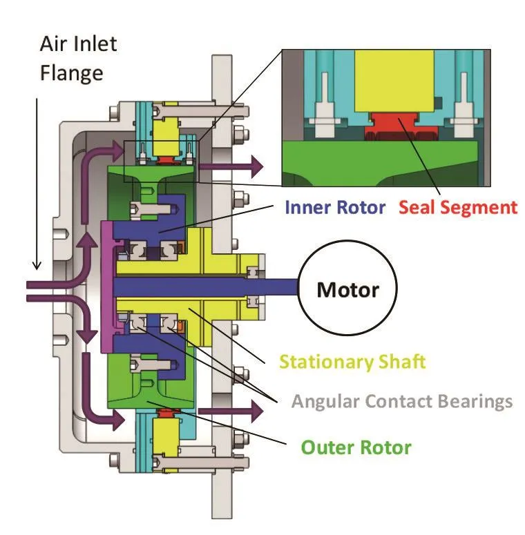
Fig.5 Cross section of durham rotating seals rig
The facility consisted of a rotor mounted on a cantilevered stub shaft,and was a‘single flow’arrangement.A pair of high capacity angular contact bearings resisted the axial load due to the seal pressure difference.The rotor was driven by a smaller inner shaft connected to the motor through a flexible coupling.The rotor has been manufactured as an inner rotor connected to the bearings and an outer rotor which can be positioned off center to achieve rotor eccentricity.Although the two parts of the rotor were bolted together,two sets of dowls are also included which consistently position the outer rotor section in a low eccentricity position(0.09 mm),or a high eccentricity position(0.55 mm).
Inlet static pressure and temperature were measured,as well as the outlet static pressure and mass flow rate of air through the rig.There are six outlets from the rig to atmosphere,each one situated directly behind each seal segment.This allowed the use of a camera to observe seal segment behavior.
Testing was conducted with the rotor in two positions:low eccentricity(0.09 mm)and high eccentricity(0.55 mm).The aim of the low eccentricity testing was to demonstrate Aerostatic Seal performance at similar levels of eccentricity found in a running turbine.High eccentricity testing was conducted to assess how responsive the Aerostatic Seal was to more extreme rotor radial transients,and to demonstrate the ability of the seal to move away from the rotor without metal on metal contact.A final set of tests were conducted with the seal segments fixed at a known position and the feed holes blocked.This provided an equivalent labyrinth seal to assess the leakage reduction of the Aerostatic Seal.Full details of the test campaign can be found in Messenger at.al.(2017)[13]but the key results are discussed here.
Figure 6 shows the dynamic response of the seal using the top segment and the high eccentricity as an illustrative example.The seal segment position sensors were calibrated to give seal segment position relative to mean rotor surface position.However since the seal segment position sensors were not positioned at the same circumferential position as the rotor surface sensors the seal segment position was time shifted to reflect the different rotor position at different circumferential positions in Figure 6 which illustrates that the seal successfully responds to the rotor movement.
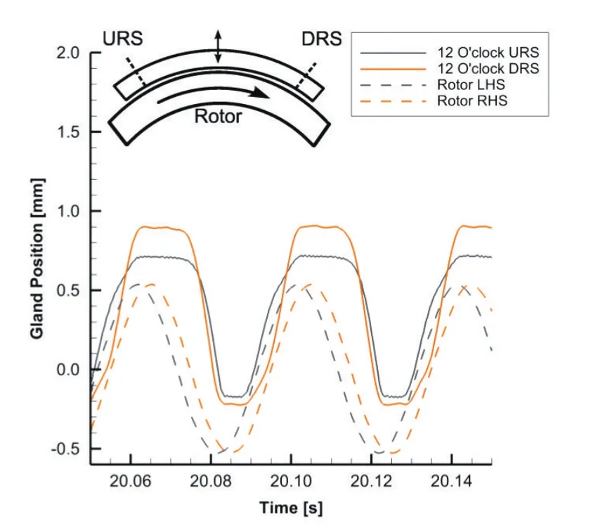
Fig.6 Seal segment response at 1500 RPM with high eccentricity
To assess the potential leakage reduction the Aerostatic Seal delivered over a comparable labyrinth seal,the Aerostatic Seal segments were fixed in position to provide a fixed conventional labyrinth seal for comparison.Alongside this experiment a number of analytical published methods for calculating labyrinth seal performance were also used to calculate the expected performance of this labyrinth seal.These results are shown in Figure 7 and show that the measured conventional seal performance(black circles)matches up well with the various analytical methods giving confidence in the overall test results.A variety of results from the aerostatic seal are also shown in the figure and illustrate and substantial leakage reduction over a range of different operating conditions.At the design pressure ratio a leakage reduction of 30%compared to the fixed design is a reasonable estimate of the performance gains.
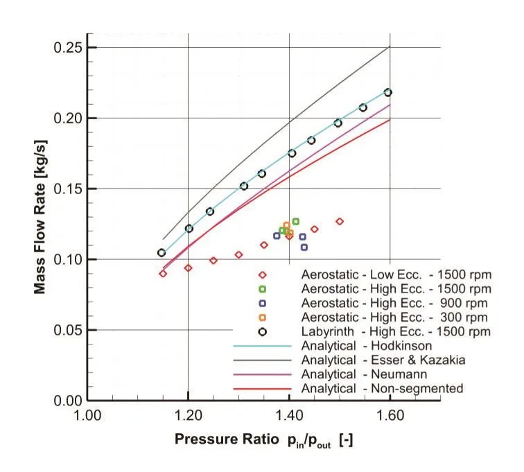
Fig.7 Leakage mass flow rate
One notable feature of the aerostatic seal to highlight is that the tests conducted with a high level of rotor eccentricity showed that the seal was able to maintain a mean clearance that was smaller than the level of rotor eccentricity over the full range of rotor speeds tested.A typical labyrinth seal or retractable seal is simple unable to do this and this finding is a key indicator of the potential benefits of the new technology.
8 Steam Testing(Phase IV)
Following the successful results found in Phase III,the design tool for the seal was adjusted to bring steam properties back into the calculation.A seal design was developed for a seals test rig located at TU Braunschweig in Germany.High pressure and temperature steam is supplied to the facility from a power station boiler,and so the facility replicates steam turbine steam conditions.The rotor can operate up to 10 000 rpm to match steam turbine rotor surface speed.
The test facility is constructed in a double flow arrangement with the high pressure steam entering the high pressure chamber in the centre,and flowing outwards through two seals under test.Each side was referred to as the“motor side”and the“displacement side”.The rotor diameter is 300 mm,and so is roughly half that of a typical power generation steam turbine.The facility also has the ability to translate the high pressure casing relative to the rotor to simulate low speed rotor excursions,achieved by heating or cooling the facility support structure.Full details on the facility and its capability can be found in previously published works such as(Raben 2013)[14].
The key objective of the testing was to show operation of the Aerostatic Gland in a steam environment,and this was achieved by showing the seal reducing clearance as the pressure difference was increased,and also showing that the seal was able to respond to the rotor translation.
The mass flow rate and pressure difference of the motor side seal for a 60 minute time period is shown in Figure 8.Initially the mass flow rate and pressure drop across the seal was low at the seal segment were in the retracted position.Note that the traces shown in Figure 8.have been smoothed with a moving average to remove noise from the signals.The outlet pressure was constant throughout the test at 3.0 bar(g),and the inlet steam temperature around 400°C.From 18:05 the inlet steam valve was opened slowly which increases the mass flow rate through the seal.At 18:35 the seal segments close in,causing a large increase in the pressure difference across the seal.The leakage through the seal depends on the leakage area of the seal,the pressure ratio across the seal,and the fluid density.Therefore despite the seal segment moving towards the rotor and reducing the leakage area of the seal,the mass flow remains virtually the same as the pressure ratio across the seal has increased.The mass flow rate reduces as the inlet pressure was reduced.
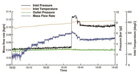
Fig.8 Mass flow rate,pressure and temperature of motor side seal
Overall testing the Aerostatic Seal in a steam environment was completed successfully,and the seal exhibited dynamic characteristics.
9 Conclusions
A dynamic seal design for steam turbine application has been developed and is ready for a test deployment in a real steam turbine.The seal is a modification of existing spring backed gland segments in current use.The modification consists of a pressurized pocket in the center of a conventional labyrinth seal arrangement and by a careful choice of seal dimensions can be made to give a dynamic response.This response allows a much lower operating clearance to be obtained and so reduces the leakage flow by around 30%.
The novel seal design has been developed through a series of numerical and experimental models of increasing complexity(MATLAB modeling,static test rig in air,rotating test rig in air and rotating steam conditions)to build confidence at each stage in the development before committing to the increased complexity and cost of higher fidelity modeling.This approach has the advantage of a low risk but the trade off is that the seal technology takes longer to mature than if a concurrent approach to development had been developed.
Acknowledgements
This work was supported by the Engineering and Physical Sciences Research Council[grant number EP/K02115X/1]and GE Power.The authors also acknowledge the significant contributions of Jon Seaton,Stacie Tibos and Bernard Charnley from GE Power to the work but the responsibility for any errors and omissions in the work rests with the authors.