A Mode-Switching Motion Control System for Reactive Interaction and Surface Following Using Industrial Robots
2018-08-11DanialNakhaeiniaPierrePayeurandRobertLaganire
Danial Nakhaeinia,Pierre Payeur,and Robert Laganière
Abstract—This work proposes a sensor-based control system for fully automated object detection and exploration(surface following)with a redundant industrial robot.The control system utilizes both off line and online trajectory planning for reactive interaction with objects of different shapes and color using RGBD vision and proximity/contact sensors feedback where no prior knowledge of the objects is available.The RGB-D sensor is used to collect raw 3D information of the environment.The data is then processed to segment an object of interest in the scene.In order to completely explore the object,a coverage path planning technique is proposed using a dynamic 3D occupancy grid method to generate a primary(off line)trajectory.However,RGB-D sensors are very sensitive to lighting and provide only limited accuracy on the depth measurements.Therefore,the coverage path planning is then further assisted by a real-time adaptive path planning using a fuzzy self-tuning proportional integral derivative(PID)controller.The latter allows the robot to dynamically update the 3D model by a specially designed instrumented compliant wrist and adapt to the surfaces it approaches or touches.A modes witching scheme is also proposed to efficiently integrate and smoothly switch between the interaction modes under certain conditions.Experimental results using a CRS-F3 manipulator equipped with a custom-built compliant wrist demonstrate the feasibility and performance of the proposed method.
I.INTRODUCTION
SENSOR-BASED control in robotics can contribute to the ever growing industrial demand to improve speed and precision,especially in an uncalibrated working environment.But beside the kinematic capabilities of common industrial robots,the sensing abilities are still underdeveloped.Force sensors are mainly used in the context of the classical constrained hybrid force/position control[1]−[3]where force control is added for tasks that involve dealing with contact on surfaces.Tactile sensors determine different physical properties of objects and allow the assessment of object properties such as deformation,shape,surface normal,curvature measurement,and slip detection through their contact with the world[4],[5].However,these sensors are only applicable where prior knowledge of the environment is available and there is a physical interaction between the robot and objects.In addition,the execution speed of the task is limited due to the limited bandwidth of the sensors,and to prevent loss of contact and information some planned trajectories must be prescribed[6].
Using vision sensors in order to control a robot is commonly called visual servoing where visual features such as points,lines and regions are used in various object manipulation tasks such as alignment of a robot manipulator with an object[7].In contrast to force/tactile control,vision-based control systems require no contact with the object,allow non-contact measurement of the environment and do not need geometric models.The vision measurement is usually combined with force/tactile measurement as hybrid visual/force control[8],[9]for further manipulation.3D profiling cameras,scanners,sonars or combinations of them have been used for manipulation of objects,which often result in lengthy acquisition and slow processing of massive amounts of information[10].An alternative to obtain 3D data is replacing the high-cost sensors by an affordable Kinect sensor[11],[12].The Kinect technology is used to rapidly acquire RGB-D data over the surface of objects.
Beyond selecting proper sensors,reliable interaction control strategy and reactive planning algorithms are required to direct the robot motion under consideration of the kinematic constraints and environment uncertainties[13].Although conventional proportional derivative/proportional integral derivative(PD/PID)controllers are the most applicable controller for robot manipulators,they are not suitable for nonlinear systems and lack robustness to disturbances and uncertainties.A general solution to this problem is to design and develop adaptive controllers where adaptive laws are devised based on the kinematics and dynamic models of the robot systems[14].Furthermore,to achieve a better performance and smoothly switch between different motion modes,switched control systems were proposed[15]to dictate switching law and determine which motion mode(s)should be active.
Aiming at bringing dexterous manipulation at a higher level of performance,dexterity and operational capabilities,this work proposes a unique mode-switching motion control system.It details the development of a dexterous manipulation framework and algorithms using a specially designed compliant wrist for complete exploration and live surface following of objects with arbitrary surface shapes endowed with adaptive motion planning and control approach coupled with vision,proximity and contact sensing.
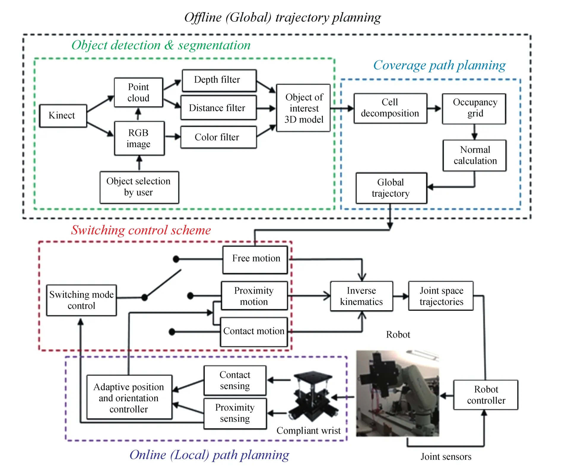
Fig.1.Block diagram of the proposed mode switching control system.
In order to enable industrial robots to interact with the environment smoothly and flexibly,adaptable compliance should be incorporated to industrial robots.A review of the traditional and recent robotics technologies shows that in many cases the modifications are technically challenging,not feasible and require hardware modifications,retro fitting,and new components which result in high costs.In this work,the flexibility problem is addressed by using a low cost specially designed compliant wrist mounted on the robot end-effector to increase the robot mechanical compliance and reduce the risk of damages.In contrast to other works,the adaptive controllers solve the force control problem in form of a position control problem where infrared sensors provide the required information for the interaction instead of touch sensors(force/torque,tactile and haptic).The proposed adaptive controllers require no learning procedure,no precise mathematical model of the robot and the environment and do not rely on force/torque calculation.As such the controllers enable the robot to interact with objects with and without contact.
The paper is organized as follows:Section II gives an overview of the control system design.Section III presents the off line trajectory planning,and Section IV details the design of the online proximity and contact path planning.Section V describes the proposed switching scheme.Experimental results are presented in Section VI,and a final discussion concludes the paper in Section VII.
II.MODE-SWITCHING MOTION CONTROL SYSTEM OVERVIEW
The robotic interaction with objects or surface following problem consists of a complete exploration and alignment of a robot’s end-effector with a surface while accommodating its location and curvature.This work proposes a switched control approach for fast and accurate interaction with objects of different shapes and colors.In order to guide the robot’s end-effector towards the surface,and then control its motion to execute the desired interaction with the surface,the problem is divided into 3 stages of free,proximity and contact motion.Each of the three control modes uses a specific sensory information to guide the robot in different regions of the workspace.
The main components and interconnections,as well as how they interact with each other are shown in Fig.1.
The first step to achieve interaction with an object is the detection and localization of that object in the robot workspace.For that matter,a Kinect sensor is used for rapidly acquiring color and 3D data of the environment and to generate a primary(of fline)trajectory as a general guidance for navigation and interaction with the object(free motion mode).The proximity control and contact control modes are also designed and integrated to the system.They dynamically update the 3D model through using a specially designed instrumented compliant wrist and modify the position and orientation of the robot based on the online sensory information when it is in close proximity(proximity interaction)and in contact with the object(contact interaction).The following sections detail the design and implementation of the system and its main components.
III.OFFLINE(FREE MOTION)TRAJECTORY PLANNING
In the free motion phase,which refers to the robot movement in an unconstrained workspace,a 3D model of the object of interest is constructed using 3D data collected by a Kinect sensor.For that matter,the Kinect sensor is positioned behind the robot with its viewing axis pointing towards the surface of the object for collecting data over the object as shown in Fig.2.Based on the surface shape acquired by this peripheral vision stage,a unique coverage path planning(CPP)strategy is developed using a dynamic 3D occupancy grid to plan a global trajectory and support the early robotic exploration stage of the object’s surface.
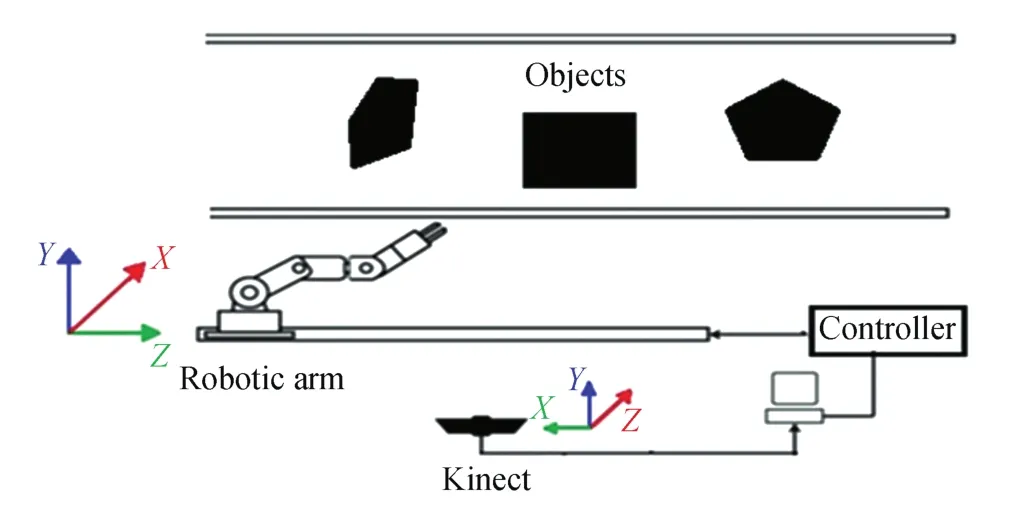
Fig.2.The RGB-D sensor positioning.
A.Object Detection and Segmentation
In order to efficiently navigate a robotic manipulator and interact with objects of various shapes,identification and localization of the object of interest in the robot workspace must first be achieved.For that matter,a Kinect sensor is used to acquire RGB images of the workspace along with depth information.When multiple objects are present in the working environment,objects of interest must be identified and discriminated from the scene.Three filters are used to extract and segment an object of interest from the workspace:a depth filter,a color filter and a distance filter.The data acquired by the Kinect sensor contains an RGB image and a collection of vertices(Point Cloud).Each point,pi,with(x,y,z)coordinates is defined with respect to the Kinect(K)reference frame and supports corresponding(r,g,b)color values,defined as follows:


where v is the number of vertices in the point cloud.The depth of field covered by the Kinect sensor is typically between 0.5m to 6m and the error in depth considerably rises with the distance[16].Therefore,the noisy background is discarded and the maximum depth range is limited to that of the robot workspace.To filter out the vertices that are not in the desired depth range(Dz),a thresholding filter is applied(see Algorithm 1)which eliminates all the vertices with a depth value(Z-coordinate)over a pre-set desired range(Fig.3).
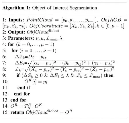

Fig.3.Depth filter:(a)original data from Kinect,(b)after applying the depth filter.
In order to optimize the robot movement,the desired object information should be extracted from the RGB-D data using color and distance segmentation.After acquiring the data,the RGB image(Fig.4(a))is presented to the operator.A mouse event callback function waits for the operator to click on any points of the desired object and returns the RGB-D values of the corresponding pixels.The RGB values of the points selected over the desired object(Fig.4(b))are used as a filter for the color segmentation.To increase the accuracy of the color segmentation,the operator can choose a number of points(µ)over the object surface according to the object’s size and shape.The RGB values of the operator selected points of interest(2)are used to define a range of color for the object of interest.The vertices in the RGB image that are within the same color range and for which the Euclidean color distance(∆E)is less than a specific pre-set threshold(λ)are extracted from the point cloud,while the other vertices are eliminated.


Fig.4.(a)RGB image of the working environment,and(b)RGB values related to the selected points over the object of interest(the white square board).
The color segmentation allows to group parts of similar color.However,if there are multiple objects of similar color in the scene,a single object of interest cannot be identified only using color segmentation.Therefore,a distance filter is also applied on the point cloud to extract only the object of interest.Since each pixel in the RGB image corresponds to a particular point in the RGB-D point cloud,a primary estimate of the object of interest’s position(3)in the workspace is extracted from the vertices corresponding to the points selected by the operator.By clicking on points respectively close to the corners and to the center of the object of interest,the maximum distance(£max)between the center and the corners is calculated by(4).Then,the distance between each vertex in the point cloud and the center point(£)selected by the user is compared with the maximum distance(£max)and the vertices for which that distance is higher than£maxare dropped.

where[Xc,Yc,Zc]are the coordinates of the object center andµis the number of selected points by the operator.This filter ensures that objects sharing similar color will be segmented individually,unless they overlap in space.
Eventually,the remaining set of m vertices(Oi)forms the object of interest RGB-D point cloud(5).However,the vertices are defined with respect to the Kinect reference frame and must be transformed to the robot’s(R)base frame(6)

B.Coverage Path Planning
The key task of coverage path planning(CPP)is to guide the robot over the object surface and guarantee a complete coverage using the preprocessed RGB-D data.The proposed CPP is developed using the dynamic 3D occupancy grid method.The occupancy grid is constant when the environment(object)is static.In most of the previously proposed methods,the occupancy grid is built in an off line phase and it is not updated during operation,which requires very accurate localization.However,in the proposed method the occupancy grid is initially formed using the information provided by the Kinect sensor and it is dynamically refined during interaction using the data acquired by proximity sensors embedded in the compliant wrist mounted on the robot.
1)Occupancy Grid
As shown in Fig.5(a),once the object of interest is identified and modeled in 3D,the object surface is discretized to a set of uniform cubic cells(7).The resolution of the occupancy grid is adapted according to the volume of the object of interest:
(Zmax−Zmin)mm×(Xmax−Xmin)mm×(Ymax−Ymin)mm where Ymin,Ymax,Xmin,Xmax,Zminand Zmaxcorrespond respectively to the minimum and maximum values of the Y,X and Z coordinates in the point cloud of the object of interest.Size of the cells can be selected based on the end-effector size or the desired resolution of the grid for a particular application.Therefore,initially the object of interest is mapped into an occupancy grid with cube cells of the same size as the robot’s tool plate size,in the present case 130mm×130mm×130mm.
The major issue arises when cells are partially occupied.That usually happens where the object has acute edges and also near the borders of the object of interest.

where CI,J,Krepresents a cell in the object model and

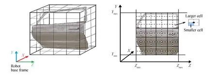
Fig.5.(a)Object of interest 3D model,and(b)object discretized to a set of uniform cubic cells.
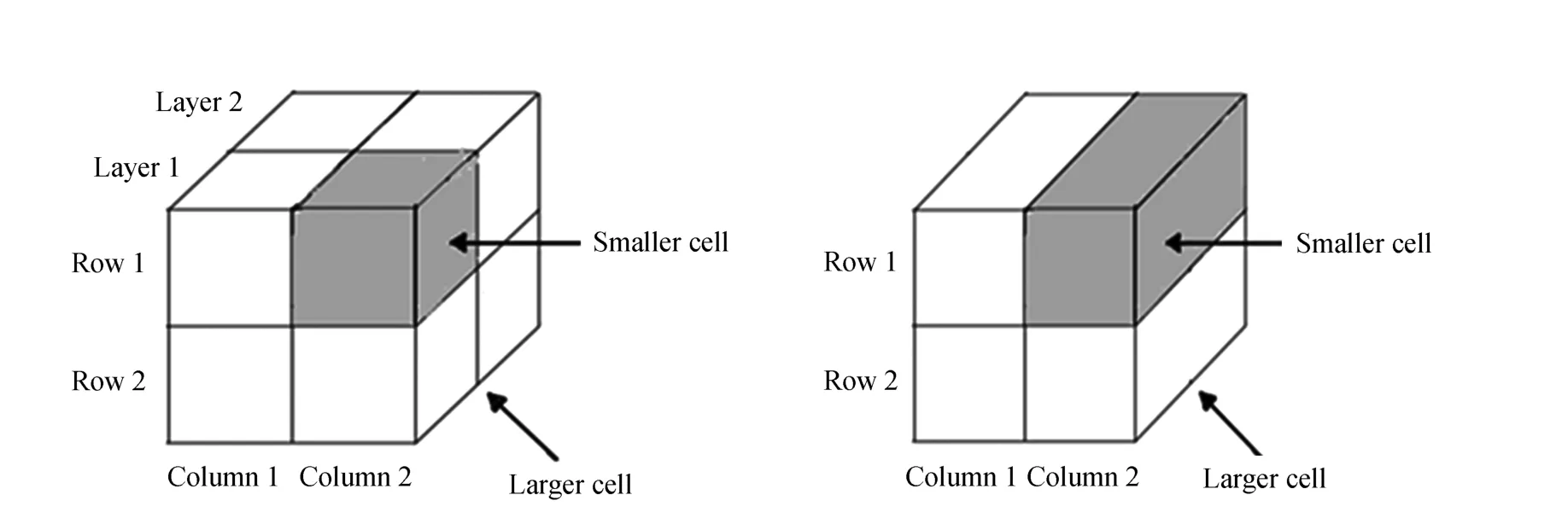
Fig.6.(a)Smaller cell and larger cell representation,and(b)merging smaller cell to reduce data volume.
In order to solve the problem,the grid resolution is increased and two different cells(larger and smaller)sizes are used(Fig.5(b)).The smaller cells(Cs)are cubes with size of 65mm×65mm×65mm with each larger cell(CB)containing 8 smaller cells in two layers of four(Fig.6(a)).Another problem with 3D occupancy grids is that they require large memory space,especially when fine resolution is required[18].Considering that the RGB-D sensor is perceiving the scene from a point of view that is perpendicular to the surface of the object,the regions in the back are essentially occluded.Therefore,to achieve computational efficiency and decrease complexity and the number of cells,the front and back layers of the larger cells are merged into one layer and the smaller cells are replaced with cuboid cells of size 65mm×65mm×130mm(Fig.6(b)),leading to a 2.5D occupancy grid model.The occupancy grid is formed by determining the state of each cell.The smaller cellsare classified with two states as occupied or free.A cell is called occupied if there exist at least some vertices in the cell.If the smaller cell is occupied,the cell value is 1,otherwise it is 0.The state variables associated with the larger cellsare:occupied,unknown and free which are identified based on the smaller cell’s value.If more than two smaller cells of a larger cell are occupied,the value of the associated larger cell is 1,else if one or two of the small cells are occupied the value is 0.5,and if all the small cells are free then it is 0(9).The occupancy grid corresponding to the larger cells is represented by a H×V×P matrix(10).Initially all cells are considered as unknown.Therefore,the occupancy matrix,OccMatrix is initialized with a value equal to 0.5 wherecontains occupancy information associated with the larger cell(I,J,K)and cell(0,0,0)is located in the upper left corner of the grid.

OccMatrix

The occupancy matrix provides the required information to plan an off line trajectory to explore the object surface.Therefore,in the next step the occupancy matrix is used for global path planning.In addition,to preserve the dynamic characteristic of the occupancy grid and achieve a more accurate and efficient exploration,the occupancy grid will be updated using extra sensory information when the robot is in close proximity of the object.
2)Global Trajectory Generation
In order to explore the object completely and optimize the trajectory,the robot should explore all the occupied cells and avoid the free ones.The robot’s end-effector pose at each time step is defined by a set of points:

TrajectoryGlobal

where occ is the number of occupied cells in the occupancy grid.
In this work,the start point is always the first occupied cell on the front upper row of the occupancy grid and the initial moving direction is horizontal.The robot position at each moving step(posG[k])is defined by extracting the closest point in the object point cloud(ObjCloudRobot)to the center of the occupied larger cell(centre)in the robot moving direction.However,if the larger cell is not completely occupied(=0.5)the posG(k)is determined based on the new measurements from the proximity sensors(detailed in Section IV-B).As shown in Fig.7(a),the robot can move in 5 directions[horizontally(left/right),vertically down,and diagonally(left/right)down]and it must move through all the points to cover the target area.The target area is covered using a zigzag(Fig.7(b))pattern which is also called Seed Spreader motion[19].The robot begins from a start point and moves horizontally to the right towards the center of the next occupied cell.If there is no occupied cell on the right,the motion direction is changed and the robot moves vertically(diagonally)down to the next point.Then,the robot again moves horizontally but in the opposite direction until it reaches the last occupied cell on the other side of the object.The process continues until the robot has explored the entire area.

Fig.7.(a)Accessible directions of motion,(b)global trajectory planning to ensure coverage,and(c)vertex normal calculation at the center of a larger cell.
The set of points forming a path for the robot defined in the previous step determines the positions for the end-effector in Cartesian coordinates over the object surface.In addition to the robot position,to ensure proper alignment of the end-effector with the surface,it is required to estimate the surface normal and calculate the end-effector orientation at each point.The local normal at each point is calculated using the neighbor cells(Fig.7(c)).Given that there are four smaller cells forming a larger cell, five points situated in the center of each cell in three dimensions are obtained.Each set of the three points forms a triangle for a total of four triangles that can be generated.First,the normal to each triangle(Ni)is calculated and normalized.The normal of each triangle is computed as the cross product between the vectors representing two sides of the triangle.The following equations define the normal vector,N,calculated from a set of three vertices,E,F,G,point coordinates:

The resulting normals are then normalized such that the length of the edges does not come into account.The normalized vector Nnormis computed as:

where Nnx=Nx/norm,Nny=Ny/norm,Nnz=Nz/norm.
Then,taking the average of the four triangle normals provides the estimated object’s surface normal at the center of the larger occupied cell and the object’s surface orientation is deduced from the normal vector to the surface(Fig.7(c)).
IV.ONLINE(PROXIMITY/CONTACT)PATH PLANNING
The acquisition speed of the Kinect and its low cost have been major selection criteria for this sensor to be used for 3D modelling.However,the information from a Kinect sensor is not sufficient and accurate enough for developing a full reactive surface following approach which also requires close and physical interaction with an object[20].Furthermore,the object may move or deform under the influence of the physical interaction.Therefore,to compensate for errors in the rough 2.5D profile of the surface provided by the RGB-D sensor and to further refine the path planning,a model-free adaptive fuzzy self-tuning PID position controller and an orientation controller are developed using real-time proximity and contact sensory information provided by a custom designed compliant wrist[21]attached to the endeffector of the robot,as shown in Fig.8(a).The compliant wrist provides a means of detecting objects both in contact and proximity to the end-effector,as well as adding a degree of compliance to the end-effector which enables the latter to slide on the object without damaging it and to adapt to its surface changes when contact happens.As shown in Fig.8(b),the compliant wrist is equipped with eight infrared distance measurement sensors.The infrared sensors are arranged in two arrays of four sensors each:an external array and an internal array.The external sensor array allows to measure distances at multiple points between the wrist and the object located in front of the end-effector.The internal sensor array is situated between the base of the compliant wrist structure and a moveable plate,as shown in Fig.8(a),which allows the device to determine surface orientation and distance to an object when the robot is contacting with it.The sensing layers estimate an object pose in the form of a 3D homogeneous transformation matrix.The rotation and translation parameters are obtained using the distance measurements from either array of four infrared(IR)sensors.Equation(18)shows how the transformation matrix is calculated using distances provided by the internal sensors(contact sensing layer).A similar calculation can be made from the external sensors using values A0,B0,C0and D0measured by external sensors(Fig.8(c)).The transformation matrix determines the object pose with respect to the compliant wrist frame,which is transferred to the robot’s base frame(19).
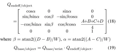

Fig.8.(a)Compliant wrist,(b)internal and external sensors arrangement,and(c)distance measurements from internal and external sensors.
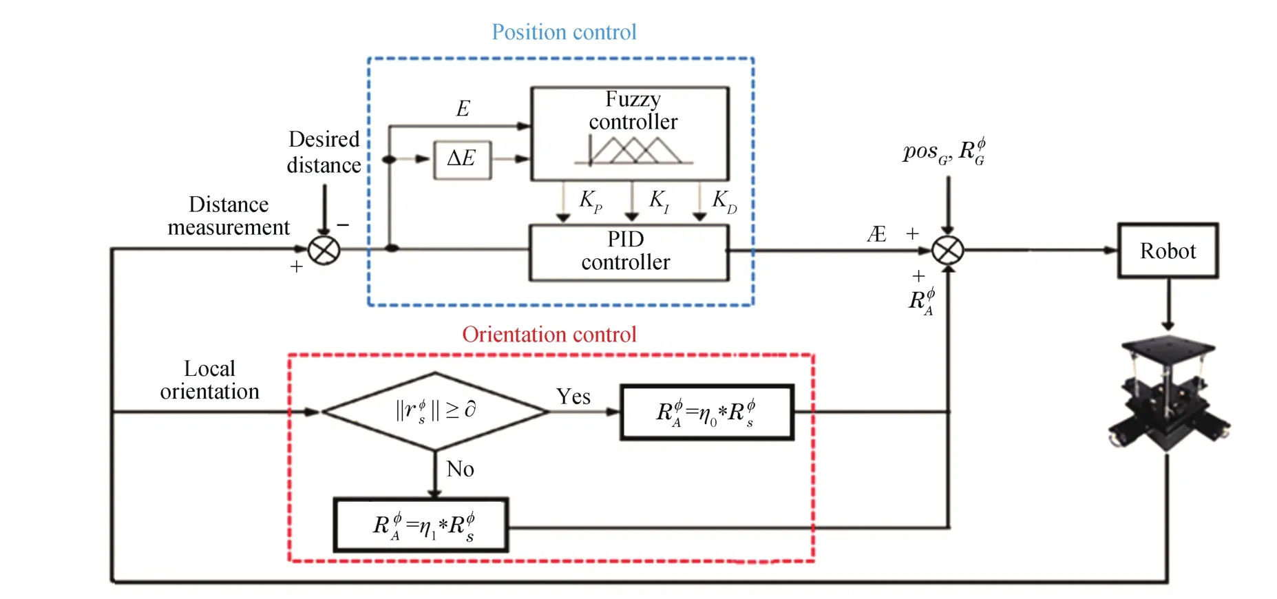
Fig.9.Block diagram of the real-time position and orientation controller.
A.Adaptive Position/Orientation Control
The surface following and tracking of the objects can be accomplished either with contact(for applications such as polishing,welding,or cleaning)or without contact(for applications like painting and inspection).In order to guide the robot under consideration of kinematic motion constraints,an adaptive on-line trajectory generation is proposed to generate continuous command variables and modify the position and orientation of the robot based on the online sensory information when the robot end-effector is in close proximity of(proximity control mode)or in contact with(contact control mode)an object.The robot position over the object’s surface is controlled using a fuzzy self-tuning PID controller and its orientation is corrected whenever there is an error between the surface orientation estimated via proximity/contact sensors and the end-effector’s orientation to make the system adaptive to the working environment(Fig.9).
1)Adaptive Position Control
The typical PID controller has been widely used in industry because of its simplicity and performance to reduce the error and enhance the system response.To design a PID controller it is required to select the PID gains KP,KI,and KDproperly(20).However,the PID controller with fixed parameters is inefficient to control systems with uncertain models and parameter variations.

where Ekis defined in(21).
Fuzzy control is ideal to deal with nonlinear systems where there is a wide range of operating conditions,an inexact model exists and accurate information is not required.It has a better performance in dealing with uncertainty and change in environment than a PID controller but PID has a faster response and it minimizes the error better than fuzzy control.Therefore,to take advantage of both controllers,a fuzzy self-tuning PID controller is designed to control the robot’s movement and to smoothly follow an object’s surface from a specific distance or alternatively while maintaining contact.
The fuzzy self-tuning PID controller’s output is a real-time adjustment value(Æ)of the position based on the error(E)between the current robot distance from the object(D)and the desired distance to the object d˘z(this value is zero when contact with the object is required).D is obtained by proximity sensors or by contact sensors on the compliant wrist when the robot is in close proximity of or in contact with the object respectively.The PID gains are tuned using the fuzzy system rather than the traditional approaches.The Æ is then sent to the robot controller to eliminate the error and make the system adaptive to the changes in the working environment.
The fuzzy controller input variables are the distance error(Ek)and change of error(∆Ek),and the outputs are the PID controller parameters.The standard triangular membership functions and Mamdani type inference are adopted for the fuzzification due to their less computation,which enhances speed of the system reaction

The error(Ek)in distance is represented by five linguistic terms:large negative(LN),small negative(SN),zero(Z),small positive(SP),and large positive(LP).Similarly,the fuzzy set of change of error(∆E)is expressed by negative big(NB),negative(N),zero(Z),positive(P),and positive big(PB),both defined over the interval from−50mm to 50mm.When the robot is in close proximity of the object,it can move backward,forward or not change depending on the robot distance to the surface.The output linguistic terms for each PID gain,andare(Fig.(10)):large forward(LF),forward(F),no change(NC),backward(B),large backward(LB)over the interval[−1,1].Tables I−III define the fuzzy rules for the,andgains.The center of gravity(COG)method is used to defuzzify the output variable(22).

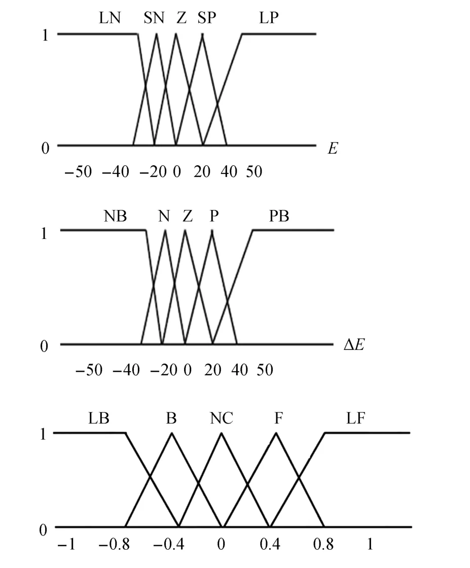
Fig.10.Fuzzy membership functions for:(a)error,(b)change of error,and(c)PID gains estimates ,and
In order to obtain feasible and optimum value for the PID parameters,the actual gains are computed using the range of each parameter determined experimentally(23)from the outputs of the fuzzy inference system.


where KP∈[0,1],KI∈[0.01,0.1],KD∈[0.003,0.01].
TABLE IFUZZYRULEBASE OFk

TABLE IFUZZYRULEBASE OFk
NB LB LB LB B NC N LB B B B NC Z LB B NC F LF P NC F F F LF PB NC F LF LF LF
TABLE IIFUZZYRULEBASE OF

TABLE IIFUZZYRULEBASE OF
NB LB LB LB F LF N LB B B NC NC Z B B NC F LF P NC B F F LF PB NC F LF LF LF
TABLE IIIFUZZYRULEBASE OF

TABLE IIIFUZZYRULEBASE OF
NB LF LF LB B LB N LF F F NC LB Z F F NC B LB P NC F B B LB PB NC B LB LB LB
2)Adaptive Orientation Control
When the robot is in close proximity of(or in contact with)the object,the orientation of the object surface is estimated by proximity/contact sensors in terms of the pitch()and yaw()with respect to the wrist plane.Let the rotation matrix of the surface generic orientation,be denoted withwith respect to the wrist plane,and the rotation of the end-effector obtained from the initial global trajectory,be described bythe desired rotation of the end-effector,to align the end-effector with the surface can be determined by(24)

In a surface following task,theis the orientation to be tracked by the robot.However,in order to obtain a smooth orientation,it is not directly sent to the controller.Instead,the orientation of the end-effector is updated using an adaptive orientation signal()at each moving step to compensate for the orientation error between the end-effector and the surface.The error decreases exponentially to eliminate the orientation error(adjustto zero)rapidly.

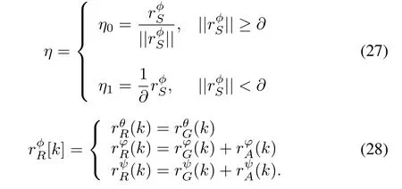
where η is a proportional gain to decrease the error and minimize the convergence time.A large gain value reduces the convergence time but may lead to tracking loss or task failure due to fast motion,while a small gain value increases the convergence time.Therefore,in order to increase the convergence time,reduce oscillation near equilibrium point and preserve the system stability,the gain value is varied according to the orientation error value(27).The gain value is small initially(η0)while the error is larger,and the error is reduced exponentially until it reaches a specific threshold(∂)near the equilibrium point(=0).Then,as the orientation error got smaller,the gain switches to a larger gain value(η0< η1)to eliminate the remaining orientation error as fast as possible[22].By using the adaptive orientation signal,the robot end-effector orientation angles are calculated by(28).
B.Updating the Occupancy Grid
The object of interest might not be acquired with sufficient accuracy by the Kinect sensor alone due to its limited depth resolution or not be segmented completely from the point cloud.In order to update the occupancy grid previously described,the compliant wrist provides closer and higher accuracy feedback about the object’s location.As shown in Fig.11,the compliant plate is able to cover four smaller cells(one largest cell),given the selected initial resolution of the occupancy grid.The external sensors,which are protruding on the four sides of the compliant plate,can provide real-time look-ahead information while the robot is moving.As the robot moves along the global trajectory to its new pose,the existing occupancy map is updated using the new measurements.For example when the robot is moving to the right,the sensor situated on the right side will allow an update of the state of the two cells located ahead on the right,especially when the next cell value is 0.5(unknown cell).If the sensor detects the object,the cell value changes to 1(occupied),else it will change to zero(empty).The robot keeps moving in the previous direction if the next cell is occupied,else it stops there and moves to the next pose along the global trajectory.
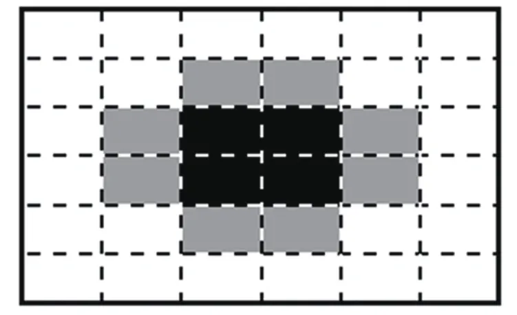
Fig.11.Cells coverage by the wrist embedded sensors.
V.SWITCHING CONTROL SCHEME
To achieve a seamless and efficient integration of vision and real-time sensory information and smoothly switch between different interaction modes,a mode switching scheme is also proposed as it provides the manipulator with the capability to operate independently in each of the 3 stages(free motion,proximity,and contact)or in transition in between stages to perform more complicated tasks as required by different applications.Since this work focuses on the task space control,a discrete-time switching system is proposed in order to switch smoothly between global trajectory following and sensor based motion control.The proposed switched-control system consists of continuously working subsystems and a discrete system that supervise the switching between the subsystems[23].The proposed switching control system is modeled as follows:

The value δ determines which function fδ(e)(Ek,Dk)controls the system behavior at each moving step(k)and fF,fP,fCcorrespond to free motion,proximity and contact control modes respectively.The switching signal δ(30)is determined based on the distance error(values are in mm).The error values shown in(30)are estimated experimentally based on the extensive compliant wrist sensor’s performance analysis detailed in[21].For a compliant wrist equipped with different IR sensors,or other robot-mounted distance measurement devices,re-calibration of(30)would be necessary,but the general framework would remain valid as such:

In the free motion phase,which refers to the robot movement in an unconstrained workspace,the 3D model of the object is used to plan a global trajectory(detailed in Section III)and guide the robot from an initial position towards the object where the robot pose is given by(31)

The proximity phase enables the robot to refine the reference(global)trajectory using the proximity sensing information to track the desired trajectory within a specific distance without contact or adjust the robot pose before contact happens(transition)to damp the system and align the robot with surface.It also enables the robot to update the cell of the occupancy grid while moving along the global trajectory.

where ÆPis position control signal generated by the selftuning fuzzy PID controller andis adaptive orientation control signal obtained using proximity sensors.
The contact with surface is triggered by the internal sensors where the contact plate is deflected under externally applied forces.The contact motion mode enables the robot to more precisely adapt to the changes and forces generated by the surfaces with which it comes into contact.When the contact is detected,the internal sensors provide the fuzzy inputs(error and change of error)instead of external sensors to make sure that the robot remains in contact with the object and prevent the robot from being pushed too much into the object.

where ÆPCandare adaptive position and orientation signals obtained from contact sensory information.
VI.EXPERIMENTAL RESULTS
To validate the feasibility and assess the accuracy of the proposed method,experiments are carried out with a 7-DOF CRS F3 manipulator which consists of a 6-DOF robot arm mounted on a linear track.The algorithms used for this work were developed in C++and run on a computer with an Intel core i7 CPU and Windows 7.
A.Object Segmentation
Table IV shows the efficiency of the proposed segmentation algorithm in extracting the object of interest from the scene shown in Fig.3 where there are four objects of different shapes and colors.The original point cloud provided by the Kinect sensor after applying the depth filter includes 41204 points from which over 99%of those corresponding to the objects of interest have been successfully recovered from the point cloud.

TABLE IVOBJECT SEGMENTATION RESULTS
B.Contact Interaction
In this experiment,it is desired to closely follow the surface of a real automotive door panel(Fig.12)while maintaining contact and accommodating its curvature.As shown in Fig.12(a),the Kinect sensor is located facing the door panel and the robot moves on a two-meter linear track to fully reach the surface.The Kinect collects raw 3D information on the environment.The RGB image captured by the Kinect(Fig.12(b))is presented to the operator.The operator selects the object of interest and its point cloud is automatically extracted from the scene,except for the window area since glass is not imaged well with Kinect sensor technology and also the window area is beyond the robot workspace.A global trajectory is then generated using the proposed coverage path planning method(Section III-B)to completely explore and scan the object of interest’s surface(Fig.13(a)).

Fig.12. (a)Automotive door panel set up with respect to the robot and the Kinect sensor,and(b)front view of real automotive door panel.
Fig.13(a)shows the global(of fline)trajectory generated using the proposed coverage path planning method,which consists of a set of 3D points(Fig.13(b)).Once the global trajectory is generated,the free motion mode is initially activated to guide the robot towards the start point.When the robot is in close proximity of the object,the proximity(external)sensors detect the object,the motion control mode is switched to the proximity mode,where the adaptive pose controllers adjust the robot position and orientation using the external sensors in preparation for a safe contact with the object.When the initial contact happens the control mode switches to contact mode,and the adaptive pose controllers generate the depth and orientation control signals to maintain contact with the object.The fuzzy inputs and the depth control signal are shown in Fig.13(c).The position control signal(Æ)is varying from−20mm to 25mm,which shows the smooth and stable motion of the robot over the object surface.The Æ signal changes according to the error(E)and change of error(∆E).When the robot moves horizontally the change of the Æ signal is small but when the robot moves vertically on the object surface,the E and∆E are changed more substantially(due to change of the door curvature).As a result,the Æ signal is larger to compensate the error as desired(Fig.13(c)).
The internal sensors detect the contact when the compliant wrist is deflected.In order to make sure that the robot is perfectly in contact with the object and detects the contact by the internal sensors,the desired distance to the object is set to d˘z=−3mm.Therefore,the average distance obtained from sensors in each moving step(k)should be around−3mm to eliminate the error(Ek=Dk−d).The average distance measurement of the internal sensors(Fig.13(d))from the object during the surface following process was about−3.42mm,which shows that the robot maintained contact during the interaction(Fig.(14)).The robot orientation error is compensated using the adaptive orientation signal().The robot moves to the next pose defined by the global trajectory and the same process as above repeats for each moving step until the robot has explored the entire surface.Fig.15 shows the system performance in refining the position and orientation of the robot during contact interaction.The depth adjustment over the object surface using the adaptive position controllers(depicted in red)is shown in Fig.15(a),and compared with the depth measurements estimated from the RGB-D data(depicted in blue).The orientation correction is represented in Fig.15(b),the global object surface orientation with respect to the robot base frame around the y-axis(in blue)and z-axis(in red)estimated as part of the off line path planning process are also updated locally using the online sensory information(in green and purple)from the compliant wrist.
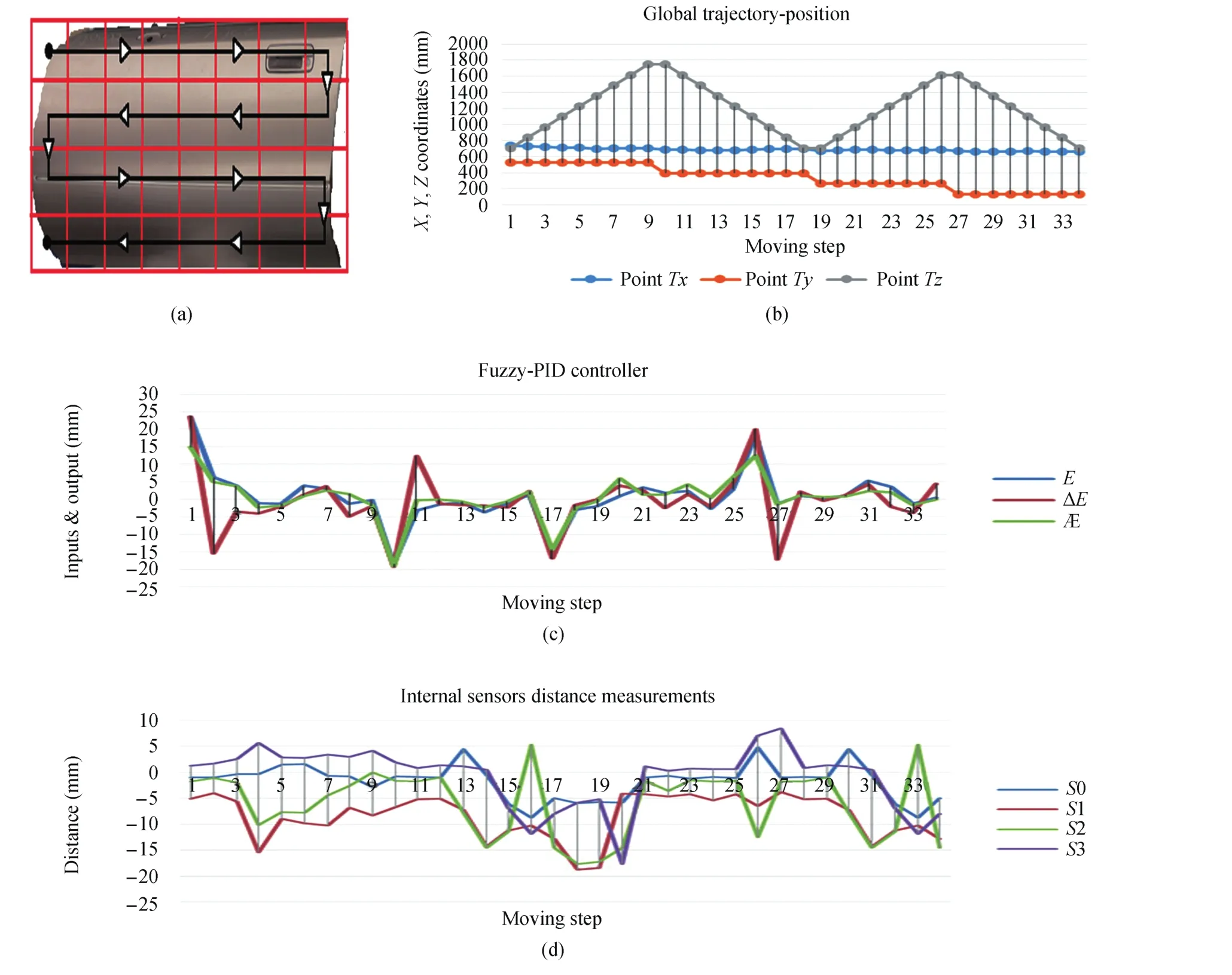
Fig.13.(a)Trajectory planning to ensure full coverage over the region of interest.(b)Global trajectory.(c)Fuzzy self-tuning PID controller performance.(d)Internal sensors dataset.
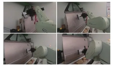
Fig.14.Robot performance at following the door panel’s curved surface.
C.Proximity Interaction
In this experiment,it is desired to scan and follow the object’s surface(Fig.12(b))at a fixed distance from it.Fig.16(a)shows the adaptive self-tuning fuzzy-PID performance in controlling the robot movement over the surface of the object while maintaining a desired distance(50mm)from the object but still accommodating its curvature(Figs.16(c)and(d)).In Fig.16(c),the blue curve represents the pre-planned trajectory which is locally refined(orange curve)using the sensory information provided by the external sensors.The global trajectory is also refined locally in orientation(Fig.16(d)).The average of the distance measurements(Fig.16(b))from the surface was 56.8mm,which verifies that the robot remains within the desired distance from the object during the surface following.
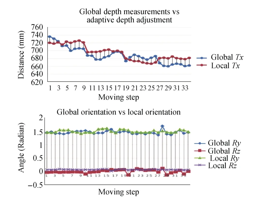
Fig.15.System performance in refining the robot pose in contact mode.
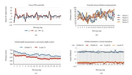
Fig.16.The system performance in refining the robot pose in proximity interaction.
VII.CONCLUSION
This work presented the design and implementation of a switching motion control system for automated and efficient proximity/contact interaction and surface following of objects of arbitrary shape.The proposed control architecture enables the robot to detect and follow the surface of an object of interest,with or without contact,using the information provided by a Kinect sensor and augmented locally using a specially designed instrumented compliant wrist.A tri-modal discrete switching control scheme is proposed to supervise the robot motion continuously and switch between different control modes and related controllers when it finds the robot within certain regions of the workspace relative to the object surface.The proposed method was implemented and validated through experimental results with a 7-DOF robotic manipulator.The experimental results demonstrated that the robot can successfully scan an entire region of an object of interest while closely following the curved surface of the object with or without contact.
The adaptive controllers and the switching control scheme can be improved in future work.This includes designing new adaptive controllers that are less sensitive and have faster but smoother response to changes in the environment,and using a hybrid switched control system to allow actual data fusion from multiple sensing sources which would result in smoother switching between the interaction modes.
ACKNOWLEDGMENTS
The authors wish to acknowledge the contribution of Mr.Pascal Laferrière to this research through the development of the instrumented compliant wrist device.
杂志排行
IEEE/CAA Journal of Automatica Sinica的其它文章
- Advances in Vision-Based Lane Detection:Algorithms,Integration,Assessment,and Perspectives on ACP-Based Parallel Vision
- Deep Scalogram Representations for Acoustic Scene Classification
- Adaptive Proportional-Derivative Sliding Mode Control Law With Improved Transient Performance for Underactuated Overhead Crane Systems
- On“Over-sized"High-Gain Practical Observers for Nonlienear Systems
- H∞Tracking Control for Switched LPV Systems With an Application to Aero-Engines
- Neural-Network-Based Terminal Sliding Mode Control for Frequency Stabilization of Renewable Power Systems
