Numerical investigation on convective heat transfer over two heated wall-mounted cubes in tandem and staggered arrangement
2018-07-27MouszdehShhmrdnTvngrKhHosseinzdehGnji
S.M. Mouszdeh, M.M. Shhmrdn, T. Tvngr, Kh. Hosseinzdeh, D.D. Gnji,*
a Department of Mechanical Engineering, Shahrood University of Technology, Shahrood, Iran
b Department of Mechanical Engineering, Babol Noushirvani University of Technology, Babol, Iran
Keywords:
ABSTRACT In this study, laminar convective heat transfer over two heated wall-mounted cubes is investigated.Two cubes, which are under constant heat flux, are placed in different tandem and staggered arrangements on a base plate. This problem is studied for different streamwise and spanwise distances between two cubes in different Renolds number (Re), by using finite-volume method.Effects of these parameters are considered on flow and heat transfer characteristics. The results show that the temperature distribution is strongly dependent on flow structure and varies with any change of flow pattern in different arrangements of cubes. In addition, it is observed that the drag coefficient, which is influenced more by pressure forces, in staggered arrangement, is greater than tandem arrangement. Results show that by increasing the spanwise distance the amount of mean Nusselt number (Nu) of Cube 2 becomes the same as Cube 1.
Convective heat transfer over wall-mounted cubes is one of applied issues in different fields of engineering. The main applications of this issue are electronic components cooling, flow in heat exchangers, and computation of heat losses at exterior building walls by atmospheric airflow, especially at power plant buildings. Hence, researchers considered study of flow and heat transfer in this geometry as an appropriate model of previously mentioned real examples. There are various experimental and numerical studies in this case. Most of these studies has been surveyed the flow and heat transfer around a single cubic obstacle [1-4]. The main and particular characteristic of flow in this typical geometry is formation of three-dimensional vortices around the cube. The obstacle in the route of the flow creates an adverse pressure gradient, which cause flow separation in upstream of the obstacle. This separated flow appears vortices that wrap around the obstacle and form a horseshoe vortex region.The flow which is conducted over the top surface of the cube, rebounds to the base plate, and creates hairpin vortices in the downstream wake region. Moreover, there are some small vortices in the vicinity of two lateral walls of the cube.
In this geometry, thermal boundary layer is strongly related to local flow structure. Morrise and Garrimella [1] investigated experimentally and numerically the temperature distribution around a cubic obstacle in fully developed water channel flow for 500 ≤ Re ≤ 1500 (laminar) and 10000 ≤ Re ≤ 25000 (turbulence), Re is Reynolds number. They observed an increasing wake temperature by increasing Re in laminar flow and sub-sequently decreasing buoyancy effects. However, in turbulence conditions any influence on the flow structure and wake temperature was not studied.
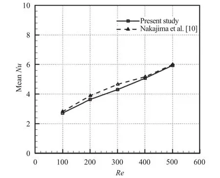
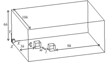
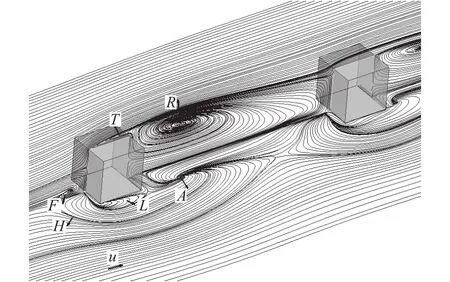
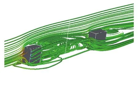
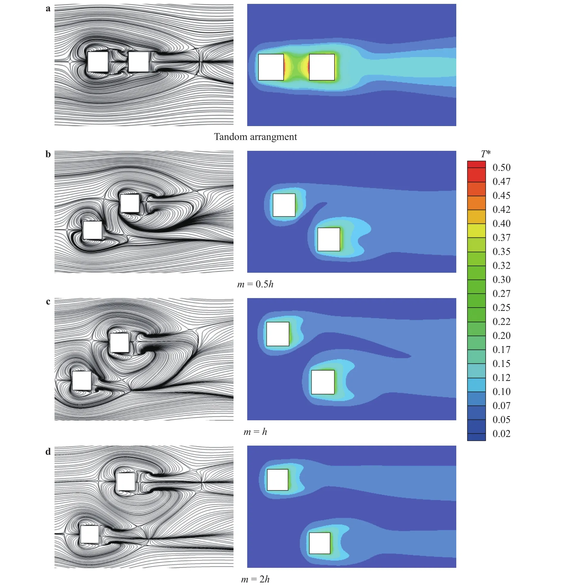
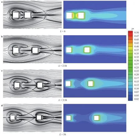
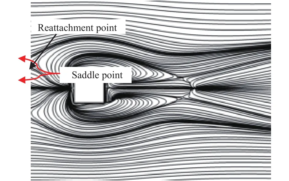
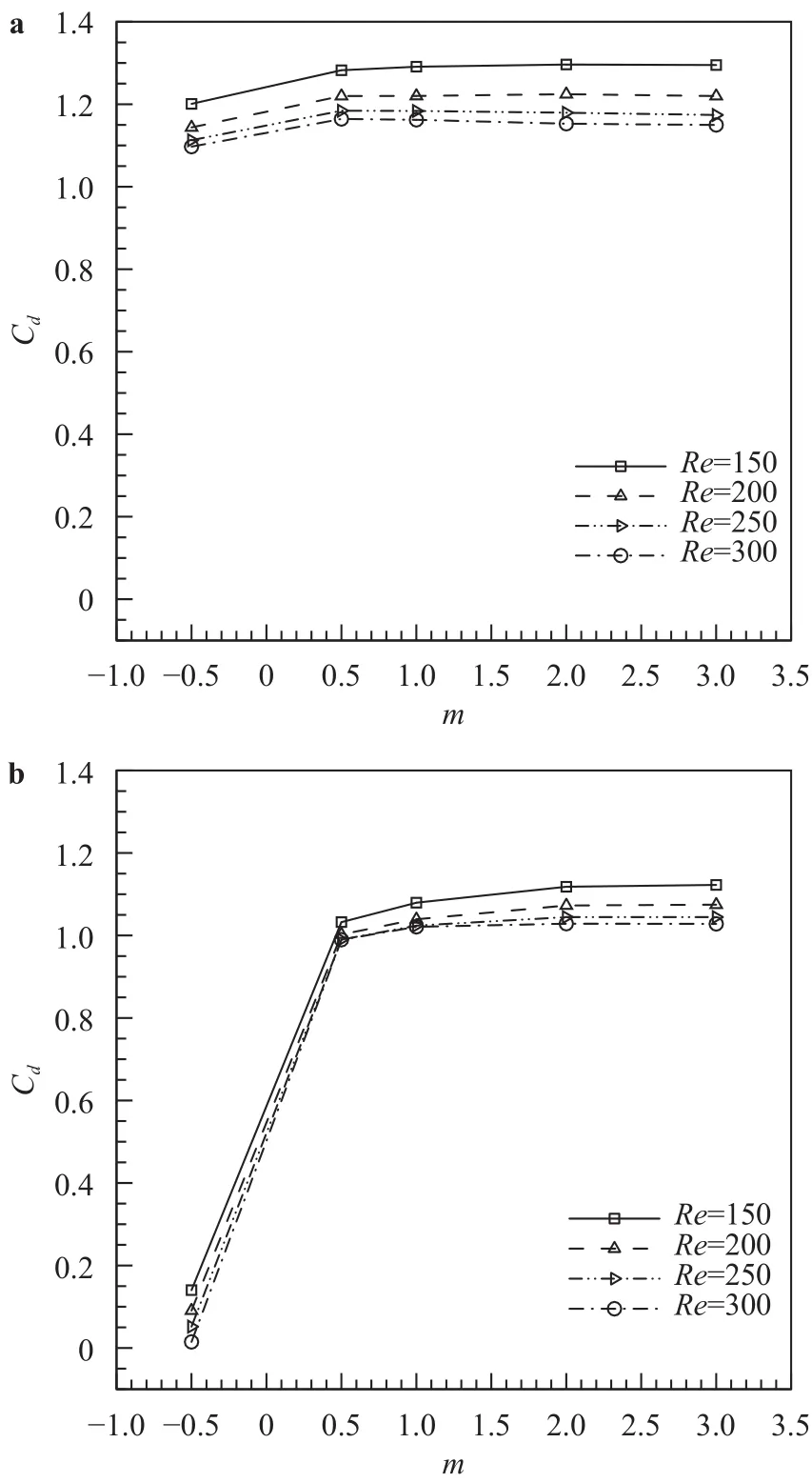
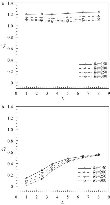
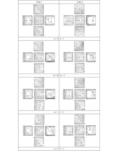
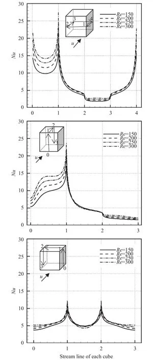
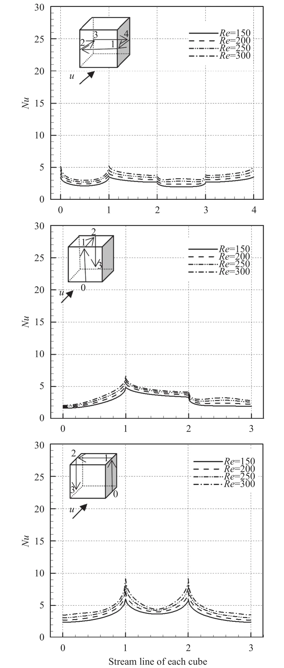
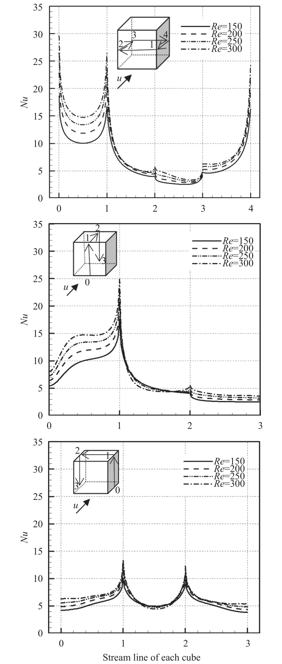
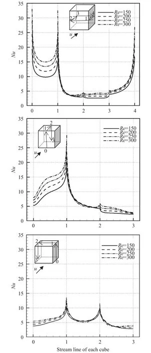
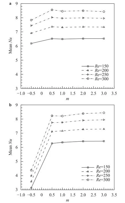
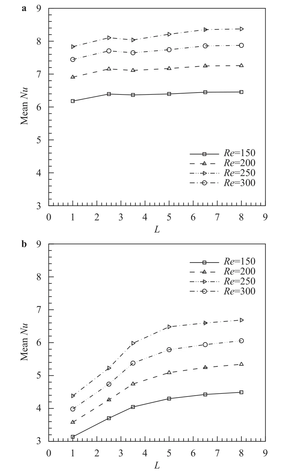
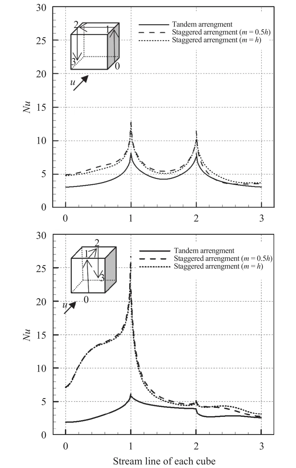
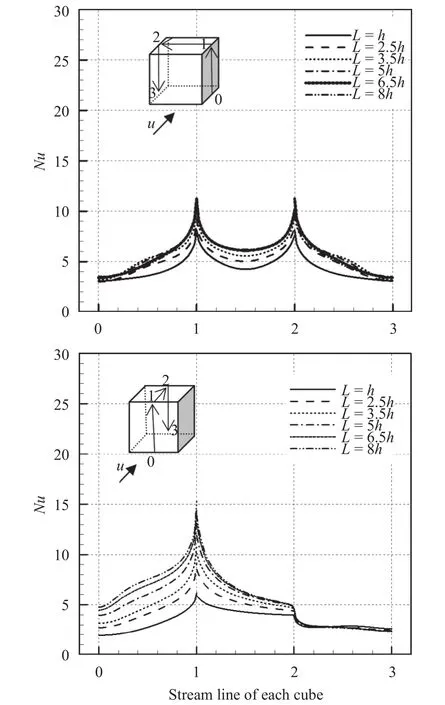
A numerical study of 2D forced convective flow around a warm square was performed by Yang and Vafaei [2]. In this study, the square was under constant heat flux and placed on a channel wall in a flow with Re in the range of 200–2000. The effects of different variables such as square walls height and width and Re on flow field and heat transfer were discussed. The results show that the shape and size of obstacles can make an impressive influence on the flow and heat transfer. Moreover average Nusselt number (Nu) increases by raising Re. Nakamara et al. [3] detailed in an experimental investigation the flow and heat transfer characteristics around a 3D cube on a plate for 4.2×10³ Fig. 1. Comparation of pressure distribution Cp in the present study and the study reported by Eslami et al. [16] on y = 0.5h line, at x =0.5h plane downstream of Cube 1 in L = h case of tandem arrangement and Re = 200. Fig. 2. Comparation of the diagram of mean Nu at different Re on Cube 2 in L = 4.5h case of tandem arrangement in the present study and the study reported by Nakajima et al. [10] Fig. 3. Geometry of cube arrangement. Fig. 4. Flow field and vortices in tandem arrangement. Fig. 5. Flow field and vortices in tandem arrangement in 3D state. Fig. 6. Streamlines and temperature contours on base plate in L = h, Re = 250 and different spanwise distances. Fig. 7. Streamlines on base plate in L = h, Re = 250 and different streamwise distances. Recently, numerous papers has demonstrated the effect of nanoparticle on heat transfer rate [17-32]. Akbari–Ganji's method (AGM) is implemented to simulate nanofluid flow between two pipes in the existence of magnetic field [17]. The effect of magnetic field on water based nanofluid considering various types of nanoparticles investeigated by Sheikholeslami and Ganji [20]. The comprehensive review has been reported on the influence of nanofluids on heat transfer characteristics [26].Some studies are about flow over several obstacles in other shapes, different arrangements [33-36] and also heat transfer of special fluids such as nanofluids over obstacles [37-45]. Since there is no perfect study about the effects of distances between two cubes on heat transfer characteristics for 3D laminar fluid flow in both tandem and staggered arrangement so far. Therefore, it is studied in this paper. For validation of results, pressure distribution on y = 0.5h line, at x = 0.5h plane downstream of Cube 1 in L = h case of tandem arrangement and Re = 200 is compared with investigation of Eslami et al. [16] as shown in Fig.1. Moreover, the diagram of mean Nu at different Re on Cube 2 in L = 4.5h case of tandem arrangement, is compared with the same diagram in the study reported by Nakajima et al. [10] as shown in Fig. 2. A great agreement has been observed between the present study and two aforementioned ones. By mentioned above, there is no perfect study about the effects of distances between two cubes on heat transfer characteristics for 3D laminar fluid flow in both tandem and staggered arrangement so far, so it is studied in this paper. In this study finite volume method is used for solving continuity, momentum and energy equations on account of investigating convective heat transfer around tow wall-mounted cubes under constant heat flux, which are placed in tandem and staggered arrangements on adiabatic base plate. In all cases, Re (based on height of cube)are from 150 to 300 and Pr is 0.7. And finally, the effects of different variables like streamwise and spanwise distances and Re on streamlines, drag coefficient, average and local Nu at surfaces of obstacles and temperature distribution on them and base plate are described. Fig. 8. Saddle points and reattachment point. Fig. 9. Total drag coefficient at different spanwise distances in staggered arrangement. a Cube 1, b Cube 2. Fig. 10. Total drag coefficient at different streamwise distances in tandem arrangement. a Cube 1, b Cube 2. The geometry of this investigation includes two cubes with same dimensions h, which are placed on a base plate. The dimensions of the base plate as shown in Fig. 3 are 10h in z-direction and (13h + l) in x-direction, in which “l” stands for the distance between two cubes. The distance between the leading edge of the Cube 1 to the beginning of the base plate is 3h and the distance between the back edge of Cube 2 to its ending to is 8h. The dimension of computational domain in y direction is 8h.The distance between two cubes in z-direction is designated by m. The distance between two cubes and the symmetrical lateral planes is equal in all arrangements. In this study, the boundary conditions for velocity and temperature are uniform in the entrance plane of the flow and have zero gradients in the outlet plane. The lateral planes are supposed symmetric and free stream condition is applied on the top plane. All of the walls have no slip boundary conditions. All surfaces of the two cubes are under constant heat flux and base plate is supposed adiabatic. Fig. 11. Dimensionless temperature distribution on base plate at different spanwise distances. Governing equations in this study are dimensionless form of continuity, momentum and energy equations for 3D steady state laminar incompressible flow as follows: Fig. 12. Local Nu distribution over symmetryline of Cube 1 surfaces in L = h case of tandem arrangment. Fig. 13. Local Nu distribution over symmetryline of Cube 2 surfaces in L = h case of tandem arrangment. Fig. 14. Local Nu distribution over symmetryline of Cube 1 surfaces in m = 0, L = h case of tandem arrangment. That the following dimensionless parameters are used in upon equations: Fig. 15. Local Nu distribution over symmetryline of Cube 2 surfaces in m = 0.5h, L = h case of tandem arrangment. In above relations Tinand Uinare the amounts of temperature and velocity in inlet plate, and q″ is the amount of constant heat flux on the two cubes’ surfaces. All equations are solved based on Re in the range of 150–300 and Pr = 0.7. The Richardson number has been less than 0.017 for the least Re, therefore the effects of natural convection can be neglected in all equations. In this study, it is used a developed Open Field Operation and Manipulation (OpenFOAM) code for solving governing equations that applies finite volume method. The OpenFOAM CFD Toolbox is a free, open source CFD software package. It has a large user base across most areas of engineering and science,from both commercial and academic organizations. Open-FOAM has an extensive range of features to solve anything from complex fluid flows involving chemical reactions, turbulence and heat transfer, to solid dynamics and electromagnetics. The core technology of OpenFOAM is a flexible set of efficient C++modules. These are used to build a wealth of solvers, to simulate specific problems in engineering mechanics; utilities, to perform pre and post-processing tasks ranging from simple data manipulations to visualization and mesh processing; libraries, to create toolboxes that are accessible to the solvers/utilities, such as libraries of physical models. OpenFOAM is supplied with numerous pre-configured solvers, utilities and libraries and so can be used like any typical simulation package. However, it is open,not only in terms of source code, but also in its structure and hierarchical design, so that its solvers, utilities and libraries are fully extensible. OpenFOAM uses finite volume numeric to solve systems of partial differential equations ascribed on any 3D unstructured mesh of polyhedral cells. The fluid flow solvers are developed within a robust, implicit, pressure-velocity, iterative solution framework, although alternative techniques are applied to other continuum mechanics solvers. Domain decomposition parallelism is fundamental to the design of OpenFOAM and integrated at a low level so that solvers can generally be developed without the need for any "parallel-specific" coding.More details are presented in Refs. [47-48]. In this code, it is used SIMPLE algorithm for coupling pressure and velocity. In momentum and energy equations, diffusion term is discretized by Gauss linear corrected method with second order accuracy, and convection term is discretized by Gauss upwind method with first order accuracy. The Gauss keyword specifies the standard finite volume discretization of Gaussian integration of values from cell center to face center. Fig. 16. Mean Nu at different spanwise distances in L = h case for a Cube 1, b Cube 2. Fig. 17. Mean Nu at different streamwise distances in tandemn arrangment for a Cube 1, b Cube 2. Since near the two heated cubes’ walls temperature and velocity gradients are higher than other points of computational domain, to achieve more accuracy in computation the grids are designated smaller in these regions. These grids are growing gradually while distancing from the edgewise. The dimensions of the smallest grid are 0.00417h in x-, y-, and z-directions. Similar to other investigations in this typical geometry, the most important thing observed in flow field around two cubes is formation of 3D vortices due to presence of cubes in the route of the flow. These vortices consist of horseshoe vortexes caused by flow separation in upstream of each cube (H), vortices in the vicinity of side surfaces (L), top surface of cubes (T), hairpin vortices in downstream wake region of cubes (A), small vortices in upstream of cubes (F), and vortical region in backside of cubes(R). All of these vortices for Cube 1 in tandem arrangement are shown in Fig. 4. Three dimensional of flow field and all vortices around cubes can be seen in Fig. 5. Fig. 18. Local Nu distribution over symmetryline of two cubes surfaces in L = h case, Re = 250 and different spanwases. Shape and size of these vortices are strongly influenced by arrangements of the two cubes, their streamwise and spanwise distances. The streamlines, and temperature contours on base plate are shown in Figs. 6 and 7. By increasing streamwise distance (l) in tandem arrangement and spanwise distance (m) in staggered one, the overlapping of vortex regions of each cube to the other one decreases. So flow structure around each cube gradually approaches to the flow structure around a single cube(Fig. 6.(d), (e) and Fig. 7.(c)-(e)). Such a flow structure in some similar arrangements on higher surfaces parallel to the base plate (but not y = 0) was observed by Eslami et al. [16]. Due to small distances in tandem arrangement, the high separation occurs in upstream flow of Cube 2 momentum flow passed from Cube 1 comes down right on the top surface of Cube 2. Thus, the Cube 1 horseshoe vortex region is wrapped around this cube too. With increasing the distance, independent horseshoe vortexes are appeared around Cube 2 gradually. This is the starting indication of the flow separation before arriving to the Cube 2. Such result matches acceptably with the ones achieved by Eslami et al. [16] and Meinders and Hanjalic [13]. In the downstream of the cubes due to the collision of rotational vortices to the base plate, in some points returning flow is observed, which are called reattachment points (Fig. 8). Some portions of the rotational vortices that pass these points are returned toward upstream while the others continue their path to the downstream. The returned flow portion that cross the reattachment points creates a line of attachment that is a symmetry line for the downstream wake region of each cube in symmetric flow states. The other important point that observed in such flow structures is named saddle point (Fig. 8). In this point that is detected as a concavity in the base plate flow pattern, convergent streamlines deflect and become divergent. Fig. 19. Local Nu distribution over symmetryline of Cube 2 surfaces in tandem arrengment and different spanwases at Re = 250. In staggered arrangement and small spanwise distances (m =0.5h and m = h) horseshoe vortexes are very asymmetric. In m =0.5h, there is no reattachment point. With increasing spanwise distance to m = h reattachment point of the Cube 1 appears but it is not symmetric yet. In m = 2h, flow become symmetric and the reattachment point of the Cube 2 is also appeared. Various vortices around obstacles cause the ratio of pressure drag on total drag to be much more than the ratio of friction drag. Since there are further and larger vortices in staggered arrangement in comparison with tandem one, total drag coefficient in tandem arrangement is less than staggered one (Figs. 9 and 10). As mentioned above in tandem arrangement, flow around the Cube 2 converts from shear layer. According to wall-constant heat flux and energy transfer between particles attached to the cubes and flow in small streamwise distances to horseshoe vortex structure flow in larger ones. Therefore total drag coefficient of Cube 2 in this type of arrangement increases with raising streamwise distance. As it is shown by increasing Re and decreasing frication drag coefficient subsequently, total drag coefficient decreases. Due to temperature gradient in the fluid, the thermal boundary layer is created.Whereas for incompressible fluid, the energy equation is independent from the continuity and momentum equations, for obtaining T (x, y, z) from energy equation V (x, y, z) should be known. Therefore, the temperature field depends on the velocity field strongly. This relevance can be seen clearly in the temperature contours on the base plate for both tandem and staggered arrangements (Figs. 6 and 7). In the arrangements with overlapping of vortex regions of the two cubes, overlapping of thermal boundary layers is also observed. Vortices hold on the therm of heated walls and cause increasing fluid temperature with decreasing heat transfer in such region simultaneously. Thus, similar temperature distribution on cubes' surfaces that their adjacent flow has the same vortices structure is observed. As shown in Fig. 11, a similar temperature distribution is observed on the leading surface of each cube,which a flow separation occurred beforehand. Also there is a similar temperature distribution on the out-standing lateral and the top surfaces of both of the cubes. Due to symmetrical vortices adjacent to those surfaces of the cubes, a symmetric temperature distribution can be seen. Obviously, by the disappearance of this symmetry in vortex region the temperature distribution becomes asymmetric too. As observed in this figure a symmetric temperature distribution lines at the rear surface of the cubes, in tandem arrangement converts to asymmetric one in staggered arrangement. On the side surfaces the concentration of high temperature is at the center of lateral vortices. Other important thing which can be seen in temperature distribution contours is that thermal boundary layer thickens by heated fluid during movement toward downstream. This proposition causes heat transfer reduction. By this reason as seen in Figs. 6 and 7,thermal boundary layer thickness around Cube 2 is rather than it around Cube 1. Heat transfer reduction for adjacent flow of rear surface of each cubes in comparison of their leading surface, except for the L = h case of tandem arrangement due to increasing downstream fluid temperature is shown in Figs. 12-17. In L = h case of tandem, heat is held in the cavity space between two cubes and so fluid temperature in vicinity of rear surface of Cube 1 and leading surface of Cube 2 increases. Maximum heat transfer or Nu is observed for leading surface of Cube 1 because there is maximum temperature difference between this hot surface and upstream cold fluid. There is minimum heat transfer at rear surface of Cube 2. It is due to a lowtemperature difference between fluid and the rear surface. On the top and lateral surfaces heat transfer decreases bearing downstream too. As it was observed from Fig. 17 by increasing the distances between two cubes in tandem arrangement, downstream fluid temperature decreases and mean Nu increases gradually. Moreover, the effect of distances in local Nu of Cube 2 is shown in Figs. 18 and 19. It is detected from local and average Nu diagram, with increasing Re, momentum and energy transfer and then Nu increase. All obtained results are in good agreement with Nakajima et al. [10] experimental investigation for turbulence flow. In this study, laminar convective heat transfer over two heated wall-mounted cubes is investigated. Two cubes, which are under constant heat flux, are placed in different tandem and staggered arrangements on a base plate. The results showed that (1) Complex phenomenas such as flow seperation, horseshoe vortexes, flow reattachment, hairpin vortices have been observed which will influence in flow and heat transfer characteristics. Since there are further and larger vortices in staggered arrangement in comparison with tandem one, total drag coefficient in tandem arrangement is less than staggered one. (2) The temperature field depends on the velocity field strongly and changes by changing flow structures in different arrangements of the two cubes. Vortices trap the therm of heated walls and cause increasing fluid temperature with decreasing heat transfer in such region simultaneously. (3) Similar temperature distribution on cubes' surfaces that their adjacent flow has the same vortices structure is observed.By increasing downstream fluid temperature heat transfer around the Cube 2 is less than the Cube 1. By increasing Re, momentum and energy transfer and then Nu increase.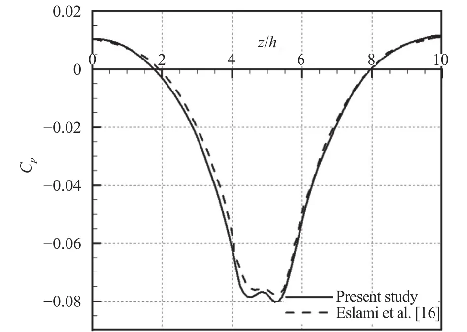




杂志排行
Theoretical & Applied Mechanics Letters的其它文章
- Rational subgrid-scale modelling: a short survey
- Rowing jellyfish contract to maintain neutral buoyancy
- Effects of tide-surge interaction and wave set-up/set-down on surge: case studies of tropical cyclones landing China's Zhe-Min coast
- Wave reflection in semiconductor nanostructures
- Achieving thermal magnification by using effective thermal conductivity
- Nonlinear thermo-structural behavior of sandwich panels with truss cores under through-thickness gradient temperature field
