Nonlinear robust control of a quadrotor helicopter with finite time convergence
2018-06-04GuozhouZHENGBinXIAN
Guozhou ZHENG,Bin XIAN
School of Electrical and Information Engineering,Tianjin University,Tianjin 300072,China
1 Introduction
The navigation and control of unmanned aerial vehicles(UAVs),also known as drones,has become an important research area over the past decades[1,2].As a micro helicopter,the quadrotor UAV attracts great attention from military and civil applications due to its special advantages such as simple structure,vertical taking off and landing(VTOL),and rapid maneuvering.It has been widely used in a variety of situations including surveillance,fire flighting,environmental monitoring,etc.[3–5].Comparing to the flapping-wing aircraft and other configurations,quadrotor UAV is simple in mechanism,and its four identical rotors are the only moving parts onboard.The simplicity in mechanism is a trade-off with the dependency of sophisticated flight controller[6,7].However,the quadrotor is a highly nonlinear and time-varying system,and it has an unstable open-loop dynamics[8].Additionally,due to its small size and weight,the quadrotor is very sensitive to external aerodynamic disturbances such as wind gusts and ground effect.Therefore,the design of highperformance nonlinear control mechanisms for quadrotors in the presence of structural uncertainties and unknown external disturbances is still a challenging task.
To guarantee a safe and steady flight against external disturbances,various control methods have been developed for quadrotors in recent years.In[9],the authors developed an H∞based attitude controller for the quadrotor’s attitude subsystem.In[10],the timevarying disturbance was treated as a new unknown state and estimated by an extended observer.Then,a sliding mode based feedback controller was employed for the attitude stabilization,and numerical simulation results were included.An integral sliding mode based robust controller is proposed for the control of a quadrotor in[11],though the proof of the stability and numerical simulation results were presented,the control gains were not very easy to be tuned.In[12],the authors developed a nonlinear robust attitude control algorithm for a quadrotor with uncertain dynamics by combing a PD controller with a robust compensator,and ultimately bounded attitude tracking result was proven.Based on these works in[12],the authors former extend the control strategy in[13],where both position and attitude controllers were developed,the tracking error were proven to be kept within a known neighborhood of the origin ultimately.A nonlinear robust adaptive was developed in[14]for a quadrotor with linear parameterized(LP)uncertain-ties and bounded disturbances,semiglobally asymptotic tracking of a time-varying position trajectory and yaw angle trajectory was proved via a Lyapunov-based stability analysis.In[15],authors designed an attitude controller by using exponential coordinatesto avoid singuarlities,and trajectory linearization method was employed to facilitate the control design procedure.
Though a lot of controller have been developed for the control of quadrotors,most of them can not guarantee the convergence time for the quadrotor’s outputs.The super twisting algorithm,which is a second order continuous sliding mode control technique that ensures robustness in the presence of the smooth matched disturbance with bounded gradient,is implemented for attitude control of a quadrotor in[16]with known knowledge of the boundary of the disturbance gradient.
Motivated by the control methodology presented in[17],we develop a new nonlinear robust controller for the quadrotor with the attitude angles and altitude position selected as the system’s outputs.An adaptive super-twisting algorithm is combined with backstepping method to formulate the controller.The proposed controller does not require the exact knowledge of the boundary of the disturbance or its gradient.By using the super-twisting algorithm,the control inputs to the quadrotor suffers little from the chattering phenomenon,and the adaptive laws ensure that the control gains will be easy to be tuned.Lyapunov based stability analysis is employed to show that the closed-loop operation is stable,and the tracking errors converges to an eighbor hood of the origin with finite convergence time.Moreover,to increase the measurement accuracy for the altitude channel where low-cost on board sensor were very sensitiveto noise,anonlinear complementary filter isdeveloped to fuse the raw data from the onboard accelerometer and barometer.The stability and convergence of the filter is also proven via Lyapunov based analysis.Realtime experimental results are implemented on a selfmade quadrotor helicopter testbed,the results show that the proposed control strategy has achieved good control performance for the quadrotor.
Therefore,the contribution of the proposed design includes that:1)a nonlinear complementary filter is designed to provide accurate estimation for the quadrotor helicopter’saltitudebased on raw datafrom theonboard low cost sensors;2)the super-twisting based nonlinear controller can achieve finite time convergence of the attitude tracking error under the effects of unknown external disturbances without exact knowledge of the disturbances’upper bound;and 3)real-time flight experimental results have testified the good performance of the proposed methodology.
This paper is organized as follows:The dynamics model of the quadrotor helicopter and control objective are described in Section 2.Section 3 presents the design of the nonlinear complementary filter design for the altitude channel.Section 4 provides details of the control development and stability analysis.Real-timeexperimental results are included in Section 5 to validate the controller’s performance.Finally,some conclusion remarks are included in Section 6.
2 Dynamic model of the quadrotor
The quadrotor UAV can be considered as a rigid body with 6 degree-of-freedom(DOF):three translational motions and three rotational motions As illustrated in Fig.1,two frames are utilized to represent the motion of the quadrotor.Let I={xI,yI,zI}denote the right-hand inertia reference frame,and B={xB,yB,zB}denote the right-hand body-fixed reference frame.The altitude of the UAV with respect to I is denoted by z(t)∈R,and Euler angle vector of the UAV with respect to I is denoted by η(t)=[φ(t) θ(t) ψ(t)]T∈ R3where φ(t),θ(t)and ψ(t)are the quadrotor’s roll angle,pitch angle,and yaw angle,respectively.The rotation matrix from B to I is presented as follows[18]:
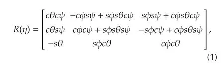
where c(·)is the abbreviation for cos(·),and s(·)is the abbreviation for sin(·).In Fig.1,fifor i=1,...,4,represents the independent thrust force generated by the four rotors of the quadrotor.
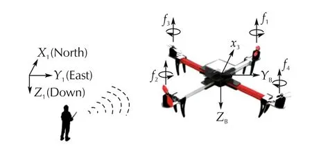
Fig.1 Schematic of a quadrotor UAV.
The attitude dynamics of the quadrotor considered in this paper can be modeled via the following differential equations[18]:

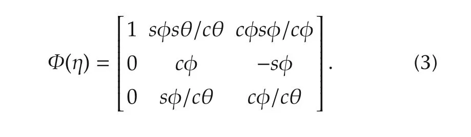
where Ω(t)=[p(t)q(t)r(t)]Trepresents the angular velocity vector of the quadrotor with respect to B,τ(t)=[τφ(t) τθ(t) τψ(t)]T∈ R3denotes the control torque input vector,d(t)=[dφ(t)dθ(t)dψ(t)]T∈ R3is the unknown external disturbance moment vector.In(2),J=diag{[JφJθJψ]}∈ R3×3denotes the inertia matrix with Jφ,Jθ,and Jψbeing some positive constants,the matrix Φ(η)∈ R3×3represents the rotational velocity transfer matrix from B to I which has the following form[4]
The following assumption will be employed in the subsequent control development.
Assumption 1The disturbance term d and its time derivative˙d are bounded such thatwhere δ1and δ2are some unknown positive constants.
The dynamic model for the altitude channel of the quadrotor is shown as follows[18]:

where m∈R represents the mass of the quadrotor,ut∈R is the total thrust in the z-direction,g is the acceleration of gravity,and dt(t)∈R denotes the unknown external disturbance force in the z-direction.The following assumption will be utilized in the subsequent control development.
Assumption 2The disturbance item dtand its time derivativeare bounded such thatδz2where δz1and δz2are some unknown positive constants.
Assumption 3Therollangleφ(t)and the pitch angle θ(t)satisfy the following inequalities:
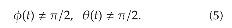
This assumption has also been employed in[13].
The relationship between the control inputs[τφτθτψut]Tand the rotor thrusts force[f1f2f3f]Tis given by
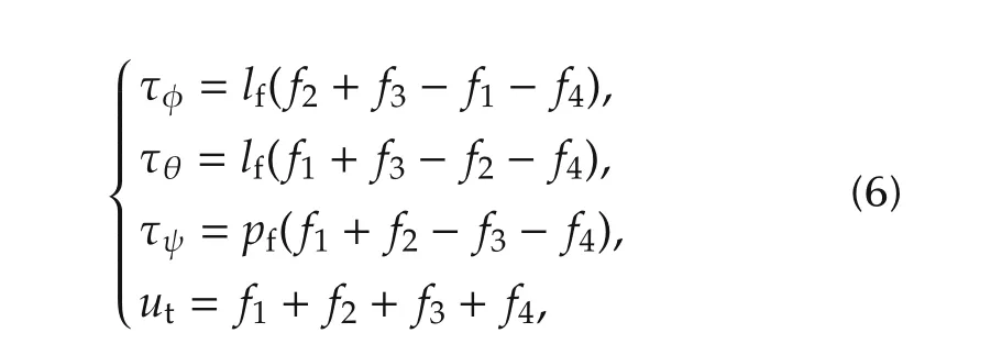
where lfis the distance from each rotor to the center of the quadrotor,and pfis the force-to-moment scaling factor.
The main control objective is to design control inputs(τ,ut)to drive the quadrotor’soutputs(η(t),z(t))to track some pre-defined reference trajectory(ηd(t),zd(t)).
3 Nonlinear complementary filter for the altitude measurement
In this paper,two low cost and light weight onboard sensors are employed to provide altitude measurements for the quadrotor,the first one is the barometer,and the other one is the accelerometer.The onboard barometer can provide a rough relative altitude measurement with an accuracy of about±0.5m which is not good enough for accurate hovering control of the quadrotor,and the onboard accelerometer returns an acceleration measurement in the altitude direction which is characterized with high noise levels and biases.A nonlinear complementary filter is introduced to deal with the misalignment of the accelerometer axes and factitious placement failure as well as some other nonlinearities,thus good altitude estimation can be obtained via the raw outputs from the barometer and the accelerometer.
To implement the nonlinear altitude fusion algorithm,an altitude measurement dynamics model with consideration of the proposed nonlinearities is introduced as follows:
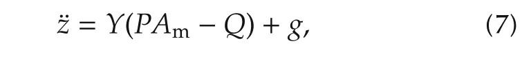
where z(t)is defined in(4)and denotes the real altitude value of the quadrotor,P ∈ R3×3denote a matrix relevant to the misalignment of the sensor axes and measuring sensitivity differences among each axis,3denotes the transpose of the third column of the rotation matrix R defined in(1),Q∈R3denote the bias vector,and Am∈R3denotes the outputs from the accelerometer.
Remark 1In an ideal circumstance where the accelerometer’s outputs reflect the real acceleration value of the quadrotor,P will equal to an identity matrix I3,and Q will be a zero vector.
Assumption 4The matrix P and Q in(7)are unknown constant terms such thatAnd the altitude channel is assumed to be measurable for low frequency such that zm(t)≈z(t)where zm(t)denotes a reconstructed altitude measurement[22].
Let the auxiliary estimation errors em(t),σm(t)∈ R be defined as follows:
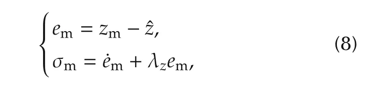
whereis the output of the following nonlinear complementary filter,and λzis a positive constant.The nonlinear complementary filter for the altitude channel is designed as follows:
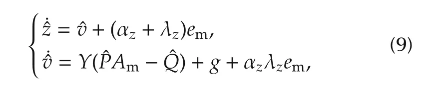
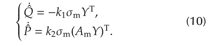
where αzis a positive constant,ˆv(t)denotes the estimation for the vertical speed.The adaptive laws ofand ˆQ(t)are designed as
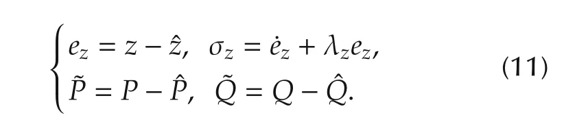
Let the auxiliary error signals ez(t)∈ R,σz∈ R,,andbe defined as follows:
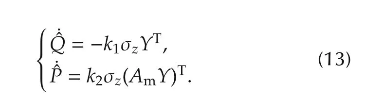
Taking Assumption 2 into account,(9)and(10)can be rewritten as
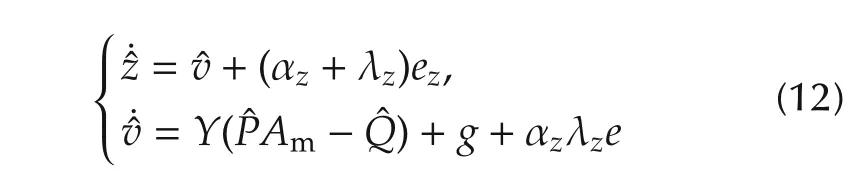
and
Theorem 1The proposed filter in(9)and(10)ensures an accurate estimation for the altitude and vertical speed such that
ProofAfter taking the time derivative of(12)and substituting(13)into the result,the following dynamics forcan be obtained
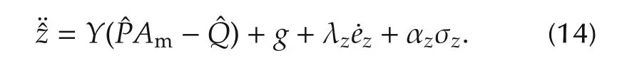
Let the Lyapunov function candidate Vez(t)∈R be defined as
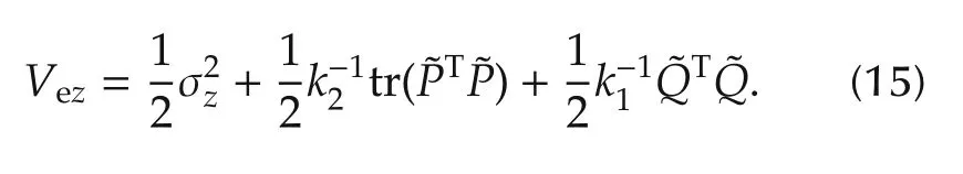
By taking the time derivative of Vez(t)and substituting(8),(11)and(14)into the result,it can be obtained that
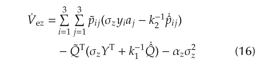
considering that P,Amand Y in(15)can be denoted by,and Am={aj}3×1.By substituting(13)into(16),it can be obtained that
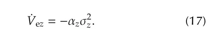
From(17)and(15),it is not difficult to show that σz(t)converges to zero asymptotically.Recalling thatwith λzbeing a positive constant,then it can be shown that.Thus,it can be shown thatvia(11).Finally,since ez(t)→ 0 as t→ 0,we know thatbased on the first entry of(12).□
4 Control development
This section presents the control design procedure for attitude angles and altitude position of the quadrotor under modeling uncertainties and unknown external disturbances.
4.1 Design of the attitude controller
A modified backstepping method is combined with the adaptive super-twisting algorithm to formulate the proposed control strategy.Before presenting the control laws,we introduce the following error signals:
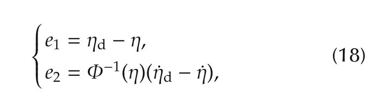
where ηd(t) ∈ R3denotes the desired attitude trajectory vector.The stabilization of e1can be obtained by introducing a virtual control input for e2as follows:
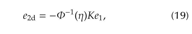
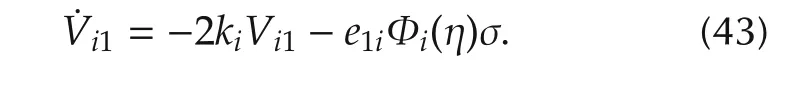
where K=diag{ki}∈ R3×3with ki> 0,i= φ,θ,ψrepresent a gain matrix.By defining σ =e2d−e2,the time derivative of(18)can be obtained as
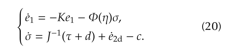
It is worth noting that if σ=0,then e1converges asymptotically to zero.Our control objective is to force σ to stay in a bounded domain,and,therefore,e1is also bounded in a domain.
The attitude controller is designed as follows:
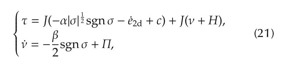
where α and β denote some diagonal positive-definite adaptive gain matrixes such that α =diag{αi}and β =diag{βi}for(i= φ,θ,ψ),sgn(·)denotes the standard signum function.The gains αiand βihave the following adaptive laws
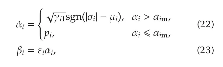
where εi, γi1, μiand piare some positive constants.The parameter αimrepresents an arbitrary small positive constant which is used as the switching threshold value.In(21),the auxiliary function vectors Π ∈ R3×1and H ∈ R3×1are defined as follows:
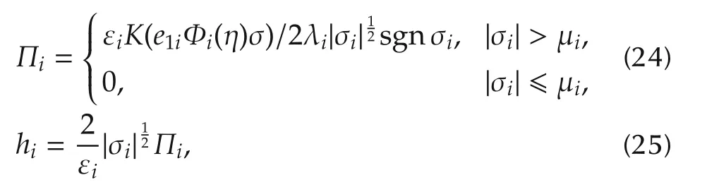
where the defined function K(x)=0 for x≥0 and K(x)=x for x<0,e1idenotes the i th element of e1and Φi(η)represents the i th row of Φ(η).
The main stability result of the adaptive attitude controller proposed in(21)is stated by the following theorem.
Theorem 2The proposed attitude controller in(21)can drive e1(t)and its time derivativeto the domain W in finite time where W is defined as
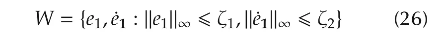
with ζ1and ζ2being some positive constants.
ProofBy substituting from(21)and defining ω=ν +J−1d={ωi}3×1,the closed-loop system dynamics(20)can be rewritten as follows:
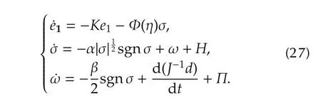
To facilitate Lyapunov based stability analysis,we will present the dynamics listed in(27)into a state-space form.To this end,the following state vector is introduced

where σiand ωidenote the i th element of σ and ω,respectively.Taking the time derivative of xi,it can be obtained that


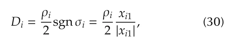
where ρiis some bounded functions that 0 ≤ |ρi|≤ 2δ3.Substituting from(30),(29)can be rewritten in a vector matrix format
where

and

Note that ifthen(for i= φ,θ,ψ),since Φi(η)is bounded(due to Assumption 3),thenIn view of(27),the convergence of e1iis guaranteed as well.Thus,the Lyapunov’s direct method is employed for the convergence of xi.After that,the stability analysis for e1iis presented.The Lyapunov function candidate Viis defined as
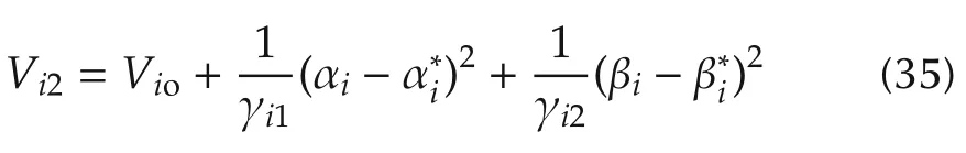
withbeing some positive constants.The nonnegative function Vioin(35)is defined aswhere
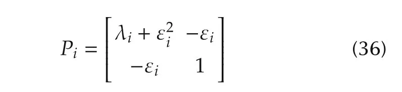
is positive definite if λi> 0 and εiare real number.Substituting from(31),the time derivative of Viocan be obtained as
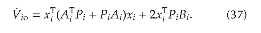
By substituting from(25),(33),(36),in(37)can be rewritten as
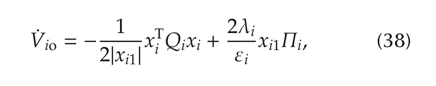
where
with
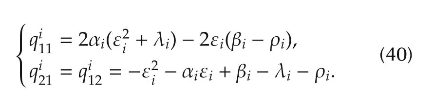
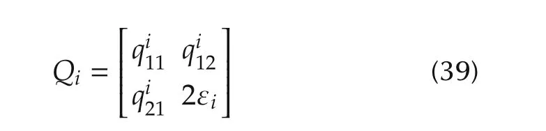
Substituting from(23),The matrix Qiwill be positive definite with a minimal eigenvalue λmin(Qi)≥ εiif
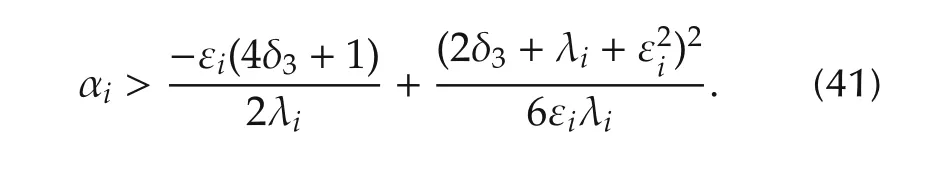

where(see proof in[17]).
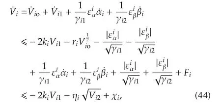
Taking the time derivative of Vi1and substituting from(27)yields
By substituting from(35),(42),(43),can be rewritten as follows:
The following two cases will be considered to obtained the result listed in Theorem 2.
Case 1Suppose that|σi| > μiand αi(t) > αim,∀t≥ 0.Then,in view of(22),we have
Selectingand differentiating(23),we obtain
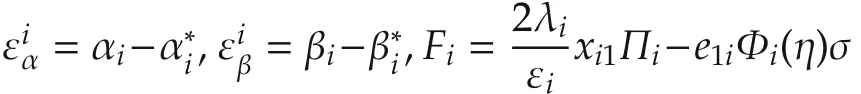
Substituting from(24),Fiis computed such that Fi≤0.Substituting from(45),(46),the first two terms on the right hand side of(44)are can celled.Thus,it is easy to have χi≤ 0 and

As soon as(41)is satisfied,σiconverges to the domain|σi| ≤ μiin finite time tFi(see Lemma 1 in the appendix).
Case 2Suppose that|σi|< μi,then the control gain αi(t)is reducing in accordance with(22)such that

Note the term Fiincluded in χibecomes−e1iΦi(η)σ,and in view of the structure of χiwhen substituting from(48),χibecomes sign indefinite as well as˙Viwhich comprises χi.
Thus,the above two cases forensure that after a finite time tFi,σiwill always stay in a domain|σi|≤ ρiwith ρi> μi(See the discussion presented in[17]).
In other words,σconvergesto the domain Wσin finite time tF=max{tFi}(for i= φ,θ,ψ)where

with||·||∞denoting infinity norm,ρ being defined as ρ =max{ρi}(for i= φ,θ,ψ).
Notice that Φ(η)={ϕi}3×3is bounded due to Assumption 3 such that|ϕi|≤ ξ,ξ > 0,we have the second term on the right side of(27)bounded such that|Φi(η)σ|≤ 3ξρ.Then,according to(27),we can conclude that e1iconverges to the domain|e1i|≤ 6ξρ/kias well as its time derivativeto the domainin finite time tHi(see Lemma 2 in the appendix).In other words,the finite time convergence of e1and its time derivativeto the domain W is guaranteed where
where ζ1=6ξρ/k,k=min{ki}for i= φ,θ,ψ,and ζ2=9ξρ.
4.2 Design of the altitude controller
To facilitate the control objective for the altitude channel of the quad rotor,the altitude tracking error signal ez(t)and its sliding mode manifold σz(t)are introduced as follows:
where λ is a positive gain.
By taking the time derivative of σz(t)and substituting(4)into the result,it can be obtained that
whereSimilar as the control development for the attitude controller τ(t),the altitude controller is designed as follows:
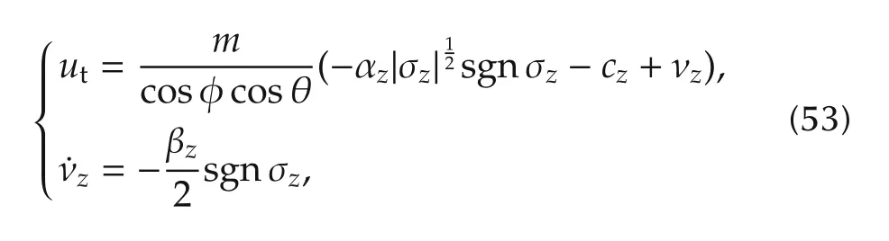
whereαzandβzare the adaptive gains with the following updating laws:

with εz,γz1,μzand pzbeing some positive constants.The parameter αzmdenotes an arbitrary small positive constant which is employed as the switching threshold value.
The main stability result of the adaptive altitude controller proposed in(53)is stated by the following theorem.
Theorem 3The proposed controller can drive ez(t)and its time derivativeto the domain Wzin finite time where Wzis defined as follows:

with ζz1and ζz2being some positive constants.
ProofThe proof of Theorem 3 can be completed by the following the similar steps for the proof of Theorem 2.
5 Experimental results
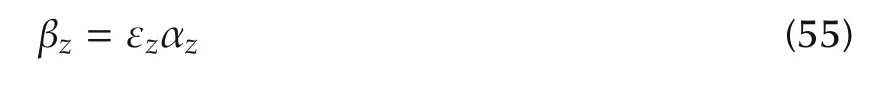
In this section,the proposed control strategy in Sections 3 and 4 is implemented on a self-built quadrotor helicopter flying testbed in an indoor environment to validate its performance as shown in Fig.2.The physical parameters of the quadrotor helicopter are listed in Table 1.The control loop runs at a frequency of 1kHz to ensure high performance of real-time response.
The nonlinear complementary filter proposed in Section 3 provides the altitude estimation information for the closed-loop operation.Its reliability is validated by a comparison between the estimated value and true value as shown in Fig.3.A OptiTrack motion capture system is employed to provide ground truth values for the quadrotor helicopter during the flighting test,these ground truth information is used only for the purpose of comparison,but not utilized in the closed-loop control.In Fig.3,ˆz(t)andˆv(t)represent the altitude estimation and vertical velocity estimation valuesobtained from the nonlinear complementary filter in(12),zr(t)and vr(t)represent the real altitude and vertical velocity values obtained from the motion capture system.From Fig.3,it can be seen that the maximum estimation error for the quadrotor’s altitude position is less than ±0.2m,and the maximum estimation error for the quadrotor’s vertical velocity is less than±0.18m/s.Considering about the fact that the accuracy for the direct altitude measurement from the onboard barometer is about±0.5m,the nonlinear complementary filter proposed in(12)has achieved a good accuracy for the altitude position and vertical velocity measurement.

Fig.2 Quadrotor helicopter flight testbed.
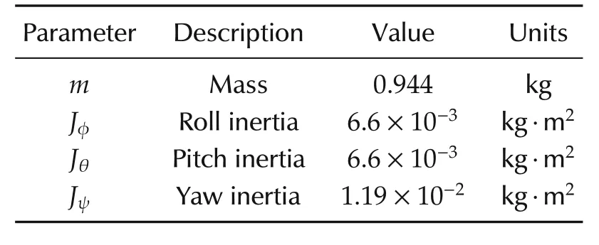
Table 1 Parameters for the quadrotor helicopter testbed.

Fig.3 Comparision between the estimation values(z(t),v(t))and real values(z r(t),v r(t)).
To validate the performance for the attitude and altitude controllers proposed in Section 4,a stabilization flight test is implemented on the quadrotor helicopter testbed.The control objective is to stabilize the quadrotor’s attitude angle(φ(t), θ(t), ψ(t))to be[φdθdψd]T=[0 0 0]T,and the quadrotor’s altitude z(t)to be some desired value as zd=1.94m.The quadrotor is first taken off manually to a proper position,and then the pilot flips the switcher on the RC controller to turn the quadrotor into automatic stabilizing control procedure,and the automatic control period lasts about 60 seconds.The control gains for attitude and altitude controllers are selected as follows for the best control performance:

Fig.4 shows the actual attitude response and its desired value.It can be seen that maximum stabilization error for the roll channel is about±1.1°,the maximum stabilization error for the pitch channel is about±0.8°,the maximum stabilization error for the yaw channel is about±1.2°,thus the proposed control strategy has shown good attitude control performance.The stabilization performance for the altitude channel is shown in Fig.5 whereˆz(t)is used as the closed-loop response for the quadrotor’s altitude position.It can be seen that the maximum altitude stabilization error is about±0.12m,and the maximum vertical velocity stabilization error is less than±0.12m/s,thus the proposed control strategy has achieve good altitude control performance for the quadrotor.From both Fig.4 and Fig.5,it can be seen that the quadrotor’s outputs(φ(t),θ(t),ψ(t),z(t))converge to their desired values very quickly.The adaptive control gains(αφ,αθ,αψ,αz)designed in(22)and(54)are depicted in Fig.6,they are all bounded.The control inputs(τφ,τθ,τψ,ut)are illustrated in Fig.7,they all stay with some reasonable values.
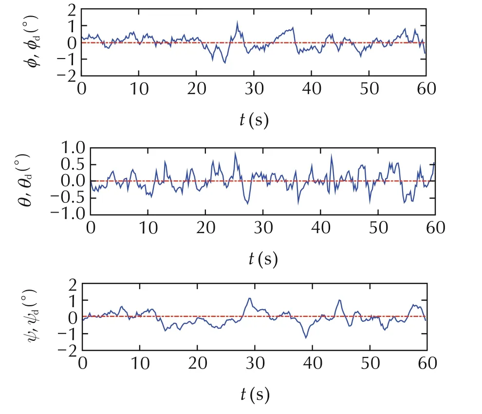
Fig.4 Actual attitude angles(φ(t),θ(t),ψ(t))and their desired values.
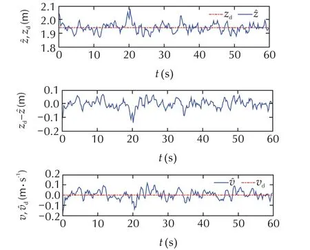
Fig.5 Actural altitudeˆz(t),vertical velocityˆv(t)and their desired value(z d,v d).
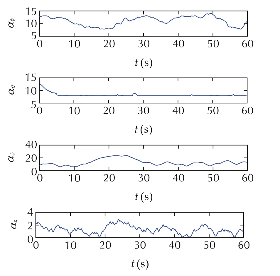
Fig.6 Adaptive gains(αφ,αθ,αψ,αz).
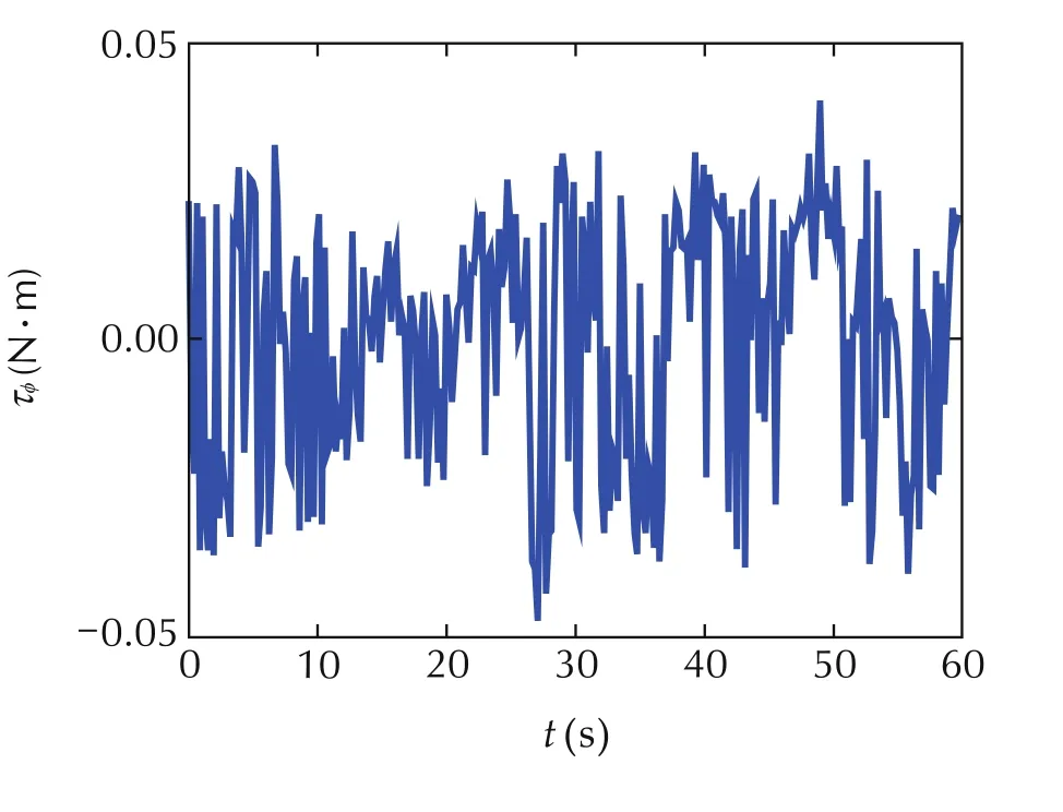
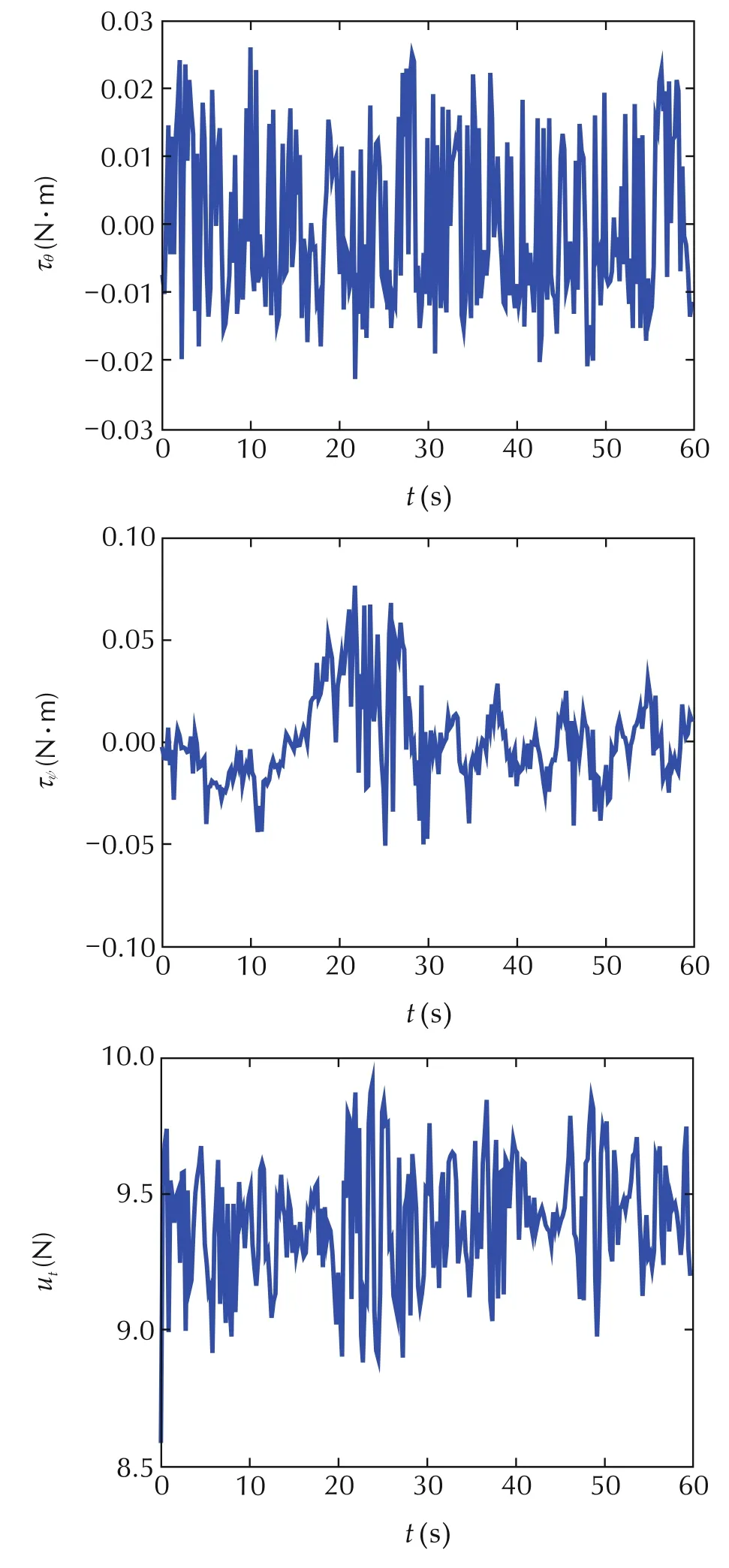
Fig.7 Control inputs(τφ,τθ,τψ,u t).
6 Conclusions
This paper considers the control problem for a quadrotor helicopter which is subjected to modeling uncertainties and unknown non vanishing external disturbances.The quadrotor’s roll angle,pitch angle,yaw angle,and altitude are selected as the system’s outputs.To improve the measurement accuracy for the altitude channel,a nonlinear complementary is developed and its convergence is proven.Based on the adaptive supert wisting scheme,a nonlinear adaptive controller for the quadrotor is developed and its finite time convergence is proven via the Lyapunov-based stability analysis.Realtime flight experimental results are presented to validate the performance of the proposed control strategy.Future work will focus on developing position controller together with the attitude controller for the quadrotor helicopter to achieve finite time convergence of the position tracking error under effects of parametric uncertainties and external disturbances.
[1]Y.Du,J.Fang,C.Miao.Frequency domain system identification of an unmanned helicopter based on adaptive genetic algorithm.IEEE Transactions on Industrial Electronics,2014,61(2):870–881.
[2]M.D.Hua,T.Hamel,P.Morin,et al.Introduction to feedback control of under actuated VTOL vehicles:a review of basic control design ideas and principles.IEEE Control System Magzine,2013,33(1):61–75.
[3]K.Alexis,G.Nikolakopoulos,A.Tzes.Model predictive quadrotor control:attitude,altitude and position experimental studies.IET Control Theory and Applications,2012,6(12):1812–1827.
[4]B.Zhao,B.Xian,Y.Zhang,et al.Nonlinear robust adaptive tracking control of aqua drotor UAVvia immersion and invariance methodology.IEEE Transactions on Industrial Electronics,2015,62(5):2891–2902.
[5]B.Xian,X.Zhang,S.Yang.Nonlinear controller design for an unmanned aerical vehicle with a slung-load.Control Theory&Applications,2016,33(3):273–279(in Chinese).
[6]W.Hao,B.Xian.Nonlinear fault tolerant control design for quadrotor unmanned aerial vehicle attitude system.Control Theory&Applications,2015,32(11):1457–1463(in Chinese).
[7]X.Zhang,B.Xian,B.Zhao,et al.Autonomous flight control of a nano quadrotor helicopter in a GPS-denied environment using on-board vision.IEEE Transactions on Industrial Electronics,2015,62(10):6392–6403.
[8]J.Toledo,L.Acosta,D.Perea,et al.Stability and performance analysis of unmanned aerial vehicles:quadrotor against hexrotor.IET Control Theory and Applications,2015,9(8):1190–1196.
[9]G.V.Raffo,M.G.Ortega,F.R.Rubio.An integral predictive/nonlinear H∞control structure for a quadrotor helicopter.Automatica,2010,46(1):29–39.
[10]R.Zhang,Q.Quan,K.Y.Cai.Attitude control of a quad rotor aircraft subject to a class of time-varying disturbances.IETControl Theory and Applications,2011,5(1):1140–1146.
[11]H.Ramirez-Rodriguez,V.Parra-Vega,A.Sanchez-Orta,et al.Robust backstepping control based on integral sliding modes for tracking of quadrotors.Journal of Intelligent and Robotic Systems,2014,73(1/4):51–66.
[12]H.Liu,Y.Bai,G.Lu,et al.Robust motion control of uncertain quadrotors.Journal of the Franklin Institute,2014,351(12):5494–5510.
[13]H.Liu,Y.Bai,G.Lu,et al.Robust tracking control of a quadrotor helicopter.Journal of Intelligent and Robotic Systems,2014,75(3/4):595–608.
[14]B.J.Bialy,J.Klotz,K.Brink,et al.Lyapunov-based robust adaptive control of a quadrotor UAV in the presence of modeling uncertainties.Proceedings of the American Control Conference,Washington:IEEE,2013:13–18.
[15]Y.Yu,X.Ding,J.Zhu.Attitudetracking control of aquadrotor UAV in the exponential coordinates.Journal of the Franklin Institute,2013,350(8):2044–2068.
[16]L.Derafaa,A.Benallegueb,L.Fridman.Super twisting controlal gorithm for the attitude tracking of a four rotors UAV.Journal of the Franklin Institute,2012,349(2):658–699.
[17]Y.Shtesse,M.Taleb,F.Plestan.A novel adaptive-gain supertwisting sliding mode controller:methodology and application.Automatica,2012,48(5):759–769.
[18]F.Kendoul,Z.Yu,K.Nonami.Guidance and nonlinear control system for autonomous flight of minirotorcraft unmanned aerial vehicles.Journal of Field Robotics,2010,27(3):311–334.
[19]B.Xian,C.Diao,B.Zhao,et al.Nonlinear robust output feedback tracking control of a quadrotor UAV using quaternion representation.Nonlinear Dynamics,2015,79(4):2735–2752.
[20]I.Gonzalez,S.Salazar,R.Lozano,et al.Real-time altitude robust controller for a quad-rotor aircraft using sliding-mode control technique.Proceeding of the International Conference on Unmanned Aircraft Systems,Atlanta:IEEE,2013:650–659.
[21]J.Hu,H.Zhang.Immersion and invariance based command filtered adaptive back stepping control of VTOL vehicles.Automatica,2013,49(7):2160–2167.
[22]R.Mahony,T.Hamel,J.M.Pflimlin.Nonlinear complementary filters on the special orthogonal group.IEEE Transactions on Automatic Control,2008,53(5):1203–1218.
杂志排行

Control Theory and Technology的其它文章
- Experimental evaluation of a real-time GPU-based pose estimation system for autonomous landingof rotary wings UAVs
- Ranging-aided relative navigation of multi-platforms
- Consensus controller for multi-UAV navigation
- Distributed output feedback stationary consensus of multi-vehicle systems in unknown environments
- Flocking control of a fleet of unmanned aerial vehicles
- Special issue on unmanned aerial vehicles(UAVs)