Ranging-aided relative navigation of multi-platforms
2018-06-04HaiLongPEIRuicanXIA
Hai-Long PEI,Ruican XIA
Key Lab of Autonomous Systems and Networked Control,Ministry of Education,China;
Unmanned System Engineering Center of Guangdong Province,Guangzhou Guangdong 510640,China;
School of Automation,South China University of Technology,Guangzhou Guangdong 510640,China
1 Introduction
Autonomous cooperative behaviors among unmanned systems excited tremendous interest in academic and industrialsocieties.Inter-platforms’precision navigation is much critical in a lot of teamed scenarios,such as sensing and avoiding,swarming,platooning,docking,autonomous landing,and autonomous aerialrefueling,all of which require access to the accurate relative orientation information between platforms in real-time.
For multi-platform relative pose determination,direct ranging is the most efficient measurement and is important in GPS denied circumstances[1],or in much demanding situations,such as the obit satellite clustering or constellation based joint earth observation in which more accurate inter-satellite baseline and precision relative attitude measure are needed[2].Fortunately,recent technology achievements,for example,laser ranging,RF(radio frequency)especially the UWB(ultra wideb and)devices[3],offer some new possibilities,but the corresponding algorithms are still underdeveloped.
Pairwise distance measurement has been used for decades for multi-anchor positioning,known as the multilateration,while seldom can we find they be used for relative pose determination.In the field of machine vision,researchers had suggested solutions to a similar relative pose problem[4,5],to configure the rotation and translation between different views of the same scenery.The general rotation transformation determination can be considered as the orthogonal Procrustes problem,or the Procrustes problem on the Stiefel manifold,which has received a considerable amount of study since the 1950s[6].One special case is the well known Wahba’s Problem[7,8]with a nonlinear,weighted least-squares performance index that seeks to obtain the optimal attitude matrix from a set of at least two independent vector measurements.This offers a possible direction on direct pose calculation[5],along which we feel more interested in developing efficient and dynamic algorithms by integrating this with the existing navigation technology.
One of the reasons that the Wahba’s problem has received significant attention is that it provides a globally optimal solution and it does not make any linearization or small angle approximations,this is successfully applied in the spacecraft attitude estimation and control.As the workhorse of aerospace estimation,the extended Kalman filters(EKFs)is a recursive estimator[9]while the solution to the Wahba problem provides single point attitude estimates.There has been some work on the recursive consideration of Wahba’s solution[10],to make the solution suitable for practical application.This paper tries to integrate these two algorithms to generate smooth relative pose estimation with pairwise range measurement between platforms.
The rest of this paper is organized as follows:The relative motion kinematics is modelled in Section 2,within which the inertial measurement unit(IMU)measuring and pairwise ranging are also discussed.In Section 3,pairwise ranging based inter-body orientation and translation estimation as well as the error covariance analysis are deduced,after the review of Wahba’s Problem.Section 4 illustrates the EKF design procedure,to fuse estimated pose with the IMUs data to generate smooth relative navigation output.In Section 5,the on-going construction of a testbed is described and the promising preliminary experiment result is discussed also.We have the further discussion and conclusion in Section 6.
2 Relative motion and observation
Consider two platforms(Fig.1),Leader L and Follower F,equipped separately with two sets of sensors,sensor set{ai},i=1,...,M mounted in body L and sensor set{bj},j=1,...,M mounted in body F.The sensor topologies are perfectly known in the body reference frames.For simplicity,let ai,bj∈ R3×1represent the known position vectors with reference separately to the body frames of L and F.The pairwise distances between sensors of the two sets can be sampled in real time,and the IMUs are mounted at the mass centers of each body with acceleration and angular velocity measuring outputs in high frequency.

Fig.1 Relative move of two-platforms.
2.1 Relative motion kinematics
Define the unitary quaternion aswithqTq=1,where e ∈ R3×1and θ∈ R are the Euler axis of rotation and rotation angle.The attitude matrix Q∈SO(3)where SO(3)represents the special orthogonal group,can be written as a function of the quaternion[7]

where


with the cross product

The quaternion products⊗and⊙are given as

andis the quaternion inverse.
Let qland qfrepresent the attitude quaternions with respect to the inertial frame of the leader and follower.The relative quaternion qf|land corresponding attitude matrix,which are used to map vectors in the leader frame to vectors in the follower frame,are defined by

The attitude kinematic is given by

whereis the angular velocity of the body frame with respect to the inertial frame given in body frame coordination,andis the attitude matrix that converts vectors from the inertial frame to the body frame.The relative position vectorwith respect to the frame of Leader,between Leader L and Follower F,is defined as

whereandare inertial positions of Follower F and Leader L with respect to their own frames separately,converts the vectors from the inertia frame to the follower body frame,andsatisfies[11]

The quaternion kinematics is given by

where

is the relative angular velocity,defined by

withandare inertial angular velocities of Follower F and Leader L with respect to their own frames separately.
2.2 Sensors and measurement
There are two types of measurements:output from the IMUs installed in the mass center of the two bodies,and pairwise distance measurement from the two separate sensor sets mounted on the surfaces of body L and body F.We need to estimate the relative orientation and distance from the pairwise ranges sampled,and further to fuse these estimates with the output data from the engaged IMUs.
Inertial measurement
The inertial measurement units can generate acceleration and angular velocity vectors with reference to the corresponding body frames which are located in the mass centers of the corresponding platforms.The output signals are usually corrupted with noises,drifts and biases.
For the inertial measurement of Leader L,the acceleration measurement model is defined as[7,9]

whereis the true acceleration andis the accelerator’s measurementis the accelerator’s bias,ηlav∈ R3×1and ηlau∈ R3×1are supposed to be i.i.d.zero mean white random process with covariancesand
The angular velocity(gyro)measurementhas a similar model[7,9]

where βfg∈ R3×1is the gyro bias, ηfgv∈ R3×1and ηfgu∈ R3×1are i.i.d.zero mean white random process with variancesand
For the IMU mounted in the body F,the accelerator and gyro measurement models ofandare similar to(14)and(15).
Pairwise ranging
As mentioned in the introduction,it is suggested that pairwise ranges are sampled between two sensor sets located at the leader and follower separately.The pairwise ranging measurementbetween sensor aiand sensor bjcan be described as

where

is the pairwise Euclidean distance and eijis the measurement noise assumed as an i.i.d.zero mean white random process with variance
3 Relative attitude and distance estimation
3.1 Range based relative pose problem
For simplicity,letrepresent the relative rotation matrix from the frame of body L to the frame of body F,satisfying QTQ=I andrepresent the body frame translation vector from L to F,shown in the reference frame of body F.With the rigid body transformation[10],the position of sensor aiin the reference frame of body F can be denoted by

and so all sensor locations of body L in the reference frame of body F can be expressed as

where Y=[y1,...,yM],and A=[a1,...,aM].
From the above analysis(16)and(17),joint estimation of the relative orientation Q and translation t can be considered as the solution of

which is a complicated nonlinear constrained optimization problem.One possible method is to introduce the solution of Procrustes problem on the Stiefel manifold[6],or equivalently,the solution of Wahba’s Problem[7,8],which may be more suitable to generate the quaternion as well as the corresponding covariance for the kalman filter design afterwards.The existing Wahba’s problem solution usually can only figure out the rotation,we need to decompose the complex multivariable optimization of(20)into suitable forms,with which the rotation and translation can be computed in steps.
3.2 Review of Wahba’s problem
Wahba’s problem
The original Wahba’s problem[7,8]seeks to determine an orthogonal matrix Q with determinant+1 that minimizes the loss function

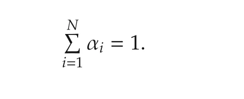
where{Wi}is a set of N unit vectors measured in a platform’s body frame,Viare the corresponding unit vectors in another reference frame,and{ai}are nonnegative weights satisfying
By parameterizing the rotation matrix Q with its related quaternion q,the gain function can be expressed as
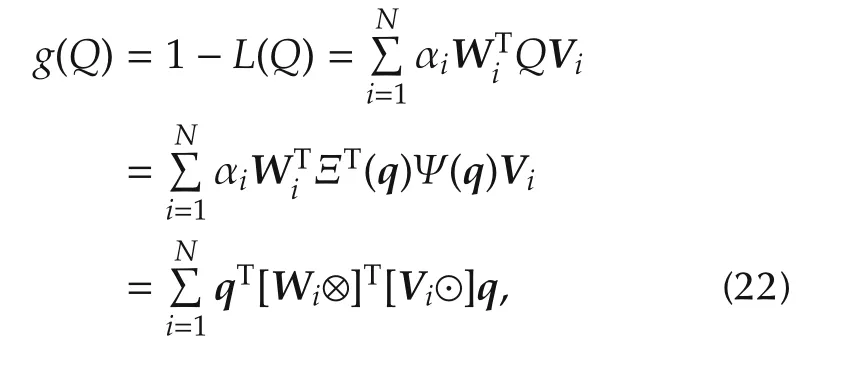
where⊗and⊙are quaternion products as illustrated in(5).
The so-called q-method[7,8]transforms this problem into the quadratic maximization problem

where

with
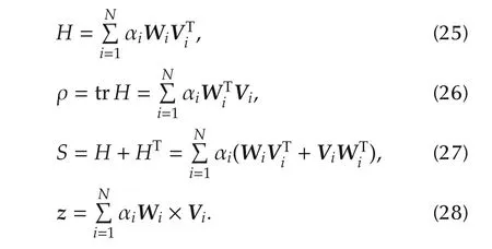
The gain function g(q)will be maximized if qoptis chosen to be the eigenvector of K belonging to the largest eigenvalue of K,

Covariance analysis
The estimated quaternionˆq will be used as the relative attitude observation,its probability distribution is important in filter design afterwards.
The true quaternion can be described as the product of an error quaternion δq and the estimate[7,8,12]

where qtrue,δq,andare all properly normalized unit quaternions,δϑ ∈ R3×1is the error vector of rotation.δq can be approximated as[7,12]

which could be assumed to be unbiased,i.e.,

holds for the scalar component of δq to order E{|δϱ|2}.
The 3×3 quaternion covariance matrix is defined as

If δ is a small quantity of the error of observation δq or the angle of rotation δϑ,for the easy analysis of errors the reference frame coincides with the body frame,then from(21)–(29),we have

where

According again to(21)–(29),we have

which can be reformulated as,by considering(34)

and further

Considering

we have

where

Define σtotsatisfying

which leads from(38)

The quaternion covariance matrix can be deduced[7,8]

Furthermore,for an observation t∈ R3×1

where Q is the rotation matrix in(21)and a,c ∈ R3×1are known vectors,similar to(30)the true rotation can be described as the product of an error rotation δQ and the estimation

whereδQ can beexpressed in term of the rotation vector

Then we have the expression of observed error

and the observation error covariance

where the coefficient 4 in the front of the last term can be derived from(31).
3.3 Attitude and distance estimation
The original Wahba’s problem solution generates the relative attitude by observing unit vectors from two different frames.It concerns only the rotation of the frame.For pairwise ranging of two bodies,the measurement contains the blended information,including the relative attitude as well as the relative distance.We need to configure some orthogonal(isometric)transformations to decompose the information into two sets.
Attitude and distance caclulation
Isometric transformations are constructed in this subsection so that the existing Wahba’s solution[7,8]as well as the covariance analysis can be introduced to directly estimate the attitude,instead of solving the original complicated nonlinear optimization problem(20).
From the pairwise range measurement(16)

we have the squired range measurement

with.To eliminate the non-zero mean(usually could be omitted approximately for its high orders),we introduce

where

that gives

where

are known,and

By repeating all i∈[1,...,M],we write(50)in matrix form

where°is the Hadamard product,and

By introducing a matrix is ometry decomposition,

whereandThe termin(50)can be decomposed by left-multiplyingwhich can be reformulated as

with

By introducing another matrix isometry decomposition

withand,the translation t in therigid body transformation(19)can beeliminated,

that reformulates(53)as

Then,on the existence assumption of the pseudoinverse[·]†of the matrixwhich could be considered as an optimal sensor placement problem.We finally deduce from(56),

where

which converts the original nonlinear constrained optimization problem(20)to a Wahba’sproblem(21)shown as:

The q-method algorithm(23)–(29)is engaged to calculate the quaternion efficiently,instead of the rotation matrix solution.Let

the pairwise ranging based attitude estimationˆq can be calculated with the q-method algorithm shown as

where

with
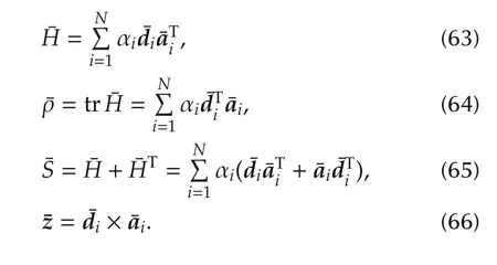
With the estimated relative quaternionˆq,the relative distance between Leader L and Follower F can be deduced as follows.
From(19)we have

where Y can be deduced from(53)

By substituting the calculated attitudewith the estimatedas shown(1),the resulted translationcan be computed as

Error covariance analysis
One merit of Wahba’s problem quaternion solution is that the estimation error covariance can also deduced with the existing algorithm.By comparing the Wahba problem formulation(21),or equivalently(23),with the properly transformed measurement expression(57),the error distribution of the solution(41)is

with
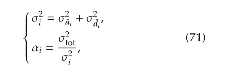
wherebeing deduced from(58)andcan be deduced from(51),(57)and(58),with the assumption of higher order of errors of E in(57).From(30)

we have

and then

The variance of estimation errors ofˆq is deduced as

For the translation observation(69)

by comparing with(46)and omitting the higher order of errors E,the resulted error distribution of estimated distanceˆt is derived as

4 The extended Kalman filter design
In this section,a loosely coupled extended kalman filter is configured to implement the smooth output of the relative attitude and distance.The filter configuration is rather similar to the work in[7,9],but with different observation method.The estimated unitary quaternion as well as the translation from the sampled pairwise ranging measurement can be directly introduced to the quaternion based kalman filtering.We will describe only the necessary linearized state-error dynamics here in this section.
The states of interest in this EKF are quaternion represented relative attitude,relative position,relative velocity,and biases on all the inertial acceleration and angular velocity measurements:

and the estimate equations are from the truth equations in Section 2,

Considering

ϱ is the vector part of the quaternion and the variance of the scalar entity q0could be considered tiny,the stateerror vector can be shown as

With the relative navigation equations(7)–(9),(11)and(12),the overall linearized error dynamics are governed by the equation[11]

where the process noise vector consists four Gaussian noise terms

with the noise covariance matrix

and
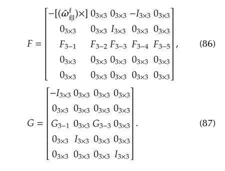
Here,F3−i,i=1,...,5 and F3−j,j=1,3,are corresponding entities derived from the navigation equations(75)–(80),

The observation of this filter is the estimation of the relative quaternion(61)and the relative translation(69),with the deduced covariance(72)and(73).

The measurements of this filter are the relative angular velocities and the relative acceleration,which can be transformed from the outputs of two IMUs,or IMU sets,located in two platforms.The formulas as well as the iteration algorithm is quit similar to the standard EKF design[7,9].
5 The experiment verification
5.1 Testbed setup
A testbed is configured in our lab to testify the fidelity of the proposed algorithm.The experiment is conducted in this stage to implement a planar relative translation as well as orientation estimation(Fig.2).

Fig.2 Relative navigation of two-platforms moving in a plane.
As shown in the figure,two identical square platforms are constructed with light frames.One platform is fixed on a table and the another one is mounted on a motorized turntable with the block moving along an electric slide rail on the table,so that two platforms can simulate accurately the relative translation and rotation movement.The side length of each square platform is 50 cm.
A kind of precision ultra wide band transceivers,the P440 modules from Time domain[3],are engaged as the sensor nodes,accompanied with a customized sister board with embedded high computation and wireless data communication(ZigBee)capability(Fig.3).An IMU chip is also mounted on the sister board to offer strap down acceleration and gyro output in high frequency.Each node is a self-contained system without any wired connection with other modules,and all the sampled data are transmitted to a host PC for on-site processing.

Fig.3 Modified UWB sensor node.
Each platform is equipped with 3 nodes at the different corners,implementing 3×3 pairwise range measurements between two platforms.Every pairwise ranging error(16)is assumed i.i.d.Gaussian with a given covariance

The two sets of UWB modules are synchronized to implement the 3×3 pairwise range measurements at the same time.This is configured with the Range Net protocol supplied from Timedomain[13],and the time cycle of sampling is lowered to 0.4 s.
The inertial measurement on the mass center can be approximated by the averaged sum of the outputs of two non-adjacent IMUs(with the same error variance)located at the symmetric corners.The IMU measurement noise(14)and(15)is assumed i.i.d.Gaussian also with the given variance

5.2 Experiment design and result analysis
With the above mentioned testbed setup,a planar two-body relative move is designed to verify the fidelity of the proposed ranging based pose estimation algorithm.The relative rotation is implemented via swiveling the rotatable platform in the plane with the given angular changing with time shown as

and meanwhile keeping zero translation movement.With the sampled pairwise ranging data,the relative orientation quaternion is determined by the modified q-method(61),and the estimation is shown as Fig.4.

Fig.4 Quaternion estimation.
For the reason of planar rotation,the first two components of the estimated quaternion are almost zeros.
Fig.5 shows that with the estimated quaternion,the calculated relative rotation is rather noisy(the blue line),after fusing with the IMUs’data,the EKF filtered quaternion gets smooth and resulted rotation estimation(the red line)is rather feasible.

Fig.5 Orientation smoothing with quaternion EKF filtering.
Fig.6 shows that with the estimated quaternion,considering the modified error¯E in(58)be small,the calculated translation disturbance is within±5cm,which is already acceptable and could be even approved if fusing with the accelerator output.
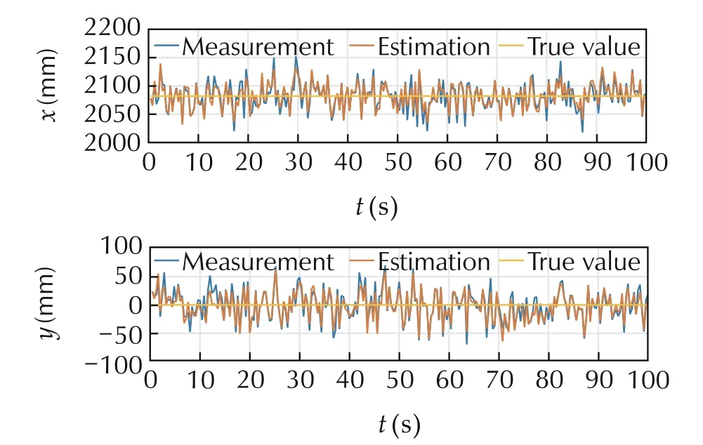
Fig.6 Orientation smoothing with quaternion EKF filtering.
6 Discussion and conclusion
This paper presents the on-going progress on the relative navigation of rigid bodies with pairwise range measurement.The relative rotation and translation estimation is integrated directly with the kalman filter to generate smooth relative location and orientation.A simple testbed is being constructed for further demonstration,while preliminary experiment has shown some promising result.
[1]D.O.Wheeler,D.P.Koch,J.S.Jackson,et al.Relative navigation of autonomous gps-degraded micro air vehicles.All Faculty Publications.Provo:Ira A.Fulton College of Engineering and Technology,2017:https://scholarsarchive.byu.edu/facpub/1963.
[2]G.Di Mauro,M.Lawn,R.Bevilacqua.Survey on guidance navigation and control requirements for spacecraft formation-flyingmissions.AIAAJournalof Guidance,Control,and Dynamics,2018,41(3):581–602.
[3]Time Domain.PulsON 440 Module:http://www.timedomain.com/products/pulson-440/.
[4]B.K.P.Horn.Closed-form solution of absolute orientation using unit quaternions.Journal of the Optical Society of America A(Optics and Image Science),1987,4(4):629–646.
[5]D.W.Eggert,A.Lorusso,R.B.Fisher.Estimating 3-D rigid body transformations:A comparison of four major algorithms.Machine Vision and Applications,1997,9(5/6):272–290.
[6]L.Elden,H.Park.A Procrustes problem on the Stiefel manifold.Numerische Mathematik,1999,82(4):599–619.
[7]F.L.Markley,J.L.Crassidis.Fundamentals of Spacecraft Attitude Determination and Control.New York:Springer,2014.
[8]M.D.Shuster,S.D.Oh.Three-axis attitude determination from vector observations.Journal of Guidance,Control,and Dynamics,1981,4(1):70–77.
[9]J.L.Crassidis,J.L.Junkins.Optimal Estimation of Dynamic Systems.2nd ed.Boca Raton:CRC Press,2012.
[10]A.Thomas,Z.Renato,C.John,et al.Q-method extended Kalman filter.Journal of Guidance,Control,and Dynamics,2015,38(4):752–760.
[11]A.M.Fosbury,J.L.Crassidis.Relative navigation of air vehicles.Journal of Guidance,Control,and Dynamics,2008,31(4):824–834.
[12]L.Dorst.First order error propagation of the Procrustes method for 3D attitude estimation.IEEE Transactions on Pattern Analysis and Machine Intelligence,2005,27(2):221–229.
[13]S.P.Chepuri,G.Leus,A.J.Van der Veen.Rigid body localization using sensor networks.IEEE Transactions on Signal Processing,2014,62(18):4911–4924.
杂志排行
Control Theory and Technology的其它文章
- Flocking control of a fleet of unmanned aerial vehicles
- Distributed output feedback stationary consensus of multi-vehicle systems in unknown environments
- Consensus controller for multi-UAV navigation
- Nonlinear robust control of a quadrotor helicopter with finite time convergence
- Experimental evaluation of a real-time GPU-based pose estimation system for autonomous landingof rotary wings UAVs
- Special issue on unmanned aerial vehicles(UAVs)
