Numerical simulation of the self-propulsive motion of a fishlike swimming foil using the δ+-SPH model
2018-05-19PengNnSunAndreColgrossiMnZhng
Peng-Nn Sun, Andre Colgrossi, , A-Mn Zhng,*
a College of Shipbuilding Engineering, Harbin Engineering University, Harbin 150001, China
b CNR-INSEAN, Marine Technology Research Institute, Rome, Italy
Fishes are very smart swimmers in water. Fishes are able to make full use of the flows around their bodies, saving forces, and obtaining the optimal hydrodynamic performance [1]. So far the man-made underwater vehicle is very difficult to swim in such a high efficiency like a fish. Humans still need to learn a lot form animals.
Fishlike swimming has been a classic hydrodynamic problem which attracts the attention of researchers for a long history[2–5]). Many works has been done, trying to explain the mechanism of swimming propulsion of single fish [6–8] and the reason of fish schooling [5, 9, 10]. The fishlike swimming problem also has many applications in the field of naval architecture and ocean engineering. One remarkable application is in the propulsion of marine vehicles. The swimming propulsion or bionic propulsion can have higher efficiency than the using of screw propeller and can avoid the problem of hydroacoustic noise and cavitation erosion. Recently, with the rapid development in the research of underwater vehicles, many of them are designed to have a fishlike shape, use a swimming propulsion and therefore have superior stealth property.
In the early years, the study of fishlike swimming hydrodynamics are mainly based on experimental observations [3].Recently as the development of the computational fluid dynamics (CFD), the investigations based on the numerical models are also rapidly growing. One representative numerical method is the immersed boundary method (IBM) which uses a Lagrangian boundary to track the surface of the rigid or deformable structure with complex shapes [11]. With the hybrid of IBM and other Naiver–Stocks solvers, fishlike swimming problems have been modeled for both two dimensional (2D) [9, 10, 12] and three di-mensional (3D) cases [13].
To the best of our knowledge, there are still very few publish papers modeling fishlike swimming problems using mesh-free or particle methods. One of the most widely used particle methods in the study of fluid dynamics is the smoothed particle hydrodynamics (SPH) method [14, 15]. Similar to IBM method,SPH also has the advantage of solving fluid-structure interaction(FSI) problems characterized by moving boundaries with large deformations [16].
In the traditional works, when investigating the self-propulsive swimming bodies, the swimmers are fixed in an uniform incoming free stream with a fixed inflow velocity. The hydrodynamic forces on the swimming body are measured. When the streamwise force becomes negative, the fish is considered to be able to swim forward with a speed larger than the inflow velocity. This investigation method is named as Approach 1 in this work. Approach 1 has been adopted in Deng et al. [9] and Dong and Lu [10] to study the hydrodynamic performance of a single fish and the interactions between two fishes in different relative locations. However, strictly speaking, the hydrodynamic state of the flapping fish fixed in a stream is different to the one swimming freely in the still fluid (Approach 2). In the former case, the fish is constrained by a varying external force to make it remain in its location, while in the latter case, the fish stays in a situation that the propulsive force, drag force, and inertia force reach a dynamic balance.
The theoretical model of the real self-propulsion under Newton's law has been proposed from the end of last century by Carling et al. [17]. In that work, 2D anguilliform swimming was modeled using the finite difference method (FEM) and advantages of allowing for acceleration and deceleration of the swimmer's body were demonstrated. Yang et al. [12] extended the theoretical model of Carling et al. [17] and 2D simulations in the framework of finite volume method (FVM) were performed. This model has been further extended into 3D problems regarding the fast-start swimming and fish's body-shape optimization by Xin and Wu [18, 19].
In the present work, Yang's self-propulsion model [12] has been applied in the framework of a particle method. The recently developed-SPH model [20] is adopted to model the self-propulsive fishlike swimming problem and investigate the speedability of the swimming foil with different flapping parameters. In order to understand the mechanism of the thrust force generated in different swimming conditions, the vortical structures in the flow field can be detected by Eulerian definitions, e.g. vorticity or Q criterion. Finite-time Lyapunov exponent (FTLE), which is a Lagrangian definition used to reveal Lagrangian coherent structures (LCSs), can also be calculated and it helps understanding the flow physics in a Lagrangian way [21].Recently, 3D LCSs have been reveled by Kumar et al. [22] in the FTLE field and the latter has been shown to be a reliable tool to study the relationship between the thrust generation and the wake structure behind a pitching panel. As emphasized in Ref.[23], the Lagrangian nature of SPH method provides greater convenience than the Eulerian CFD solver in detecting LCSs through the calculation of FTLE field.
Similar to Deng et al. [9], Dong and Lu [10], and Yang et al.[12], a NACA0012 foil is adopted to mimic the backbone undulation of a swimming fish. The midline of the NACA0012 foil is designed to undulate according to the following formula:

whereis the vertical oscillating magnitude andis the local horizontal coordinate starting form the foil head to the tail and therefore we have 0 ≤ x′≤ L whereis the length of the foil.The wave number iswhere the wave lengthis equal tounless otherwise specified. The streamwise travelling wave propagates with a constant phase speed asis the phase angle of the wavy foil. A (x′) is the oscillating amplitude depending on the local horizontal coordinate on the foil.is usually determined by the swimming characters of different fishes [24].
Generally two approaches can be adopted to investigate the hydrodynamic performance of swimming bodies. In Approach 1,the swimming body flaps in a free stream but its location is constrained on a fixed position by an external force, see the left part of Fig. 1. The free stream with a steady velocity ofenters from the left side of the fluid domain. The fluid domain is designed with the width ofin order to avoid the blockage effect from the lateral walls on which a free-slip boundary condition is imposed. The fish is placedaway from the in-flow boundary and the total length of the fluid domain iswhich is large enough to avoid the effect of the out-flow boundary. The hydrodynamic force on the swimming body is measured and if the drag force coefficient is negative, it means the swimmer can move forward with a speed larger than the inflow velocity.
In Approach 2, the swimming foil is able to move forward under the thrust force, see the right sketch in Fig. 1. According to the self-propulsion model proposed by Carling et al. [17] and further extended in Ref. [12], the governing equations of the fish motion can be written as

Fig. 1. Sketches for the fluid domain and the placement of the fishlike swimming foil in different investigation approaches. Plot a shows the concept of Approach 1, where the fish is fixed in an incoming free stream; plot b shows the concept of Approach 2, in which the fish is self-driven to swim forward in a still fluid field.

whereanddenote the mass and the instantaneous moment of inertia about the centre of mass (c.m., denoted by subscript).andrepresent the linear and angular velocity with respect to c.m.andare the total external force and the total external torque with respect to c.m. Through the solving of Eq. (2), self-propulsive motions of the swimming body can be realized. In this case, the force balance can be reached among the drag force, the thrust force, the inertia force and so on. A comparative study for the results of Approach 1 and Approach 2 will be given later.
The recently developedscheme [20] is adopted to solve the physical problem described before.scheme avoids the problem of particle disorder and therefore allows a very smooth vorticity field in the numerical results [23]. The tensile instability is also prevented in this scheme thanks to the tensile instability control (TIC) [25].
The governing equations of thescheme are written as [20, 26, 27]:
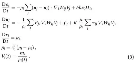
The quantities,,,, anddenote respectively the density, the mass, the volume, the velocity, and the position associated with the i-th particle.
The quantity Wij=W(|i-j|;h) represents the Wendland C2 kernel withwhereis the initial particle spacing.is the dynamic viscosity andwhereis the number of spacial dimensions of the problem. The artificial speedis set equal towhereis the reference velocity. In this work, the inflow velocity has been used as the reference velocity in the simulations of both Approach 1 and Approach 2.is the reference density when the pressure is zero.is the body force which has been set as zero in the present study.
In Eq. (3), the forms of the diffusive termand the viscous termcan be referred to Refs. [20, 26, 27]. Specifically, the parameter ofis adopted in the density diffusion.
Generally in classic SPH models,is written as[15]. However, in order to completely prevent tensile instability, a switch correction named TIC proposed in Ref. [25] is adopted withbeing written as TIC is able to completely prevent the tensile instability when the pressure becomes negative and the PST presented later can help to reduce the non-conservation of momentum generated by TIC term [25].

In Eq. (3), a particle repositioning is performed at the end of each time step as [25]

whereis evaluated as

This formula is similar to the PST in Ref. [28] but in a weakly compressible form. PST is helpful to obtain a smoother vorticity field [23]. Here thenumber is 1.5 since the forth order Runge–Kutta time integration is adopted.is the Mach number equal to. The parametersandare used to obtain an efficient regularization of the particle distribution when the smoothing length is relatively large(). The evaluation of the time step,, used in the forth order Runge-Kutta time integration, can be referred to Ref. [20].
In the present work, in order to accelerate the computational speed, the technique of adaptive particle refinement (APR) [29]has been adopted. Further, the improved version of APR [30] has been adopted here. In this technique, the distribution of the switched off particles has the possibility to be disordered since their velocities are interpolated from the fluid particles of the finest resolution using a Shepard kernel, but thanks to the PST nested in thescheme, the switched off particles are regularized in each time step. Therefore we can say, on one hand,APR improves the efficiency ofscheme; on the other hand,scheme also improves the robustness of APR [31].
The inflow and outflow boundary conditions presented in Ref. [32] are adopted here to model the free stream condition when the Approach 1 is used. The particle packing algorithm proposed in Ref. [33] is adopted at the initial stage of the simulation, in order to uniformly arrange the fluid particles around the wavy foil.
Regarding the implementation of lateral solid wall boundaries, the "fixed ghost particle" technique presented in Refs. [26,34] is implemented in this work and a free-slip boundary condition is imposed. The flapping foil is modeled also using the"fixed ghost particle" but with a no-slip boundary condition applied. The ghost particles of the foil undulate according to Eq. (1)presented before. The pressure interpolation from the fluid to the ghost uses the Shepard interpolation as adopted in Ref. [35].
Regarding FSI algorithm, the conventional parallel staggered(CPS) algorithm presented in Ref. [36] is applied. Since here the time step for the weakly compressible SPH is relatively small, a satisfied numerical stability is allowed within this FSI coupling strategy. The forces on the foils are measured by summating the interacting forces between the fluid particles and ghost particles[37], [38]. The governing equations for the motion of the selfpropulsive wavy foil (see Eq. (2)) are also integrated using the Fourth order Runge–Kutta integration scheme.
Since thescheme has been full validated in Refs.[20, 25] for viscous flows around bluff bodies with different irregular shapes and in different Reynolds numbers, benchmark val-idations will not be presented. And it is noted that we only focus on the forward propulsive speed of the swimming foil and therefore the transversal and rotational motions of the foil are ignored. The transverse and angular velocities due to the tail flapping of the foil are left for the future studies.
In all the simulations, in the far field, the particle resolution is, and the particles are gradually refined when they approach the flapping foil and de-refined when they leave far away [20, 25]. In the presentation of the results, the inflow velocity, the fluid density, and the foil lengthare used to nondimensionalize the other variables. The mass of the foil in Approach 2 is set as M =0.12ρL2. The Reynolds numbers of all the cases are set as. In the numerical calculation,=1 m/s,= 1 kg/m2, and= 1 m are used in the present study.A linear ramp with a constant acceleration is used for gradually increasing the inflow velocityand the oscillating amplitudeuntil the preconcerted values in order to avoid an impulsive start of the velocity field.
The oscillating amplitudeis written as

where,, andare three different coefficients solved from the kinematic data of a steadily swimming fish [24]. In the determination of the oscillating amplitude of the foil,, andare adopted in order to ensure. The phase speed is set as cp=2U where U is the inflow velocity as stated before. The numerical results for the simulation of fishlike swimming problems are modeled using both Approach 1 and Approach 2.(1) In Approach 1, the swimming foil is fixed in a free stream(2) In Approach 2, the swimming foil is self-driven to move forward under the thrust force.
In Ref. [25], a numerical validation has been conducted for the viscous flow past wavy foil at Reynolds numberusing Approach 1. The hydrodynamics forces on the foil were proven to agree fairly well with the solution by a Naiver-Stocks solver [10]. Here the results solved by Approach 2 are shown firstly and will be compared with the results of Approach 1.
Firstly, four different particles resolutions on the foilare adopted for the simulation to check the convergence of the results in Approach 2. Time evolutions of the fish movement and the swimming velocity are plotted in Fig. 2. In the presentation of SPH results, x and y denote the horizontal and vertical positions of the fish and the subscriptstands for the initial positions at. The minus sign means the foil swims from the right side to the left. As the particle resolution is refined, the terminal velocity converges to uterminal=-1.23U. After a compromise between computational costs and numerical accuracy, in the following part of the paper, the particle resolution L/Δx=200 on the foil will be used for the other numerical investigations.
As shown in Fig. 3, the vorticity contours at three different time instants are depicted. During the accelerating stage, the vorticity generated by the flapping foil deflects to the upper part of the flow region. After the swimming velocity reaches the terminal stage, the distribution of vorticity locates in a straight line behind the foil.
In the following part, the numerical results solved by Approach 1 and Approach 2 will be compared. Firstly, the drag force coefficients () whereis the drag force measured on the foil) are compared. Results from both Approach 1 and Approach 2 are plotted in Fig. 4. In Approach 1,during the steady stage, the drag force is almost always below zero, that means under such a phase speedand flapping amplitude, the foil can reach a terminal speed larger than. In Approach 2, after a transitional stage, the drag force oscillates around zero. That is due to the magnitude of the terminal velocity uterminal=-1.23U is larger that, the magnitude of the thrust force and the drag force reaches a dynamic balance.
The vorticity contours behind the foil solved by the two approaches atare compared in Fig. 5. Further, LCSs are reveled through the calculation of FTLE field [23] in the SPH results. The ridges of the FTLE field clearly show the boundaries of the vortices. The setting up of a threshold to locate these boundaries (as in the vorticity field) is not necessary in FTLE field. The convenience in detecting the LCSs is one of the superiorities of SPH compared with other Eulerian CFD models. The vortex structures, presenting a shape of the reverse von Karman vortex street, are similar in the two approaches, which means that both the two methods are applicable for the investigation of the flow features in this kind of problem.
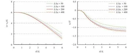
Fig. 2. Time evolutions of the fish movement and the swimming velocity of the fishlike swimming foil in four different particle resolutions.
In conclusion, Approach 2 is easier to give the terminal swimming velocity, while for Approach 1, several numerical trials are generally needed to adjust the inflow velocity, ensure the drag force oscillating around zero and then obtain an accurate prediction of the terminal swimming velocity. In the rest of the paper, Approach 2 will be only adopted to investigate the propulsive performance of the fishlike swimming foil in different flapping parameters.
The thrust force generated by the flapping motion of the foil is tightly related to the phase speed. The effect of the phase speed on the terminal swimming speed is investigated. Results of three different phase speeds,, andare compared. In all the cases, parameters, and, which lead to, and, are adopted in the determination of the oscillating amplitude.
Time evolutions of the fish movement and the swimming velocity are plotted in Fig. 7. The swimming foil accelerates at the initial stage and then reaches a steady terminal velocity. As the phase speed is increased, the magnitude of the terminal velocity improves accordingly. The vorticity contours behind the swimming foil at the same time instantsfor the three phase speeds are depicted in Fig. 8. At a small phase speed, the reverse von Karman vortex street behind the foil has a regular structure. In each flapping period, two single vortices are shed(2S mode). As the phase speed is increased, the reverse von Karman vortex street starts to be disturbed and in each period, the number of vortices shed are increased.
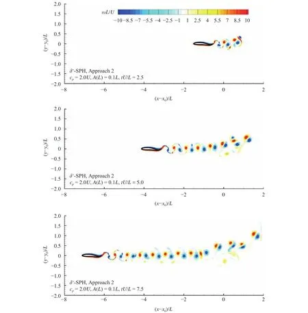
Fig. 3. Vorticity contours at three different time instants during which the fishlike swimming foil undergoes an acceleration firstly and then reaches a steady velocity.
In a fixed phase speed, the amplitude of the oscillation on the tail of the foil also has significant effect on the propulsive performance. Based on the same phase speed of, four different oscillating amplitudes are considered on the foil tail.andare fixed for all the four cases andandare tested respectively. The parameters for determining the tail oscillating amplitudes (see Eq. (7)) are summarized in Table 1.
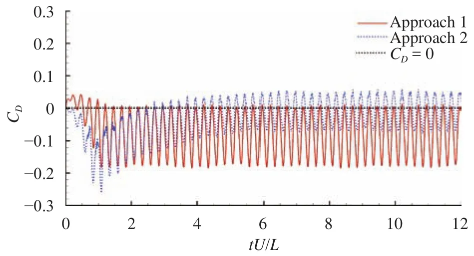
Fig. 4. Time evolutions of the drag force coefficients on the wavy foil solved using both Approach 1 and Approach 2.
Time evolutions of the fish movement and the swimming velocity in the four tail flapping amplitudes are plotted in Fig. 9. As the flapping amplitude is increased, the terminal velocity also increases. But the incasement reduces in a high flapping amplitude. That implies there exists a proper amplitude which is most efficient for the propulsion.
The vorticity contours behind the foil at the time instantare depicted in Fig. 10. With the increase of the amplitudes, the vortex street distributes in a wider region. In each period, the number of vortices shed from the tail is increased. In a higher flapping magnitude, the swimming wake behind the foil tends to be more chaotic.
A typical case regarding the saithe swimming from rest to cruise is simulated using Approach 2 within the-SPH framework. The SPH result will be compared against the numerical result obtained in Ref. [12] and the experimental result obtained in Ref. [24].
The 2D fish body is modeled by the NACA0012 foil as stated before, but the amplitude(see Eq. (1)) in the undulation motion of the foil's centreline is written as [12]

This formula represents a kind of caudal fin propulsion where the lateral displacement of the front part of the body is zero and only the posterior part performs a wavy motion. According to the experimental data [24], the fish length is0.37 m, the cycle of undulations, the wavelength, the phase speedm/s, the maximum wavy amplitude. The density of fluid and the fish body are both equal tokg/m3and dynamics viscosityThese parameters lead to a Reynolds number for this problem as R e= ρcpL/μ =5×10⁵[12].
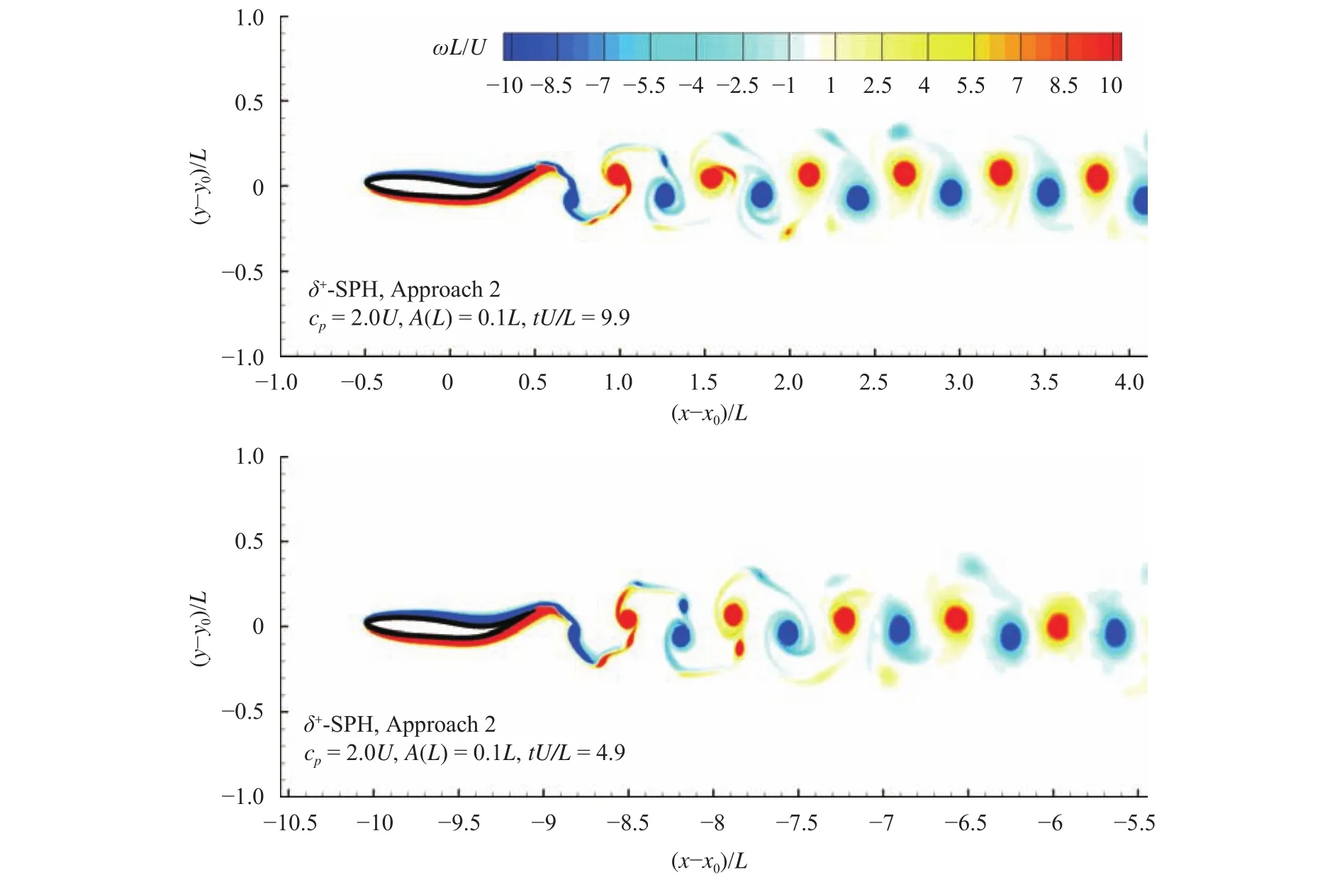
Fig. 5. Vorticity fields behind the wavy foils at the same time instant tU/L = 9.9. Results of Approach 1 and Approach 2 are compared.
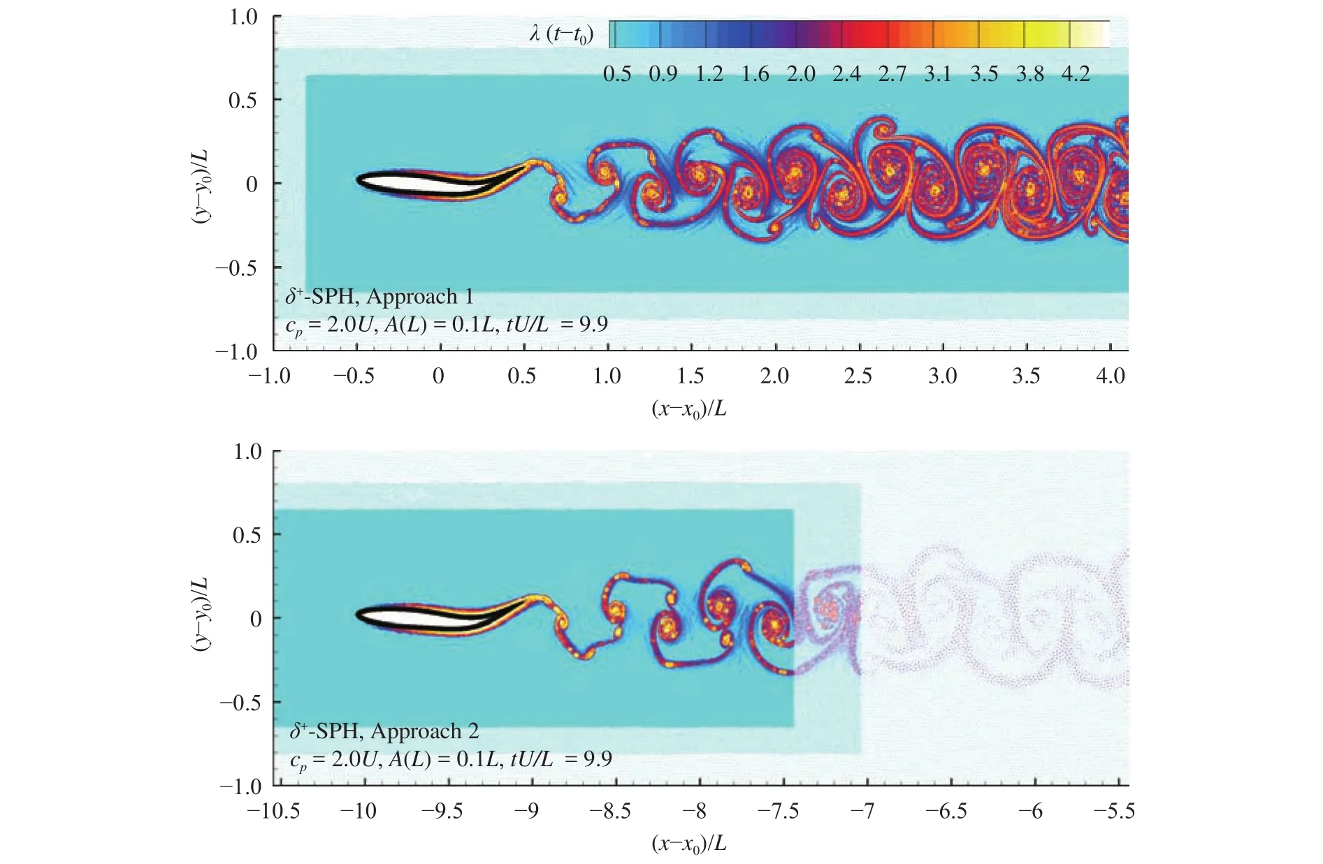
Fig. 6. Lagrangian coherent structures behind the wavy foils at the same time instant tU/L = 9.9. Results of Approach 1 and Approach 2 are compared.
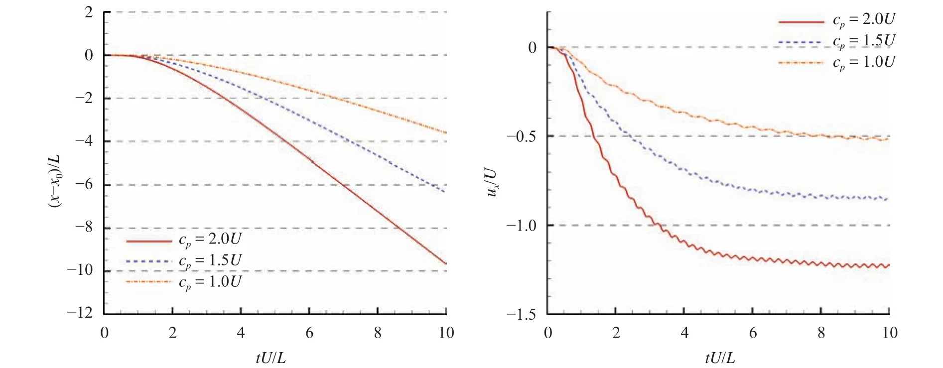
Fig. 7. Time evolutions of the fish movement and the swimming velocity of the fishlike swimming foil with three different phase speeds in Approach 2.
The streamwise and transverse motions on the center of mass of the fish are both allowed in this case. Time evolutions of the swimming velocity in forward and lateral directions are plotted in Fig. 11. After a transitional stage, the swimming velocity of the fish reaches a steady state, i.e. the cruising velocity. The cruising velocity predicted by the SPH model is aboutwhich is closer to the experimental valuethan the numerical resultas predicted by the FVM method [12]. The vortical structures shed behind the foil is depicted in Fig. 12. In this case, the Reynolds number is much higher than the cases and therefore the sizes of the vortices are smaller and their distribution is more chaotic.
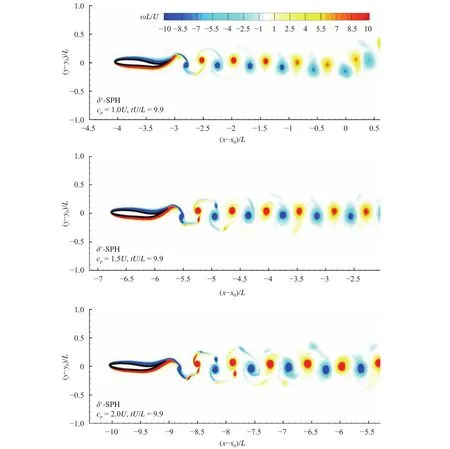
Fig. 8. Vorticity contours behind the fishlike swimming foil at for three different phase speeds,, andin Approach 2.
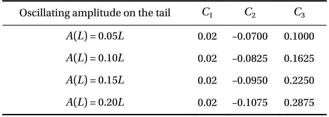
Table 1 Parameters for the determination of oscillating amplitudes on the tail of the wavy foil.
In the present work, fishlike swimming problems are modeled using a particle method. It is demonstrated that the recently developedscheme is very suitable in solving this kind of problem. The problems of high computational costs and tensile numerical instability are avoided inscheme since APR and TIC have been implemented.
The fish-swimming motion can be well modeled within the framework of the particle method. The fish body undergoes large deformations and it can swim to anywhere in the flow field,avoiding the problem of mesh distortion or re-mesh in meshbased methods. Two investigation approaches are adopted for this topic. It shows that within SPH method, both of the two investigation approaches can be realized conveniently. But for a self-propulsive problem, the result by Approach 2 seems to be closer to the real status of the fish swimming. The accuracy of the SPH results are validated by comparing with other numerical results or experimental data in the literature.
Thanks to the Lagrangian nature of SPH method, LCSs can be conveniently detected through the calculation of FTLE field and help to provide a Lagrangian way in visualizing the vortical structures and understanding the flow physics.
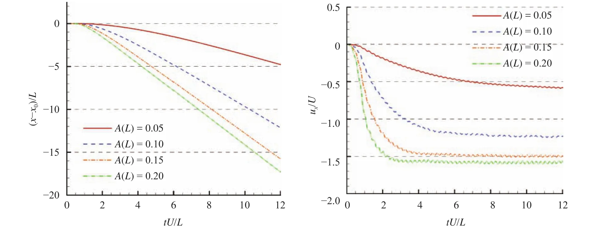
Fig. 9. Time evolutions of the fish movement and the swimming velocity of the fishlike swimming foil with four different oscillating amplitudes on the fish tail.
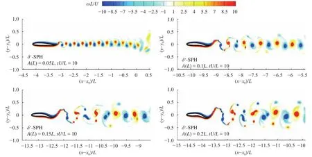
Fig. 10. Vorticity contours behind the fishlike swimming foil at for four different oscillating amplitudes on the fish tail.
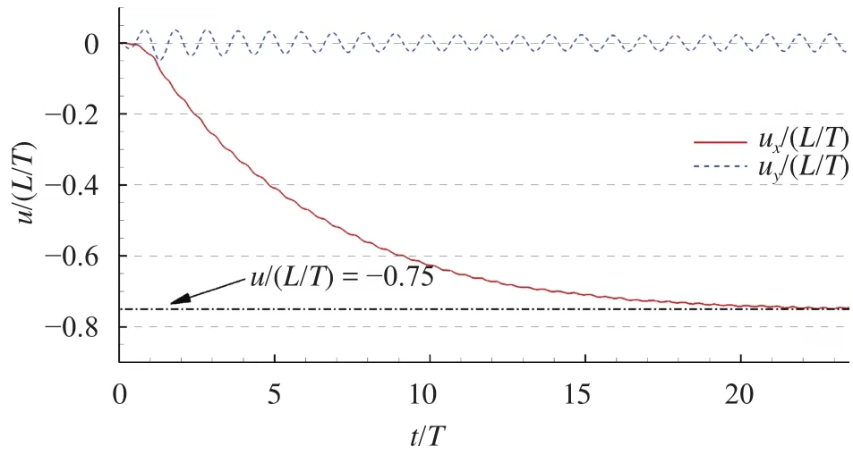
Fig. 11. Modeling of a saithe swimming from rest to cruise: time evolutions of the swimming velocity in forward and lateral directions.
In the future studies, the presentscheme is straightforward to be extended in the fishlike swimming problems in 3D.Complex interactions among more than two fishes in different positions can be investigated, in order to further explain the mechanism of fish schooling in nature. In addition, since SPH is very good at modelling free-surface flows, the study of the interaction between fish and free-surface can also be carried out.
Acknowledgements
This work was funded by the National Natural Science Foundation of China (U1430236) and the PhD Student Research and Innovation Fund of the Fundamental Research Funds for the Central Universities (HEUGIP201701), to which the authors are most grateful.

Fig. 12. Modeling of a saithe swimming from rest to cruise: the vorticity contour behind the swimming saithe at t/T = 23.
References
[1]F.E. Fish, G.V. Lauder, Passive and active flow control by swimming fishes and mammals, Annu. Rev. Fluid Mech. 38 (2006)193–224.
[2]M.J. Lighthill, Hydromechanics of aquatic animal propulsion,Annu. Rev. Fluid Mech. 1 (1969) 413–446.
[3]M.S. Triantafyllou, G.S. Triantafyllou, D.K.P. Yue, Hydrodynamics of fishlike swimming, Annu. Rev. Fluid Mech. 32 (2000)33–53.
[4]Y. Yang, B.G. Tong, A numerical study on a simplified tail model for turning fish in C-start, J. Hydrodyn. Ser. B 18 (2006)135–142.
[5]R. Godoy-Diana, J.L. Aider, J.E. Wesfreid, Transitions in the wake of a flapping foil, Phys. Rev. E 77 (2008) 016308.
[6]J. Deng, X.M. Shao, A.L. Ren, Numerical study on propulsive performance of fish-like swimming foils, J. Hydrodyn. Ser. B 18(2006) 681–687.
[7]W.X. Huang, S.J. Shin, H.J. Sung, Simulation of flexible filaments in a uniform flow by the immersed boundary method, J.Comput. Phys. 226 (2007) 2206–2228.
[8]S.Z. Wang, G.W. He, X. Zhang, Self-propulsion of flapping bodies in viscous fluids: Recent advances and perspectives, Acta Mech. Sin. 32 (2016) 980–990.
[9]J. Deng, X.M. Shao, Z.S. Yu, Hydrodynamic studies on two traveling wavy foils in tandem arrangement, Phys. Fluids 19 (2007)113104.
[10]G.J. Dong, X.Y. Lu, Characteristics of flow over traveling wavy foils in a side-by-side arrangement, Phys. Fluids 19 (2007)057107.
[11]S.Z. Wang, B.J. Shi, Y.H. Li, et al., A large eddy simulation of flows around an underwater vehicle model using an immersed boundary method, Theor. Appl. Mech. Lett. 6 (2016) 302–305.
[12]Y. Yang, G.H. Wu, Y.L. Yu, et al., Two-Dimensional Self-Propelled Fish Motion in Medium: An Integrated Method for Deforming Body Dynamics and Unsteady Fluid Dynamics,Chinese Phys. Lett. 25 (2008) 597–600.
[13]A. Gilmanov, F. Sotiropoulos, A hybrid Cartesian/immersed boundary method for simulating flows with 3D, geometrically complex, moving bodies, J. Comput. Phys. 207 (2005) 457–492.
[14]J.J. Monaghan, Smoothed particle hydrodynamics, Annual Review of Astronomy and Astrophysics 30 (1992) 543–574.
[15]A. Colagrossi, M. Landrini, Numerical Simulation of Interfacial Flows by Smoothed Particle Hydrodynamics, J. Comput. Phys.191 (2003) 448–475.
[16]A.M. Zhang, P.N. Sun, F.R. Ming, et al., Smoothed particle hydrodynamics and its applications in fluid-structure interactions, J. Hydrodyn. Ser. B 29 (2017) 187–216.
[17]J. Carling, T.L. Williams, G. Bowtell, Self-propelled anguilliform swimming: simultaneous solution of the two-dimensional Navier-Stokes equations and Newton's laws of motion, J. Exp.Biol. 201 (1998) 3143–3166.
[18]Z.Q. Xin, C.J. Wu, Numerical simulations and vorticity dynamics of self-propelled swimming of 3D bionic fish, Sci. China Phys. Mech. 55 (2012) 272–283.
[19]Z.Q. Xin, C.J. Wu, Shape optimization of the caudal fin of the three-dimensional self-propelled swimming fish, Adv. Appl.Math. Mech. 56 (2013) 328–339.
[20]P.N. Sun, A. Colagrossi, S. Marrone, et al., Detection of Lagrangian Coherent Structures in the SPH framework, Comput.Methods Appl. Mech. Eng. 305 (2016) 849–868.
[21]G. Haller, Lagrangian coherent structures, Annu. Rev. Fluid Mech. 47 (2015) 137–162.
[22]R. Kumar, J.T. King, M.A. Green, Three-dimensional finite-time Lyapunov exponent field in the wake of an oscillating trapezoidal pitching panel, in: the 47th AIAA Fluid Dynamics Conference, 2017, p. 4420
[23]P.N. Sun, A. Colagrossi, S. Marrone, et al. , Multi-resolution delta-plus-SPH with tensile instability control: Towards high Reynolds number flows, Comput. Phys. Commun. 224 (2018)63–80.
[24]J.J. Videler, Fish Swimming, Springer Science & Business Media, 1993, Vol. 10.
[25]P.N. Sun, A.M. Zhang, S. Marrone, et al., An accurate and efficient SPH modeling of the water entry of circular cylinders, Appl. Ocean Res. 72 (2018) 60–75.
[26]M. Antuono, A. Colagrossi, S. Marrone, et al., Free-surface flows solved by means of SPH schemes with numerical diffusive terms. Comput, Comput. Phys. Commun. 181 (2010) 532–549.
[27]S. Marrone, M. Antuono, A. Colagrossi, et al., δ-SPH model for simulating violent impact flows, Comput. Methods Appl. Mech.Eng. 200 (2011) 1526–1542.
[28]S.J. Lind, R. Xu, P.K. Stansby, et al. , Incompressible smoothed particle hydrodynamics for free-surface flows: A generalised diffusion-based algorithm for stability and validations for impulsive flows and propagating waves, J. Comput. Phys. 231(2012) 1499–1523.
[29]D. A. Barcarolo, D. le Touzéand, G. Oger, et al., Adaptive particle refinement and derefinement applied to the smoothed particle hydrodynamics method, J. Comput. Phys. 273 (2014)640–657.
[30]L. Chiron, G. Oger, M. de Leffe, et al., Analysis and improvements of Adaptive Particle Refinement (APR) through CPU time, accuracy and robustness considerations, J. Comput. Phys.354 (2018) 552–575.
[31]P.N. Sun, F.R. Ming, A.M. Zhang, Numerical simulation of interactions between free surface and rigid body using a robust SPH method, Ocean Eng. 98 (2015) 32–49.
[32]I. Federico, S. Marrone, A. Colagrossi, et al., Simulating 2D open-channel flows through an SPH model, Eur. J. Mech. BFluid 34 (2012) 35–46.
[33]A. Colagrossi, B. Bouscasse, M. Antuono, et al., Particle packing algorithm for SPH schemes, Comput. Phys. Commun. 183(2012) 1641–1653.
[34]S. Marrone, A. Colagrossi, M. Antuonoand, et al., A 2D+t SPH model to study the breaking wave pattern generated by fast ships, J. Fluids Struct. 27 (2011) 1199–1215.
[35]Adami, S and Hu, X., A generalized wall boundary condition for smoothed particle hydrodynamics, J. Comput. Phys 231 (2012)7057–7075.
[36]G. Fourey, C. Hermange, D. Le Touzé, et al., An efficient FSI coupling strategy between Smoothed Particle Hydrodynamics and Finite Element methods, Comput. Phys. Commun. 217(2017) 66–81.
[37]B. Bouscasse, A. Colagrossi, S. Marrone, et al., Nonlinear water wave interaction with floating bodies in {SPH}, J. Fluids Struct.42 (2013) 112–129.
[38]P.N. Sun, A. Colagrossi, S. Marroneand, et al., Theplus-SPH model: Simple procedures for a further improvement of the SPH scheme, Comput. Methods Appl. Mech. Eng. 315 (2017)25–49.
杂志排行
Theoretical & Applied Mechanics Letters的其它文章
- Graphical Abstract
- Sound absorption characteristic of micro-helix metamaterial by 3D printing
- An analysis of dynamic stability of an elastic column
- Local buckling of thin plate on tensionless elastic foundations under interactive uniaxial compression and shear
- Quantitative characterization of deformation and damage process by digital volume correlation: A review
- Forced vibration analysis of nano-composite rotating pressurized microbeam reinforced by CNTs based on MCST with temperature-variable material properties
