A new equivalent method to obtain the stoichiometric fuel-air cloud from the inhomogeneous cloud based on FLACS-dispersion
2018-05-19YulongZhangYuxinCaoLizhiRenXueshengLiu
Yulong Zhang*, Yuxin Cao, Lizhi Ren, Xuesheng Liu
PowerChina railway construction Co., LTD, Beijing,100044,China
With the application of quantity risk analysis to the 18thsubway line of Chengdu, China, FLACS code, as a computational fluid dynamics (CFD) tool, plays a key role. It embedded Q4, Q5,Q8 and Q9 as the models for equivalent fuel-air cloud volume.The benefit of the equivalent approaches is ease to get a representative distribution of explosion loads with minimum number of simulations.
In these models, the laminar burning velocity and volume expansion ratio are taken into account in the Q5 and Q9 methods, only the laminar burning velocity is taken into account in Q4, the volume expansion ratio is only taken into account in the Q8 method. Detailed information about them can be found in literature[1].
Q9, as the latest version, is widely used to assess the explosion loads as part of a risk or consequence analysis [2], and is described by Eq. (1) in FLACS:

where ER is equivalence ratio,(F/O is the ratio of fuel and oxygen); Viis the ithcontrol volume of the numerical grid inside the fuel-air region where the fuel-air is in the range of lower flammability limit (LFL) and the upper flammability limit(UFL), that is ERLFL≤ER≤ERUFL;is volume expansion ratio at constant pressure in the ithcontrol volume, its value depend on the ERi;is shown with Eq. (2):

where SLis the laminar burning velocity.
In Eqs. (1) and (2), the volume expansion ratio and laminar burning velocity are the two key factors for representing the inhomogeneous fuel-air cloud as a homogeneous fuel-air cloud in Q9 model.
The factor, volume expansion ratio, employed in Q9 denotes that the part of ignitable heated fuel-air is expelled out of the control volume in explosion process because the Q9 can be got in the dispersion simulation stage prior to explosion simulation stage, thus, the donation of the expelled fuel-air to explosion load is ignored and its effect may be underestimated. However,in most realistic cases, the computing domain will not be completely filled with an ignitable fuel-air cloud, the deemed expelled fuel-air is still in the computing domain and also plays an important role in the explosion process, its donation on the explosion load cannot be neglected. It seems inappropriate that the volume expansion ratio is introduced into the equivalent approaching.
On the other hand, Q9 only employs SLwith first order to describe the combustion process. Most of the realistic fuel-air explosion process, the fuel-air flow field turns into turbulent regime and the flame propagation is also in violent and turbulent status.
To give a more reasonable equivalent fuel-air cloud size, a turbulent burning velocity STis proposed. Many models, such as Zimont correlation, Peters Correlation and Mueller correlation[3], describe STas a function of SLand turbulence quantities. So, it is also reasonable to describe STas the SLwith a non-one order based on TNO (abbreviation for the Netherlands Organization) multi-energy method (ME).
In the multi-energy method, an idealized fuel-air explosion scenario model is put forward, shown in Fig. 1. The explosion is based on a ground-level hemispherical fuel-air cloud which is filled with a fuel-air mixture at a stoichiometric concentration.
Figure 1 shows the main features of an idealized explosion scenario, a ground-level hemispherical fuel-air cloud is ignited in the center, the flame front will then propagate symmetrically from the centre. the initial peak overpressure in the hemispherical fuel-air cloud zone is assumed as a constant P0whereas the side-on overpressure and dynamic pressure will decay with distance outside of the fuel-air zone.
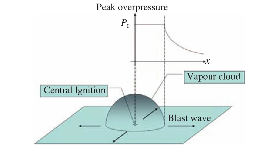
Fig. 1. Idealized fuel-air cloud explosion scenario model.
The peak overpressure calculations in the fuel-air cloud zone are given with the Eqs. (3) and (4). Equation (3) shows the 2 dimensional (2D) explosion expansion, and Eq. (4) shows 3 dimensional (3D) explosion expansion.
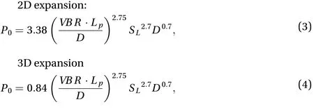
where P0is the peak overpressure; VBR is the volume blockage ratio of the obstructed region; Lpis the maximum flame path length; D is the typical diameter of the obstacles.

where Vgris the obstructed cloud volume in an obstructed region.
Detailed descriptions of the multi-energy method and the calculation of other variables in Eqs.(3) and (4) are found in the literatures [4-11].
It is practicable to assess the peak overpressure of a fuel-air mixture with any concentration by the introduction of stoichiometric concentration. that is, a certain concentration fuelair mixture can be assumed as a kind of new pure flammable gas with a new SL1when the flammable gas’s ER value equals 1.0, the new flammable gas is called pseudo-component gas in literature [6, 12]. As Eq.(3) or Eq.(4) indicate the different peak overpressure value between stoichiometric fuel-air cloud and the other concentration fuel-air cloud depends only onif the other variables remain unchanged (that means the same obstructed region, the same ignition location and the same ignition energy), notably,also indicates that turbulent burning plays a key role during an explosion.
The new approach is trying to transform an inhomogeneous fuel-air cloud into a smaller stoichiometric fuel-air cloud where the explosion can generate similar peak overpressure as the inhomogeneous cloud.
The inhomogeneous fuel-air cloud gets the overpressure P0,and the stoichiometric fuel-air cloud gets the overpressure P1.Then, by setting P0=P1, the following Eq.(6) can be derived from the Eq. (3) or Eq. (4).
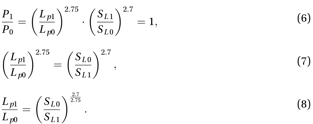
Thus, the following Eq. (9) can be derived by the use of the Eq. (5)


In the view of control volume (CV) from FLACS code, Eq. (12)can be shown as following:

The whole computing domain, which is divided into many control volume using the gridding mechanism, is filled with the different concentration fuel-air cloud (concentration between LFL and UFL). Correspondingly, the homogenous stoichiometric fuel-air cloud volume Vstoiis expressed by the Eq. (13).

The Eq. (13) is the proposed new equivalent cloud method.
A series of simulations are conducted to validate the new equivalent cloud method, For simplifying the representation of the inhomogeneous cloud, 1 m3methane-air clouds with a certain ER value is employed. The obstacles include 61 m-length and 0.2 m-diameter pipes for the representation of blockage.The different ER values and the corresponding laminar burning velocities of methane-air mixtures are shown in Fig. 2, the data source is from the literature [1].
The obstacles and computing domain is shown in Fig. 3. As stated in Fig. 2, the laminar burning velocity curve for methaneair mixture is approximately symmetrical around the axis of ER value at 1.08, the laminar burning velocities where the ER values equals 0.7, 0.8, and 0.9 are selected for the validation simulations, the results from these ER values are the representative results for ER values at 1.37, 1.30 and 1.20 respectively because of the symmetry. When ER equals 1.08 or 1.10, the equivalent stoichiometric clouds volume is approximate same as the original gas clouds respectively, so, they are not selected any more.
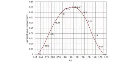
Fig. 2. Laminar burning velocities vs. ER.
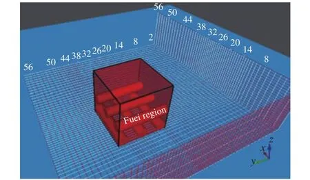
Fig. 3. Obstacles and computing domain.
For comprehensive analysis of the explosion load, three typical cases are taken into consideration, one is the methane-air explosion in open space with obstacles, the other one is the methane-air explosion in open space without obstacles, the last one is the methane-air cloud explosion is in an enclosed space with obstacles [13,14]. The simulating results are shown in Fig. 4.
There is a good agreement by the comparison of the explosion overpressure between equivalent clouds and the cloud which ER equals 0.9 for cases of the cloud explosions in open space. For other scenarios, it seems that there is a poor agreement, in fact, the low peak overpressures indicate the ignited non-stoichiometric clouds are not the explosion process but the combustion process.
For the cloud explosions in the enclosed space, there are good agreements for each ER value respectively. The cloud which ER equals 0.7 can generate the peak overpressure up to 6.561 barg, the corresponding equivalent stoichiometric cloud can generate up to 7.840 barg overpressure, The relative error is within 20%. The relative errors of the other two sets of scenarios are also within 20%.
In this paper, the fuel-air cloud resulting from an accidental discharge event is normally irregular in shape and varying in concentration. Performance of dispersion simulations using CFD-based tool FLACS can get an uneven and irregular cloud.For the performance of gas explosion study with FLACS, the equivalent stoichiometric fuel-air cloud concept is widely applied to get a representative distribution of explosion loads. The Q9 cloud model that is employed in FLACS is an equivalent fuelair cloud representation, in which the laminar burning velocity with first order SLand volume expansion ratio are taken into consideration. However, during an explosion in congested areas,the main part of the combustion involves turbulent flame propagation. Hence, to give a more reasonable equivalent fuelair size, the turbulent burning velocity must be taken into consideration. The paper presents a new equivalent cloud method using the turbulent burning velocity, which is described as a function of SL, deduced from the TNO multi-energy method. To validate the new equivalent cloud method, a series of simulations was conducted. There are good agreements by the comparison of the overpressures between equivalent clouds and the cloud with different ER values if explosion happened.
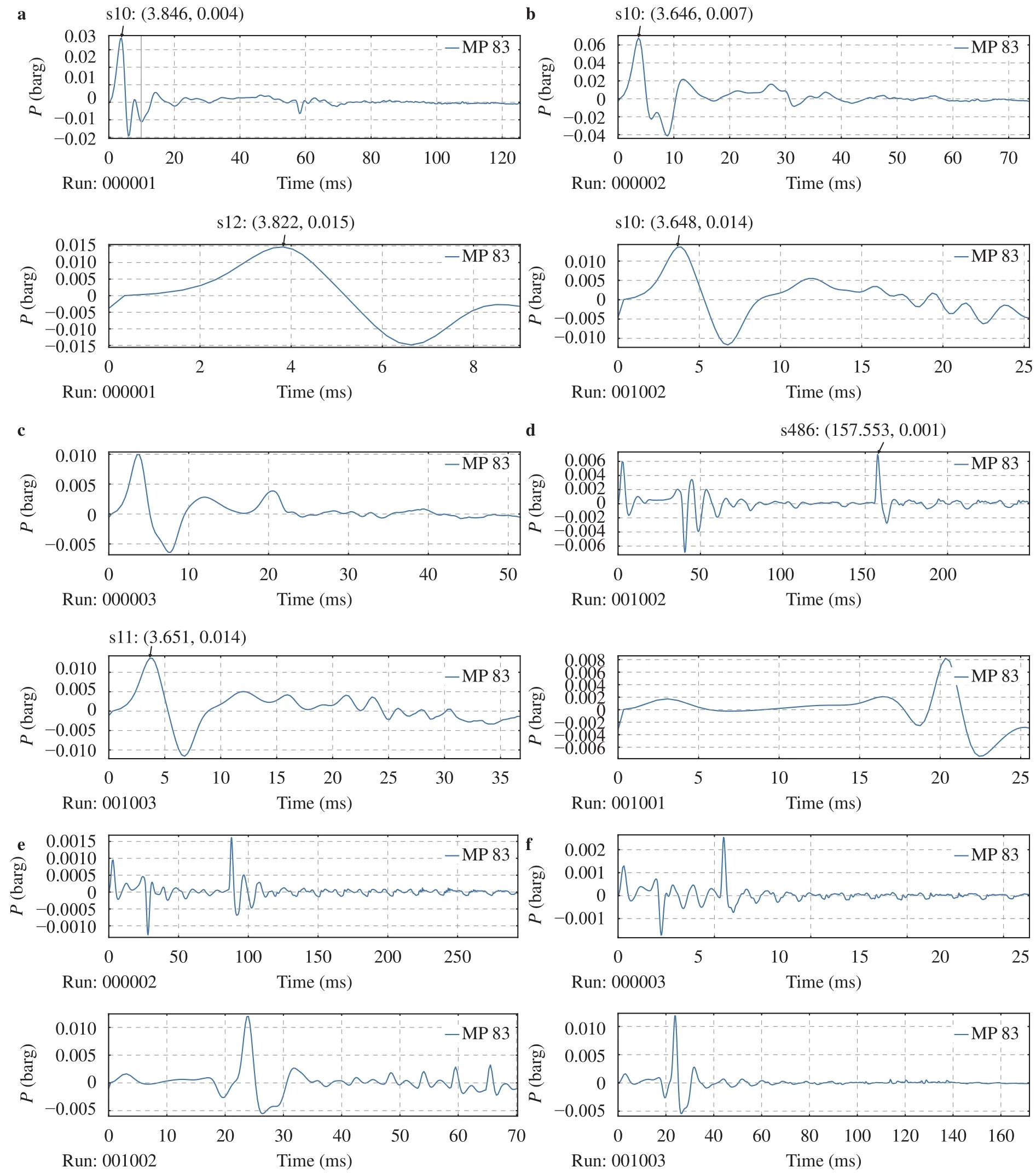
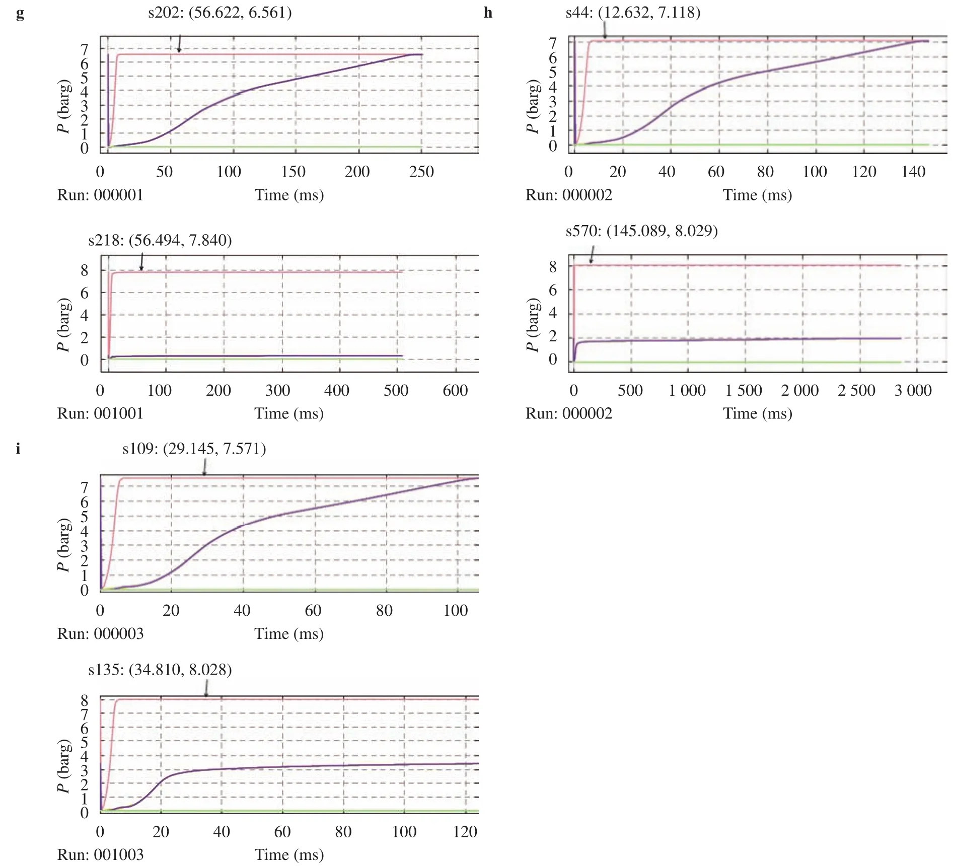
Fig. 4. Explosion of cloud with different ER values and the corresponding equivalent cloud. a ER=0.7 and the corresponding equivalent cloud in open space and obstacles. b ER=0.8 and the corresponding equivalent cloud in open space and obstacles. c ER=0.9 and the corresponding equivalent cloud in open space and obstacles. d ER=0.7 and the corresponding equivalent cloud in open space without obstacles. e ER=0.8 and the corresponding equivalent cloud in open space without obstacles. f ER=0.9 and the corresponding equivalent cloud in open space without obstacles. g ER=0.7 and the corresponding equivalent cloud in enclosed space and obstacles. h ER=0.8 and the corresponding equivalent cloud in enclosed space and obstacles. i ER=0.9 and the corresponding equivalent cloud in enclosed space and obstacles.
Nomenclature
D typical diameter of the obstacles m
ER equivalence ratio -
Lpflame path length m
P0peak overpressure bar
SLlaminar burning velocity m/s
VBR volume blockage ratio -
Vevolume expansion ratio -
Vgrobstructed cloud volume m3
Viithcontrol volume m3
References
[1]A.S. Gexcon, FLACS v10.4 user’s manual, Bergen, 2015
[2]NORSOK Standard Z-013: Risk and emergency preparedness assessment, Norway, 2010
[3]ANSYS Inc., ANSYS CFX-Solver Theory Guide, Pennsylvania,2016
[4]C.J.H. van den Bosch, R.A.P.M. Weterings, Methods for the calculation of physical effects, TNO Prins Maurits Lab., Netherlands, 2005
[5]J.B.M.M. Eggen, GAME: development of guidance for the application of the multi-energy method, TNO Prins Maurits Lab.,Netherlands 1998
[6]DNV Software: UDM theory document, Norway, 2011
[7]W.P.M. Mercx, A.C. van den Berg, D. van Leeuwen, Application of correlations to quantify the source strength of vapour cloud explosions in realistic situations Final report for the project:"GAMES", TNO Prins Maurits Lab., Netherlands 1998
[8]DNV Software, Obstructed region explosion model (OREM)theory, Norway, 2010
[9]A.C. van den Berg, A.L. Mos, Research to improve guidance on separation distance for the multi-energy method (RIGOS), TNO Prins Maurits Lab., Netherlands 2005
[10]W. Zhang, D. Lu, J. Wang, Comparison of Vapor Cloud Explosion (VCE) Consequences Prediction Models, Industrial Safety and Environment Protection, 36 (2010) 48–52. (in Chinese)
[11]G. Fitzgerald, A Comparison of Simple Vapor Cloud Explosion Prediction Methodologies, Second Annual Symposium, Mary Kay O'Connor Process Safety Center "Beyond Regulatory Compliance: Making Safety Second Nature" Reed Arena, Texas A&M University, College Station, Texas, 2001
[12]Z. Wu, S. Hu, Y. Tan, Simplified Calculation of Maximum Blast Pressure of Poly-Ingredient Flammable Mixed Gases, Journal of Combustion Science and Technology 16 (2010) 118–122. (in Chinese)
[13]S. Tian, J. Liu, K. Gao, Experimental study on shock wave impulse and pressure rise rate of gas explosion in airtight pipeline,Journal of Safety Science and Technology, 11 (2015) 17–21. (in Chinese)
[14]E. Vyazmina, S. Jallais, Validation and recommendations for FLACS CFD and engineering approaches to model hydrogen vented explosions Effects of concentration, obstruction vent area and ignition position, Hydrogen Energy, 2016
杂志排行
Theoretical & Applied Mechanics Letters的其它文章
- Graphical Abstract
- Sound absorption characteristic of micro-helix metamaterial by 3D printing
- An analysis of dynamic stability of an elastic column
- Local buckling of thin plate on tensionless elastic foundations under interactive uniaxial compression and shear
- Quantitative characterization of deformation and damage process by digital volume correlation: A review
- Forced vibration analysis of nano-composite rotating pressurized microbeam reinforced by CNTs based on MCST with temperature-variable material properties
