Singularity analysis for single gimbal control moment gyroscope system using space expansion method
2018-04-21SchoolofAstronuticsNnjingUniversityofAeronuticsndAstronuticsNnjing210016Chin
School of Astronutics,Nnjing University of Aeronutics nd Astronutics,Nnjing 210016,Chin
bSchool of Astronautics,Harbin Institute of Technology,Harbin 150001,China
1.Introduction
Single Gimbal Control Moment Gyroscope(SGCMG)is a kind of momentum exchange actuator for spacecraft attitude control,due to its powerful momentum storage capacity and amazing torque amplification ability over Reaction Wheel(RW),magnetic torque,etc.The SGCMG,owing to its efficiency,plays a significant role in attitude control of large spacecraft and agile spacecraft.Larger angle maneuver,multi target acquisition and precise pointing are the major characteristics for the next generation earth observation and imaging satellite.1The World View satellites launched by the Digital Globe and Ball Aerospace and Technologies Corporation could capture High Resolution(HR)images,of which the World View 4 is the most advanced throughout the history.2Launched in 2001 the World View 1 is the first commercial HR imaging satellite equipped with the CMGs,which can only capture the images with 0.5 m panchromatic resolution and 2 m multispectral resolution.While the World View 4 launched on Nov.11,2016 advances a great step and is capable for 0.31 m panchromatic resolution and 2 m multispectral resolution images.
The most serious situation,however,in using CMG is the inherent geometric singularity,in which there is no torque output along a specific direction.3,4Many theories and strategies have been employed to distinguish the singularity problem and to design CMG steering logics.Null motion,5Singular Value Decomposition(SVD),6,7differential geometry and topology,6–8and others are applied for singularity analysis.The Pseudo-Inverse Logic(PIL)and Null motion,although can steer CMG with no torque errors,fail to deal with singularity.While this tough problem can be tackled by the singular robust steering logics with some torque errors added,which actually is a compromise between the preciseness and robustness.The SVD method gives researchers insight into the torque space and gimbal rate space and explain the mechanism of some logics.
A Space Expansion Method(SEM)is proposed in this work to deal with the singularity problem.The SEM would expand the CMG gimbal movement to n dimensional space and achieve a square Jacobian Matrix which will simplify the procedure to find the corresponding gimbal rate for the given torque command.Besides,two different kinds of transformations,Inverse Mapping Transformation(IMT)and Constant Magnitude Transformation(CMT),are introduced to construct an Expanded Jacobian Matrix.Based on SEM,the singularity of the 3-parallel cluster and pyramid cluster is analyzed with a resulted singular gimbal angle sets.What’s more,a hybrid steering strategy is proposed for the parallel CMG cluster and pyramid CMG cluster,which behaves more energy saving and more precise by comparing with the generalized singular robust logic.
The rest of this paper is brief l y outlined as follows:Section 2 summarizes the CMG dynamic model and steering logics.The space expansion method is represented in Section 3 with some illustrative examples.Section 4 argues the singularity problem and compares the space expansion method with other methods.A simple steering logic is represented in Section 5 to illustrate the advantage and potential of SEM with some simulations.Finally,Section 6 concludes the whole work with some suggestion for future research.
2.CMG dynamics and steering logics
Specific space missions require different CMG con figurations.A cluster with more than 3 CMG units is regarded as redundant configuration,and is qualified for 3 axes attitude control,while the non-redundant system also plays a significant role,which may be expanded to get redundant arrays.The pyramid array is the most studied system9–14and has a mini redundancy.The other non-redundant cluster,3-parallel configuration,is also investigated in this paper due to its simple dynamic mechanism.For the above clusters there exist different steering logics.And their mechanism will be examined and demonstrated by SVD method.
2.1.Parallel and pyramid CMG clusters
Although the non-redundant cluster is not capable for 3-axis attitude control,most agile imaging satellite such as the earth observing satellite only have a larger torque requirement in roll and pitch axes,which inspires scientists to employ 2 or 3 CMGs with the gimbal axis parallels with roll/pitch axis and a RW for yaw axis control.
According to physical mechanism of CMG,the gimbal axis g and the f l ywheel momentum h are orthogonal to each other.Therefore,a gimbal frame{gi,hi,fi}can be derived for theith CMG in a cluster,where f is the unit vector and represents the torque direction.To simplify the dynamic model,all the quantities should be represented in the Spacecraft Reference Frame(SRF).
The 3-parallel cluster structure is shown in Figs.1 and 2 depicts the f l ywheel momentum vectors inX-Yplane.The momentum of the whole system can be written as
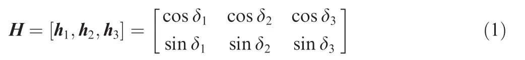
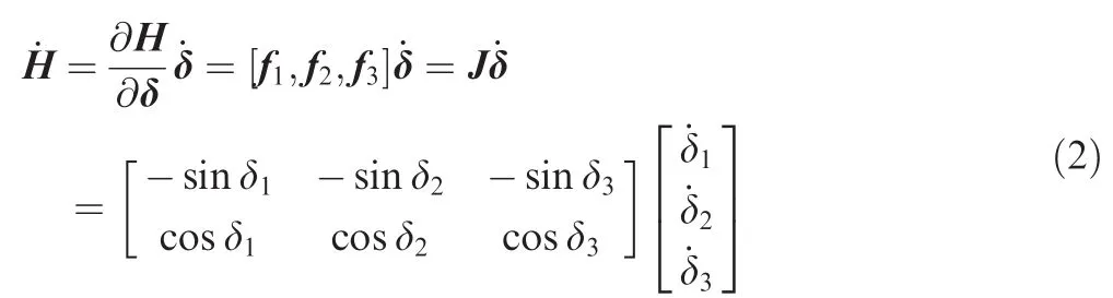
where hiisith CMG f l ywheel momentum represented in the SRF and δiis the corresponding gimbal angle.We suppose that each CMG f l ywheel momentum is 1 in terms of magnitude.Applying differential to Eq.(1)we could get the torque equation
The most classical 4-CMG system is the pyramid configuration,as illustrated in Fig.3.The gimbal axes are normal to the four side faces of a pyramid respectively.Similarly,we could get the momentum as well as the torque equation of the pyramid cluster,and they are given in the following Eqs.(3)and(4).
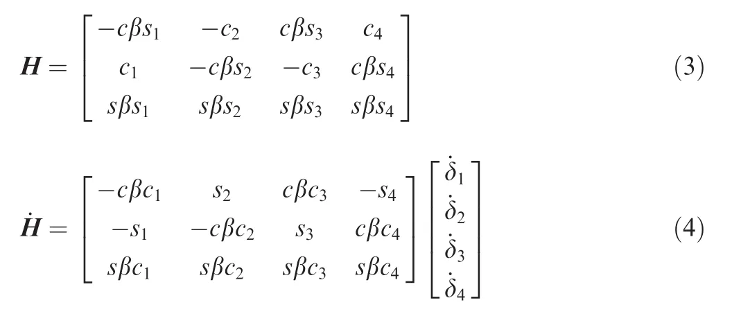

Fig.1 3-parallel CMG cluster.

Fig.2 3-parallel CMG momentum movement.

Fig.3 Pyramid CMG cluster.
where β is the skew angle which are commonly set as 54.73°,60°,or90°,andcβ =cosβ,sβ =sinβ,si=sinδi,and ci=cosδi.
2.2.CMG steering logics
The so-called steering logic is to decide the gimbal rate vector of a CMG cluster for the given control torque command.Because the Jacobian matrix is not a square matrix,we may not find the inverse solution.However,for anm-CMG system,the following optimal problem can be considered

where Q=QTis a weighted matrix and τ is the torque command.The optimal process indeed is to find the weighted minimum two norm solution.Using the Lagrange multiplier method,we can get the solution as
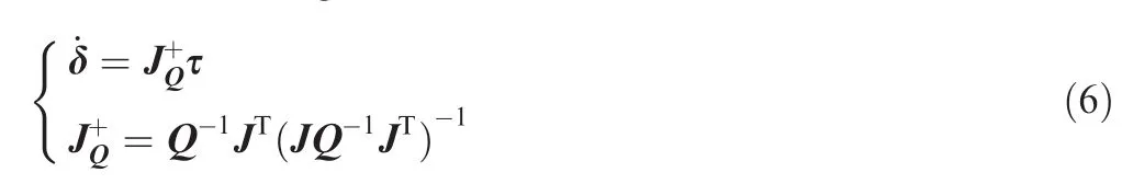
Once Q=I,Eq.(6)would be degenerated to the widely used pseudo-inverse steering logic.
The SVD indicates that a Jacobian Matrix of orderm×ncan be decomposed as

where UTU=Im×mand VVT=In×nis orthonormal matrices.What’s more,S can be expressed in the block matrix form Sm×n= [diag(σ1,σ2,...,σm),0],where σiis the singular value of matrix J.And,the Jacobian matrix can be rewritten as
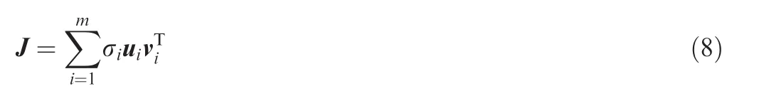
where uiand viis the column vector of U and V respectively.
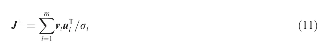
The pseudo-inverse steering logic can also be decomposed into the following form

where S+is of ordern×mand expressed in the block matrix form is
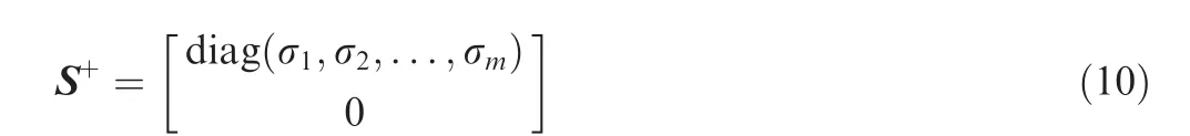
And similarly we have
For a matrix J3×n,the SVD implies that{u1,u2,u3}is a set of basis vector in Ref.6 and for any three dimensional torque command we have
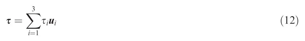
And the gimbal rate by using the pseudo-inverse logic is
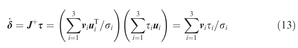
Substituting Eq.(13)into torque equation,the output torque can be written as
Eq.(14)implies that there is no theoretic error by using pseudo-inverse logic.Both the toque and the gimbal rate are linear combinations of uiand virespectively,implying U and V are the torque space and gimbal rate space.Once the CMG system is singular,σ3=0 and there is no torque output along the direction of u3.In this situation,the singularity cannot be escaped or avoided.
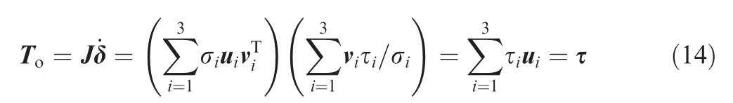
The advisable strategy is to add some error in the steering logic to guarantee the singularity escape,which is a compromise between the robustness and preciseness.Refs.15,16 argued that the agility was much more important than the pointing accuracy in the larger angle maneuver.When considering the following problem,the Generalized Singular Robust Logic(GSRL)can be derived16,17:

where e=τ-J˙δ is the torque error.And the corresponding solution is
where W=P-1and V=Q-1are the weighted matrices and should be properly chosen.The GSRL is able to overcome all kinds of singularity,including elliptic singularity.
3.Space expansion method
The above discussion indicates that a non-square matrix always exists for a cluster consisting of more than 3 CMG units,resulting a troublesome issue to find the inverse solution and overcome the singularities.Here,a Space Expansion Method is introduced to expand the Jacobian Matrix into anndimensional space by applying two different transformations.It is hard to image the transformation of a 3-dimensional vector to n-dimensional space.An illustrative example is presented to help to acquire a better understanding.
Considering an arbitrary vector of order 3,for instance,Fig.4 shows the orthographic projection relationship,where apis the projection vector of a into XY plane and angle α is the projection angle.
Therefore,how could we get the original vector for a given vector(projection vector),and how could we utilize the inverse mapping relationship to expand the space?According to the mapping of 3-to-2 in Fig.5,we could extend the relationship ton-dimensional space,thenn-1 dimensional space is the projection of thendimensional space and viceversa consequently.
One can determine a vector uniquely for a given direction and magnitude,which characterizes the vector sufficiently and necessarily.Similarly,the way to figure out the vector a would be categorized into two types.
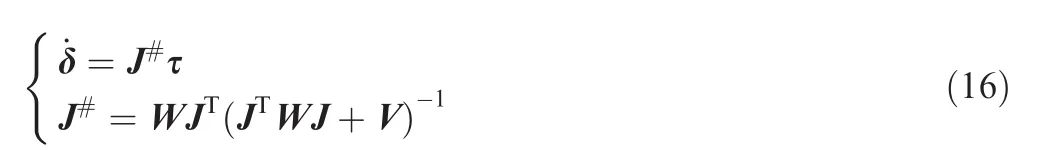
definition 1.The IMT is the inverse process of orthographic projection relationship of the vector.For a given vectorapbelonging ton-1 dimensional space,the original vectorasatisfies where α is the projection angle,||x||denotes the normxand a(1,2,...,n-1)is the vector composed by the firstn-1 elements ofa.

Fig.4 Diagram of inverse mapping.
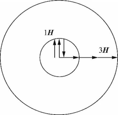
Fig.5 Singularity state of 3-parallel cluster.
Note that the two vectors share the samen-1 components and this relationship would be conserved in both orthographic projection and IMT.From the above definition we can decide the original vector as
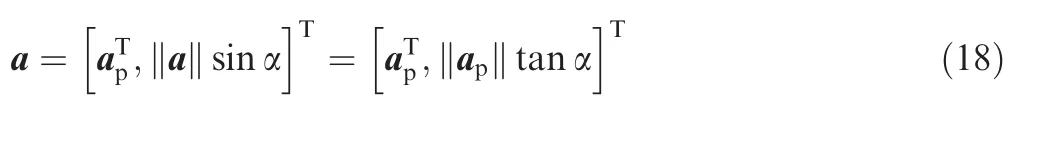
definition 2.The CMT is a kind vector transformation by decomposing an element of projection vectorap(n-1 dimensional)into two to form anndimensional vectoraand||a||=||ap||.
As the name suggests CMT conserves the magnitude of vector apand here the paper proposed the CMT method to obtain the vector a as

The choice of apwill be discussed in Section 4 based on the demanding of free of singularity of Jacobian matrix.The angle α in both two transformations plays a significant role,which during a CMG control process can be modified according to the degree of singularity of the system,rather than a constant value.
The above two transformations have different mechanisms used to characterize and deal with different CMG singularity in the following sections.
4.Singularity analysis using SEM
4.1.Singularity classification
In order to apply the SEM to design steering logic,the CMG singularity will be redefined in this section.Generally,the CMG singularity can be distinguished into 2 parts including elliptic singularity and hyperbolic singularity.Null motion can be used to change the gimbal combination without any torque output and can only treat the hyperbolic singularity.The concept of elliptic or hyperbolic however,seems quite abstract without visual impact.
The SEM is designed to expand the Jacobian matrix Jm×nwhether the original Jacobian Matrix is singular or not.Based on this demand,it is necessary to know what kind of gimbal combination can guarantee full rank after the transformation.Once the system is singular,the rank of Jacobian Matrix will degenerate to 1 for the 3-parallel cluster and 2 for the pyramid cluster,which implies that the row vector of the Jacobian Matrix is no longer linearly independent.
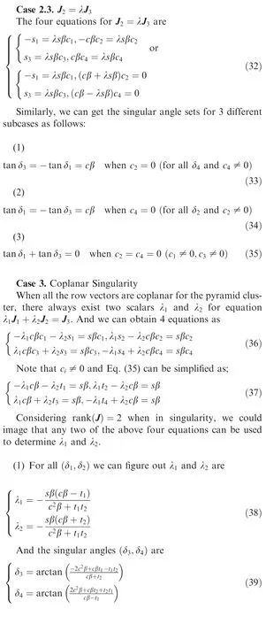
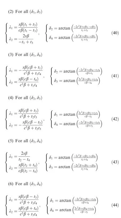
Considering the pyramid CMG cluster,the singular state of the system implies the output of the CMG units are coplanar and the intuitional mathematical relationship is that Jacobian matrix is no longer full rank.Consequently,the relationship the among the row vectors of Jacobian matrix depicts the state of the CMG system.
definition 3.The pyramid CMG system traps into a singularity,only when the row vectors of Jacobian matrix cannot span a three-dimensional torque space corresponding to the degeneration of the rank of Jacobian matrix to 2.
The mathematical expression of definition 3 for a singular CMG system can be written as

where Jiis the row vector of Jacobian matrix lying in a plane and λiis undetermined coefficient.
More specifically,the singularity according to the row vector relation can be categorizes into 2 main parts,zero,parallel and coplanar singularity.The exact formulations are

The physical meaning of the above definitions cannot be more obvious.For a three parallel CMG system,there’s no coplanar singularity apparently.
4.2.Singularity analysis
For a 3-parallel CMG cluster,the singular momentum surface can be depicted by Fig.5 by using the singularity visualization method in Refs.10,18.Beside the two different singular lines 1H(internal)and 3H(external),Fig.5 also shows the rank of the corresponding Jacobian Matrix is 1,which corresponds to the three parallel f l ywheel momentum vectors when the 3-parallel system is singular.
Once one of the row vectors becomes a zero vector,the system traps into zero singularity and no transformation can guarantee full rank of the Expanded Jacobian Matrix.The parallel singularity only emerges when at least two row vectors are parallel to each other.Considering a more general case,the row vector for pyramid cluster is coplanar meaning λ1J1+ λ2J2+ λ3J3=0,and the IMT cannot deal with this coplanar singularity because the relationship cannot be changed.And the following analysis will present the detailed condition of the different singularities and singularity escape.
4.2.1.3-Parallel cluster
The 3-parallel cluster apparently only suffers zero and parallel singularities.
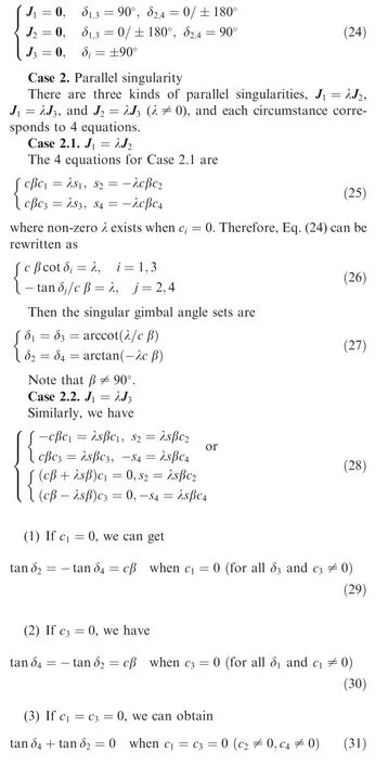
Case 1.Zero singularity
For a 3-parallel cluster,if δi= ±90°, ±180°or 0°,there always exists Ji=0.When the gimbals are δi=0°,we have

Case 2.Parallel singularity
If J1= λJ2(λ ≠ 0),we may obtain the parallel singularity for the 3-parallel cluster,and the angle combinations for this type singularity can be figured out by:

The solution of the above equation is δi=arctan(-λ),which corresponds to different gimbal angle set.For example,if δ = [53.13°,53.13°,233.13°],then λ =-3/4 and we have
Note that there exists no transformations for zero singularity of 3-parallel CMG cluster to form a full rank Jacobian matrix.
4.2.2.Pyramid cluster
The singular problem about 3-parallel is quite simple,while it would be more complex for the pyramid array,which will encounter all kinds of singularities.The following work will distinguish the problem and find the singular angle set.
Case 1.Zero singularity
All of the row vectors are possible to be zero vector with the following gimbal singular angle sets
Case 4.Virtual singularity
The virtual singularity,exactly speaking,is not really a singular state,there may not exist a full rank expanded matrix even for a full rank Jacobian Matrix if the transformation is not properly chosen.If any two gimbal angles are 0°,±90°,or±180°for 3-parallel cluster,there always exist two zero elements in a row vector and any transformation for this row vector cannot get a full rank expanded matrix although the system is still non-singular.For example,when the gimbal angle set of 3-parallel cluster is(0°,0°,53.13°),the system matrix is

Table 1 Gimbal angle set for different singularity.

which is non-singular definitely.When we apply the CMT using the row vector J1to form a new vector J3to expand the matrix to a square matrix,the generated matrix’s rank is still 2 and has no inverse solution.The same situation also exists for pyramid cluster.Table 1 summarizes all the singularity types and gimbal angles according to the corresponding conditions.
The above procedure helps to figure out all the singular gimbal angles,in which each case has the specific geometric interpretation.Wie10obtained the same results using Binet-Cauchy Identity,while the equations in Ref.10had not represented the geometric meaning as in this paper.The procedure is capable for computing singular gimbal angles for all CMG configurations.
4.3.Alpha angle
The major step in using the SEM to deal with the CMG singularity is the proper transformation method and projection angle vector.Once the cluster is no longer singular,the system would be able to behave normally.The singularity classification and analysis above indicate the appropriate choice of transformation for different singularity redefined in the work

Note that no transformation exists to modify the zero singularity,however as illustrated in Table 1,the gimbal angle set for it is quite rare,which means the SEM is able to help escape the almost singularity for 3-parallel and pyramid CMG cluster.
Another critical point is the alpha angle,and there are some rules for the angle determination
(1)Forming a full rank Jacobian Matrix
(2)Varying with the singularity index rather than a constant value
(3)Small size that affect the original system slightly
The above descriptions imply the principle to choose alpha angle,guarantee singularity escape with little influence.
4.4.Comparison with generalized constrained model
Based on the similar thoughts,Refs.18,19discussed the Generalized Constrain Model(GCM)for the single gimbal control moment gyroscope system.It moves the burden of singularity escape from the steering logic design to the CMG dynamics model.By adding constraint conditions to CMG model,the Jacobian Matrix can be expanded to a square matrix,meanwhile the conditions should guarantee the singularity escape.However,there’s no such principles presented to satisfy these conditions.
For a 3-parallel CMG cluster,Refs.18,19advised the constraint as

where
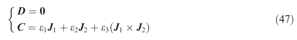
where εiis small scalar.The matrix C is linear independent to J1and J2,however it cannot affect the rank of the expanded matrix JE=[J,C]Tduring singularity,indicating that the singular state cannot be escaped by this kind of model.
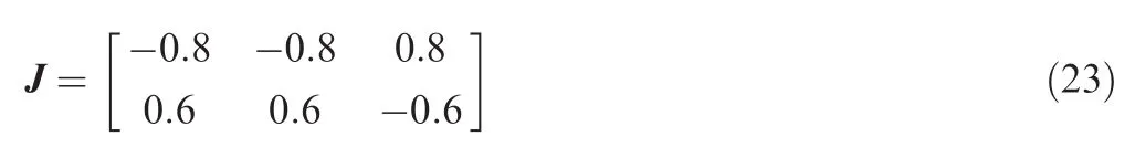
For the Jacobian Matrix in Eq.(23),the GCM form is
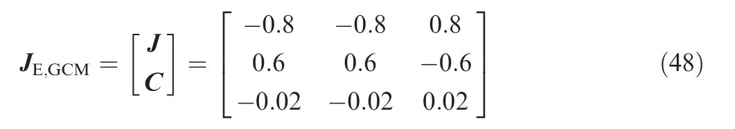
where ε= [0.1,0.1,0.1].What we could find is that the matrix JE,GCMis still singular.While when we use CMT and set the projection angle α = [0.1,0.2,0.15],then the full rank matrix is
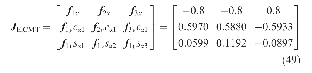
The above transformation does not change the magnitude of the column vector of the Jacobian Matrix,and it’s obvious that IMT cannot escape the parallel singularity because the collinear relationship cannot be disturbed.The mechanism of transformation using the SEM will also be applied to Jacobian Matrix in the following section to calculate the gimbal rate for the torque command.
5.Hybrid steering strategy
A Hybrid Steering Strategy(HSS)will be proposed in this section to demonstrate the advantage of SEM in the singularity escape with MALAB simulations,the results will be compared with the pseudo-inverse logic and GSRL.
5.1.Hybrid steering strategy
The CMG steering logic is to determine the gimbal rate using the equation τ=J˙δ for the given control torque command and most steering logic failing to escape the singularity cannot figure out the gimbal rate in singular state.If one steering logic can set the gimbal rate even in the singular state to track the torque command and the CMG has acceptable dynamic performance,which can be recognized feasible for CMG steering.The HSS proposed in this work emerges from the requirements of singularity escape and calculation simplicity.The CMG Jacobian matrix generally is not a square matrix,and consequently is hard to figure out its inverse solution whether the system is singular state or not.The SEM aims to handle both two problems by forming a full rank square matrix and calculate its invers directly.Once the matrix is full rank,the system is non-singular and is capable for singularity escape.
The hybrid steering strategy is based on the pseudo-inverse logic and SEM.Note that the expanded matrix is a square matrix and the inverse solution can be calculated easily.Therefore,the hybrid steering strategy will combine the inverse and pseudo-inverse solution.The inverse solution is used to change the gimbal angle path or the momentum path to avoid the sin-gularity encountered in the original path using pseudo-inverse logic.
The hybrid steering strategy is
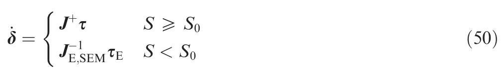
whereS=det(JJT)indicates how serious the system is for the current gimbal angles andS0is the expected threshold value(in following simulationS0=0.5).And τEis the expanded torque from the order of 3 to 4 using the same procedure.
An excellent steering logic can manipulate CMG system under some mathematical techniques even in the singularity.The SEM has been illustrated that it is capable of expanding a Jacobian matrix to a full rank square matrix in most cases,which means the CMG system is controllable.
5.2.Simulations
The 3-parallel cluster and pyramid array are used to examine the performance of the hybrid steering strategy proposed in the previous section.
The parameter for the GSRL is chosen as the same as Ref.18

When considering the gimbal rate constrain,we set

The CMG cluster mostly behaves on the agile spacecraft for large angle maneuver and multi-target acquisition,with the common and effective cascade-saturation control based on the error quaternion feedback.The control method performs like a Bang-Bang control type,by which the spacecraft will experience the accelerate motion,uniform motion and decelerate motion.Correspondingly the control torque has the constant value in accelerate motion phase.The CMG test method advisably is to adopt the simulation to track the constant torque command.
Further,the effective and most used way to test the performance of CMG and steering logic is to set the initial sate of the system in the neighborhood of singularity directly.Among all the singularities,the internal elliptical singularity is the toughest to handle which will be used to choose the initial gimbal angle.If the steering logic is able to calculate the gimbal rate or overcome the elliptical singularity,it can be considered capable of singularity escape.
Based on the above discussion,all of the simulations will be processed with a constant torque command in the neighborhood of a singular state which is serious for CMG system.
Simulation 1:The 3-parallel cluster singularity is to escape from the neighborhood of external singularity,where the initial gimbal angle is chosen as δ0= [4°,4°,10°],‖H0‖ =2.9963 N ·ms andS0=0.0219.And the torque command is (τx,τy)= (-1,0)N ·m.And The projection angle alpha is chosen as α= [1,2,1.2]exp(-10S).The variable alpha angle according to the singularity index indicates that the steering method would transit to pseudo-inverse steering logic smoothly without great steps.

Fig.6 Output torque of 3-parallel cluster by HSS.

Fig.7 Gimbal angles of 3-parallel cluster by HSS.
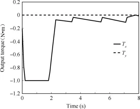
Fig.8 Output torque of 3-parallel cluster by PIL.

Fig.9 Gimbal angles of 3-parallel cluster by PIL.

Fig.10 Output torque of 3-parallel cluster by GSRL.
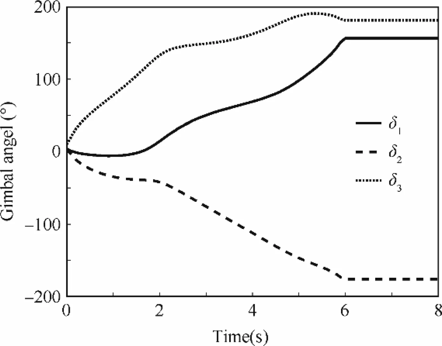
Fig.11 Gimbal angles of 3-parallel cluster by GSRL.
The simulation results are shown in Figs.6-13.The results indicate that HSS has the similar performance with GRSL by comparison of gimbal angle path.Both of them help to escape from the external/saturation singularity and pass the internal/1H singularity two times.And,at t=3 s the system is almost fully de-saturated,however it’s eventually saturated again,which is unavoidable for the constant torque command.Based on the optimal control theory and the proper parameters,GSRL can deal with all kinds of singularities.While the singularity index implies that the system with HSS is always far away from singularity,and performs much better than GSRL because of a much larger value ofS.The expanded Jacobian Matrix is always full rank.The PIL cannot pass through the internal singularity at the timet=2 s and its gimbal rate is saturated as verified in the former section.

Fig.12 CMG momentum of 3-parallel cluster by different logics.
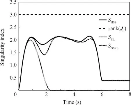
Fig.13 Singularity index of 3-parallel cluster by different logics.

Fig.14 Energy consumption of 3-parallel cluster by different logics.
The HSS is expected to escape the singularity and it performs better than the generalized singular robust logic in this simulation.
Figs.14–16 depict the energy,torque error,and hybrid performance of the three logics during the simulation.Fig.14 is the time history of energy consumption of different steering logics.The energy consumption is defined as the integral of two-norm of gimbal rate).In 0–2 s the three logics almost consume the same energy,however when the system encounters singularity,the hybrid steering strategy consume the minimum energy than GSRL and PIL.Fig.15(Torquer error only exist during the 0–6 s)illustrates the torque errorof the process and the GSRL escapes the singularity with some torque error as designed,and HSS performances much better than GSRL.Fig.16 shows the hybrid performance indexof different logics,from which we can get the same conclusion as above.These analyses verify the advantage of the space expansion method as well as the hybrid steering strategy.
Simulation 2.The initial gimbal angle of the Pyramid cluster(β =54.73°)is chosen near the elliptic singular point δ0= [2,93°,1°,-85°],therefore,it can escape singularity from the neighborhood of internal singularity.ForGSRL,λ =0.01exp(-10S), γi=0.1cost,and Q-1=diag(1,2,3,4)are used. And the torque command is(τx,τy,τz)= (0,0,-0.5)Nm.The corresponding projection angle is α = [1,2,1.2,1.5]exp(-2S).Figs.17–22 show the time history of output torque,gimbal angle,and gimbal rate for three different logics respectively.While the momentum and singularity index are presented in Figs.23 and 24.

Fig.15 Torque error of 3-parallel cluster by different logics.
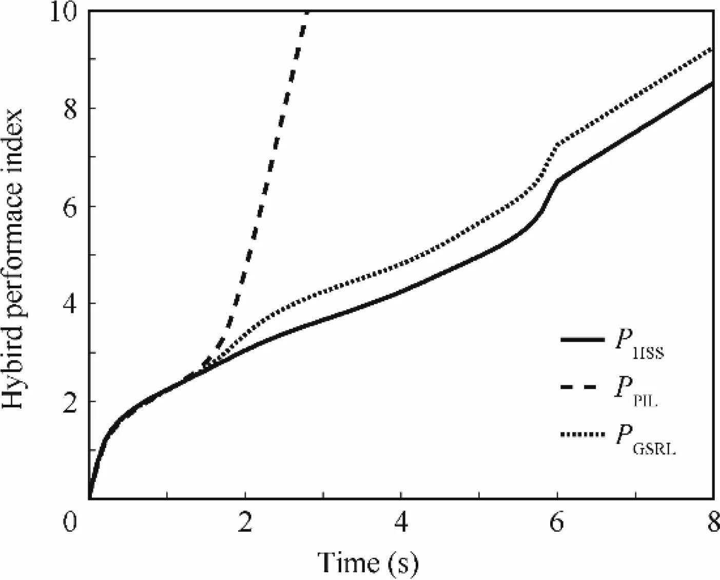
Fig.16 Hybrid performance index of 3-parallel cluster by different logics.

Fig.17 Output torque of pyramid cluster by HSS.
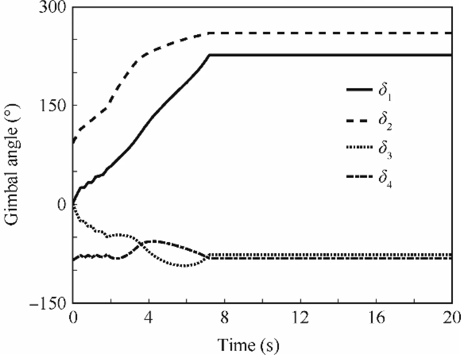
Fig.18 Gimbal angles of pyramid cluster by HSS.

Fig.19 Output torque of pyramid cluster by PIL.
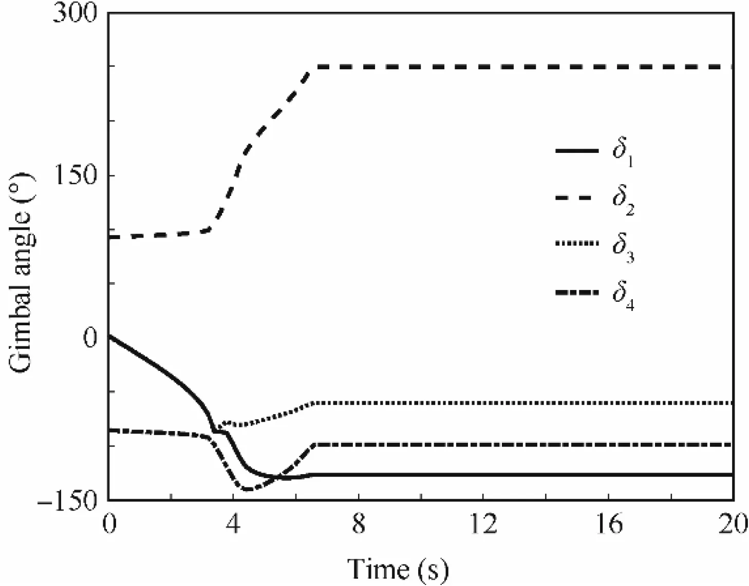
Fig.20 Gimbal angles of pyramid cluster by PIL.
At the neighborhood of an elliptic singular point,HSS results larger gimbal rate,as shown in Fig.23 to escape singularity and change the gimbal angle path.Some errors in the initial phase are unavoidable because HSS is to change the path of the gimbal angle rather than dealing with the singularity directly.After escaping from the singularity,the system performs well to track the command signal until the saturation occurs,as shown in Fig.17.However,the GSRL and PIL steer the system to encounter the singularity again at 4 s,as shown in Fig.24.In order to escape the singularity at 4 s,much more torque errors are added,which even exists in theXandYaxes for GSRL.The reason is that the three systems have different gimbal angle paths(see Figs.18,20,and 22).During the entire process,HSS makes the system have minimum momentum at any time,which indicates the system would work for a long period until saturation,as shown in Fig.24.

Fig.21 Output torque of pyramid cluster by GSRL.
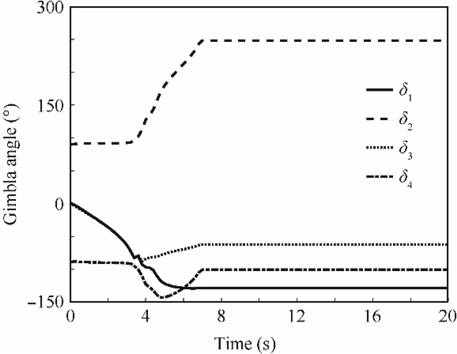
Fig.22 Gimbal angles of pyramid cluster by GSRL.
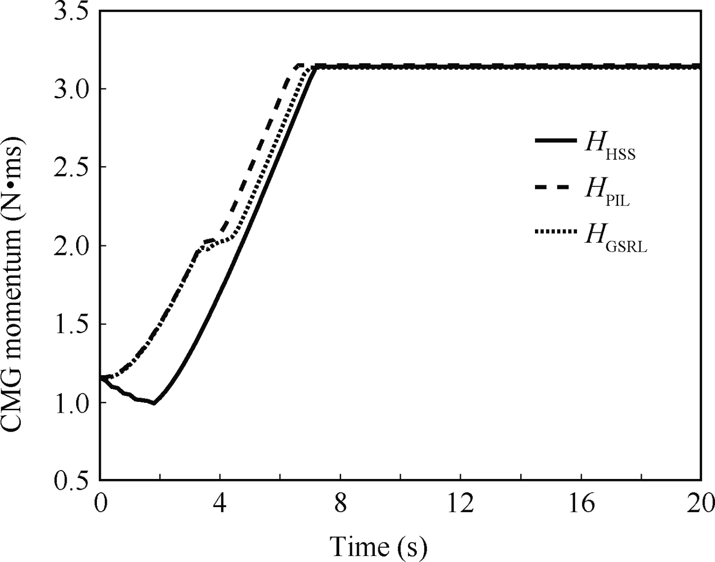
Fig.23 CMG momentum of pyramid cluster by different logics.
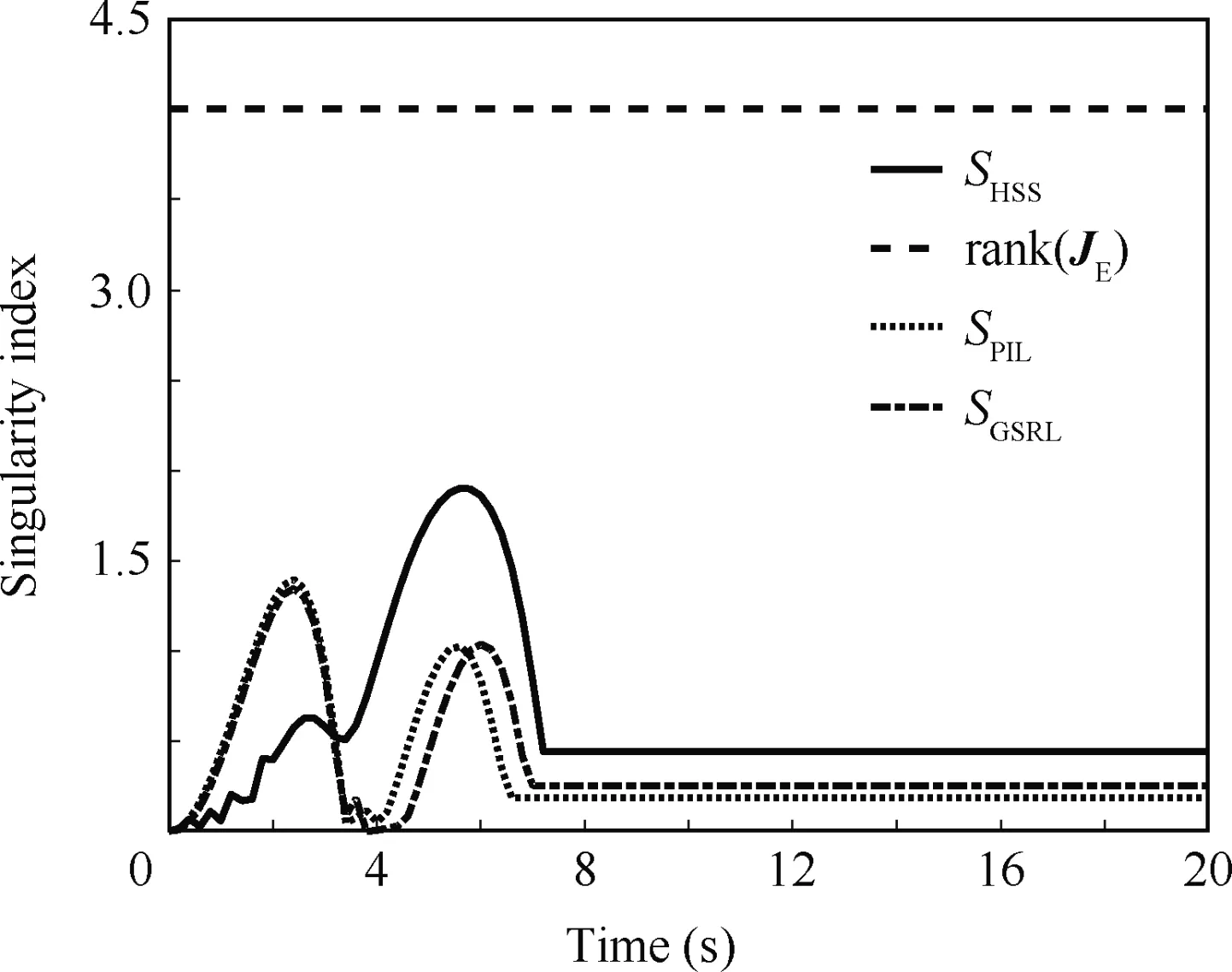
Fig.24 Singularity index of pyramid cluster by different logics.
Simulation 3.In this simulation the spacecraft agile maneuver is adopted equipped with the pyramid cluster.The spacecraft will rotate along its three axes rapid and sever times,and continuously changed control torque command will be processed by the pyramid CMG group to examine the proposed strategy and illustrate the feasibility for spacecraft control.The space craft attitude control is chosen as the quaternion feedback saturation control method1,20,21as
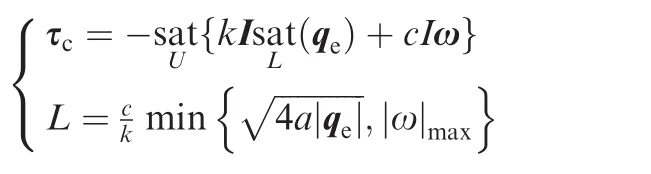
where I is the spacecraft moment of inertia,qe,ω,and a are error quaternion,slew rate,and maximum slew acceleration,kandcare the control gains,andUandLis the output limit.The function sat is the same to Eq.(52).
The control Command is
And the steering strategy is modified as a continuous form,whereAis a kind of switch function asA=1/{1+exp[-μ(S-S0)]}. Here we setA=1/{1+exp[-10(S-0.5)]} and it is obvious thatAis the a switch function changing continuously according to the singularity index to weaken the jitter around the threshold point.The other parameters are shown in Table 2.
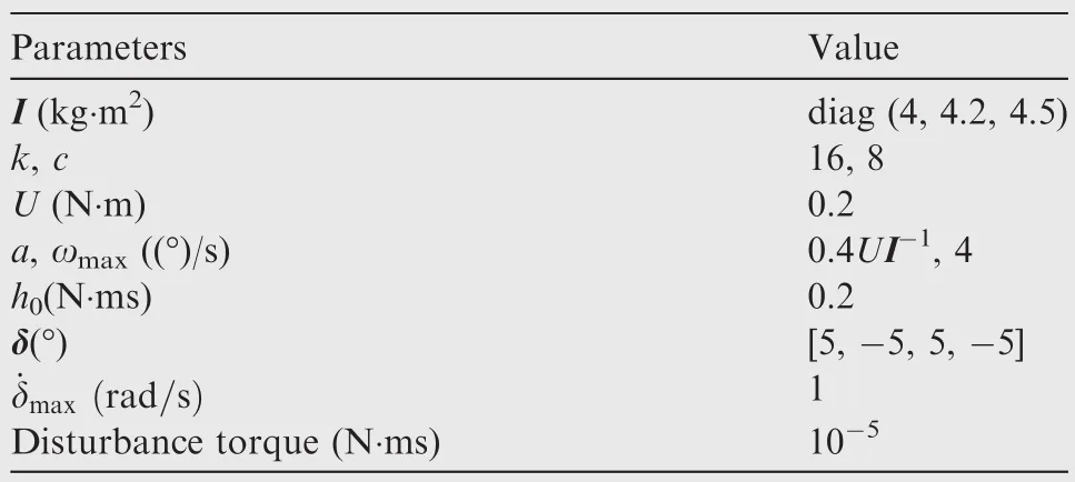
Table 2 Simulation parameters.
As talk above the CMT is able deal with different singularity defined in this paper,and if the rank of the Jacobian matrix is 4,the system is feasible to control with proper angle alpha.Consequently,the alpha can be adjusted by the singularity and here it’s selected as (-0.2,0.3,0.5,2.3)exp(-10S).The simulation result is shown in Figs.25–27.
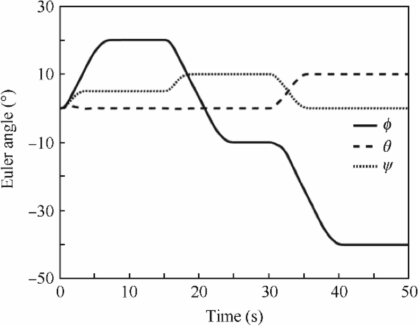
Fig.25 Time history of spacecraft attitude.

Fig.26 Time history of spacecraft slew rate.

Fig.27 Singularity index of the pyramid CMG cluster.
In less than 45 s,the spacecraft maneuvers several times rapidly as illustrated in Fig.25 and the slew rate approaches the limit value 4(°)/s.Obviously the CMG cluster encounters the singularity or is trapped into the neighborhood of the singular state in 0–5 s and 30–35 s,which generates some disturbance on the other axes shown in Fig.26.However,the singularity index indicates the matrix is full rank and nonsingular,meaning the CMG system passes or escapes the singularity rapidly illustrated in Fig.27.The simulations above demonstrated the potential application of SEM for CMG steering logic and spacecraft control.
6.Conclusions
In order to figure out the singularity of CMG system,the space expansion method is proposed in this work with two different vector transformations,including inverse mapping transformation and constant magnitude transformation.Based on the SEM,a new procedure is proposed to figure out the singular gimbal angle sets for the 3-parallel and pyramid clusters.Further,a hybrid steering strategy is designed to change the gimbal path to avoid the singularity.Comparing to the traditional pseudo-inverse logic and the generalized singular robust logic,the steering logic proposed in this paper performs well in terms of energy saving and torque error reducing.In the future study,the SEM should be fully exploited for designing more comprehensive and efficient steering strategy to contribute to the development and application of the agility of the spacecraft.
Acknowledgements
The authors would like to express their acknowledgement for the support from the National Natural Science Foundation of China(No.61403197)and the National Key Research and Development Plan of China(No.2016YFB0500901).
1.Heiberg C,Bailey D,Wie B.Precision spacecraft pointing using single-gimbal control moment gyroscopes with disturbance.J Guid Control Dyn2000;23(1):77–85.
2.DigitalGlobe.The largest constellation in the industry;2017.Available from:https://www.digitalglobe.com/about/our-onstellation[cited 2017 March 27].
3.Hu Q,Guo C,Zhang J.Singularity and steering logic for control moment gyros on flexible space structures.Acta Astronaut2017;137:261–73.
4.Kasai S,Kojima H,Satoh M.Spacecraft attitude maneuver using two single-gimbal control moment gyros.ActaAstronaut2013;84:88–98.
5.Wie B,Bailey D,Heiberg C.Singularity robust steering logic for redundant single-gimbal control moment gyros.J Guid Control Dyn2015;24(5):865–72.
6.Meng T,Matunaga S.modified singular-direction avoidance steering for control moment gyros.J Guid Control Dyn2001;34(6):1915–20.
7.Ford KA,Hall CD.Singular direction avoidance steering for control-moment gyros.J Guid Control Dyn2000;23(4):648–56.
8.Kurokawa H.Survey of theory and steering laws of single-gimbal control moment gyros.J Guid Control Dyn2007;30(5):1331–40.
9.Kurokawa H.A geometric study of single gimbal control moment gyros-singularity and steering law[dissertation].Tokyo:The University of Tokyo;1997.
10.Wie B.Singularity analysis and visualization for single-gimbal control moment gyro systems.J Guid Control Dyn2005;27(5):271–82.
11.Lappas VJ,Steyn WH,Underwood CI.Attitude control for small satellites using control moment gyros.Acta Astronaut2002;51(1):101–11.
12.Sajjad A,Palmer PL,Roberts M.Exact steering law for pyramidtype four control moment gyro systems.AIAA/AAS a strodynamics specialist conference and exhibit.Reston:AIAA;2006.p.1–10.
13.Kurokawa H.Constrained steering law of pyramid-type control moment gyros and ground tests.J Guid Control Dyn1997;20(3):445–9.
14.Yamada K,Asai T,Jikuya I.Inverse kinematics in pyramid-type single-gimbal control moment gyro system.J Guid Control Dyn2016;39(8):1897–907.
15.Wie B.Singularity escape/avoidance steering logic for control moment gyro systems.J Guid Control Dyn2005;28(5):948–56.
16.Wie B.New singularity escape/avoidance steering logic for control moment gyro systems.AIAA guidance,navigation,and control conference and exhibit.Reston:AIAA;2003.p.1–11.
17.Margulies G,Aubrun JN.Geometric theory of single-gimbal control moment gyro systems.J Astronaut Sci1978;27(2):159–91.
18.Laura J,Mason P.A generalized framework for linearly constrained singularity-free control moment gyro steering laws.AIAA guidance,navigation,and control conference.Reston:AIAA;2009.p.1–10.
19.Jones LL,Zeledon RA,Peck MA.Generalized framework for linearly constrained control moment gyro steering.J Guid Control Dyn2012;35(4):1094–103.
20.Wie B.Space vehicle dynamics and control.2nd ed.Reston:AIAA;2008.p.711–4.
21.Wie B,Lu J.Feedback control logic for spacecraft eigenaxis rotations under slew rate and control constraints.J Guid Control Dyn1995;18(6):1372–9.
杂志排行

CHINESE JOURNAL OF AERONAUTICS的其它文章
- Extension of analytical indicial aerodynamics to generic trapezoidal wings in subsonic flow
- Time-varying linear control for tiltrotor aircraft
- Global aerodynamic design optimization based on data dimensionality reduction
- Mesh deformation on 3D complex configurations using multistep radial basis functions interpolation
- Stagnation temperature effect on the conical shock with application for air
- Transient simulation of a differential piston warm gas self-pressurization system for liquid attitude and divert propulsion system