Extension of analytical indicial aerodynamics to generic trapezoidal wings in subsonic flow
2018-04-21AnreDARONCHAntoninoVENTURAMrelloRIGHIMtteoFRANCIOLINIMroBERCIDnielKHARLAMOV
Anre DA RONCH,Antonino VENTURA,Mrello RIGHI,Mtteo FRANCIOLINI,Mro BERCI,Dniel KHARLAMOV
aFaculty of Engineering and the Environment,University of Southampton,Southampton SO17 1BJ,UK
bSchool of Engineering,Zurich University of Applied Sciences,Winterthur 8401,Switzerland
cDipartimento di Ingegneria Industriale e Scienze Matematiche,Universita`Politecnica delle Marche,Ancona I-60100,Italy
dSchool of Mechanical Engineering,University of Leeds,Leeds LS2 9JT,UK
1.Introduction
Indicial theory is a powerful mathematical tool that has been extensively employed in aerodynamics modelling(refer to Ref.1and references therein).Indicial theory asserts that the response of a linear time invariant system to an arbitrary input can be constructed by integrating a linear functional which involves the knowledge of the time dependent input signal and a kernel response.The kernel is an inherent characteristic of the system.Adding a nonlinear dependence of the functional on the input level2extends the capability of the model,allowing a certain class of model nonlinearity to enter the response.It is also important to observe that the traditional Volterra-Wiener theory3,4of nonlinear systems represents a subset of nonlinear indicial theory.
Researchers have followed three paths to address indicial aerodynamic modelling:an analytical path,a numerical path using high-fidelity CFD techniques,and an experimental path using measurements obtained in wind tunnel dynamic tests.
Analytical theories were derived under the assumption of a thin aerofoil in incompressible,irrotational,and twodimensional flow.In the 1920s,Wagner5conducted a series of studies for the unsteady lift generated on an aerofoil due to abrupt changes in the angle of attack.The Wagner function describes the indicial built-up of the circulatory part of the lift,including the influence of the shed wake.Theodorsen6extended those studies by investigating the forces and moments on an oscillating aerofoil.The lift responses of an aerofoil penetrating sharp-edge and harmonically varying gusts were studied by Küssner7and Sears,8respectively.Further details on analytical theories of indicial aerodynamics and some recent developments,including the approach herein proposed,are given in Section 2.
Advances in computational power have allowed significant progress in the use of CFD techniques for modelling of nonlinear unsteady aerodynamics.To overcome the limitations of analytical indicial aerodynamics,restricted to linear flows and thin aerofoils,researchers investigated a few alternatives.The first attempts to directly determine the indicial response by CFD dated back to 1990s.9This approach has received widespread use(see Refs.10,11among many others)but still presents a number of difficulties,mostly associated with the numerical settings of an analysis and the reliability of unsteady results.
Other researchers have approached the modelling problem using indicial aerodynamics derived from wind tunnel dynamic tests and flight test measurements.For example,Refs.12,13applied linear indicial models to data from different testing facilities and different aircraft models.The identification of indicial models from flight test data was documented in Refs.13,14Nonlinear indicial responses were applied to a rolling 65°delta wing,15and in Ref.16to the prediction of a dynamically stalling wing.
A substantial portion of the work described in this paragraph was motivated by the increased manoeuvre capabilities and expanded flight envelopes of modern aircraft.More recently,under the NASA Aviation Safety Program,further research in unsteady modelling has been carried out at NASA Langley Research Center,and an excellent review of these methodologies is presented in Ref.1.
The main contribution of this work is the derivation of an analytical indicial aerodynamics method that extends wellknown theories,which are based on the assumption of thin aerofoils,to generic trapezoidal wings of finite span in subsonic flow.In particular,the paper is built around three objectives.The first is the formulation,application,and demonstration of a consistent analytical framework for predicting unsteady aerodynamic responses to arbitrary changes in the angle of attack and in the vertical component of the free stream speed(gusts).The second objective places emphasis on the use of current state-of-the-art CFD modelling techniques,as provided by a widely-available open-source solver as well as an industrial-grade solver,for predicting unsteady viscous flows.The third objective draws a final assessment of the analytical model predictions considering the CFD-based unsteady aerodynamics uncertainty.A set of trapezoidal wings,with different Aspect Ratios(AR)and sweep angles,is tested at different flow conditions.In total,24 unsteady aerodynamic test cases are executed for each methodology.
The paper continues in Section 2 with the analytical derivation of indicial aerodynamic functions valid for generic trapezoidal wings in subsonic flow.Section 3 summarizes the computational solvers and the appropriate techniques for the calculation of indicial aerodynamics.Then,results for four wing con figurations and a set of flow conditions are presented and discussed in Section 4,highlighting the computational advantages and the related limitations where appropriate.Finally,conclusions are drawn in Section 5.
2.Analytical derivation of indicial functions
Built on previous work,17aerodynamic indicial functions for compressible subsonic flows are herein approximated by modification of the indicial functions for an incompressible flow.Prandtl-Glauert scalability18is used for the circulatory contribution,(τ),and piston theory19for the non-circulatory contribution,(τ).The lift coefficient is then found using the principle of superposition
Analytical formulae are derived combining the work of Queijo et al.20with that of Leishman.21The former describes the wing circulatory lift in incompressible flow,including the wake two-dimensional down wash and the tip vortices three dimensional down wash.22The latter provides a theory for the calculation of the thin aerofoil lift in compressible flow,including Prandtl-Glauert theory for the circulatory terms and piston theory for the non-circulatory terms.
The circulatory lift build-up due to a unit sharp-edge gust with perturbation front parallel to the wing leading edge is then calculated by multiplying the lift response to a step change in the angle of attack with the ratio between Küssner and Wagner functions.23It is worth observing that the latter represents afictitious angle of attack24and approximates the two-dimensional penetration effect within the ‘frozen gust” framework.25
The non-circulatory contribution drives the impulsive-like start of the flow response for any wing shape and is followed by a short yet complex region where outgoing and incoming acoustic waves intersect.19The circulatory contribution drives the subsequent lift build-up until steady state convergence.As the asymptotic lift value provided by Queijo et al.20is originally deemed inaccurate,it is here obtained via simplified lifting-line theory.26An alternative for fine-tuning the asymptotic value is to use available numerical or experimental data27,so that viscous effects may statically be recovered in the absence of significant flow separation.28With identical reference flow conditions,the initial lift coincides for both tuned and untuned cases but later develops with a different rate.
For swept wings,the entry delay relative to each section is geometrically known and considered when obtaining the lift build-up due to a unit sharp-edge gust with perturbation front normal to the reference airflow.
2.1.Analytical derivation of indicial functions
Considering a trapezoidal f l at wing with aspect ratio AR,taper ratio λ and sweep angle Λ,a simplified yet effective parametric model was formulated to calculate the lift build-up due to a unit step in the angle of attack for incompressible flow.20
DenotingMae=MacosΛ the effective Mach number andthe Prandtl-Glauert compressibility factor,
the original analytical model may be extended to compressible subsonic flow in the absence of shock waves,as the(linear)scaling laws break down in the(nonlinear)transonic regime.29The asymptotic steady-state lift coefficient due to a step change in the angle of attack is formulated as:18

where δ is the wing efficiency factor that can be calculated via lifting-line theory26for a straight wing in incompressible flow,or more generally used as a fine-tuning parameter.
The circulatory component of the lift due to a step change in the angle of attack is written as:

whereandare the initial and final values of the circulatory lift coefficient as provided by Queijo et al.20(see Appendix A),whereas=/Eis the actual initial value withEthe complete elliptic integral of the second kind;22thenαcoefficientsandare obtained by best-fitting the entire indicial function for incompressible flow.
For the gust encounter,it is assumed that the ‘frozen gust”approach23is valid and that the gust front is parallel to the wing leading edge.The circulatory lift development due to a sharp-edged gust is written as:
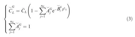
where thenGcoefficientsare obtained by best fitting the indicial lift resulting from multiplying the circulatory lift development due to a unit step in the angle of attack by the ratio between Küssner’s and Wagner’s functions for the case of incompressible flow(see Appendix A),thus accounting for the gust-entry delay.30
For the four wing con figurations of this study(see Fig.1),Table 1 reports the optimal coefficients for approximating the indicial lift function to a step change in the angle of attack in incompressible flow withnα=3 while Table 2 reports those to approximate the response to a sharp-edge gust withnG=4 All coefficients were obtained via constrained nonlinear optimisation31by minimizing the root-mean-square error between the approximate and original curves in Appendix A.

Fig.1 A schematic of the four wing configurations.
2.2.Non-circulatory part
The exact non-circulatory lift contribution is analytically known via piston theory and extends into a complex transitory region where the indicial function presents a change of slope,32which originates from an interaction between outgoing and incoming acoustic waves leaving the aerofoil at=2Mae/(1+Mae)and=2Mae/(1-Mae),respectively.For τ≤ ^τ,the initial behaviour is:19

The non-circulatory lift contributions may then be approximated with a series of damped oscillatory terms17as:
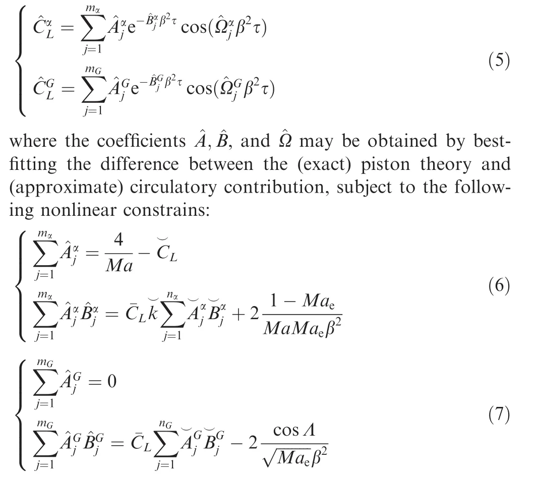
which satisfy the exact initial behavior of piston theory up to a first-order accuracy.
For practical applications,21a single exponential term(i.e.,mα=1 with=0)is often employed for the case of a unit step in the angle of attack,namely:

whereas at least two exponential terms(i.e.,mG=2 with=0 and=0)are necessary for the case of a unit sharp-edged gust,namely:

Table 1 Optimal coefficients for approximating the indicial lift function to a step change in the angle of attack in incompressible flow.

In fact,this simple arrangement departs quite soon from the correct behaviour,17whereas retaining the trigonometric term and letting the approximation pass through the last point given by piston theory at τ=^τ lead to a higher-order accuracy,with:
2.3.Normal front gust
When the front of the sharp-edge gust is normal to the reference airflow,each wing section of a swept wing encounters the gust front at a different time.This effect mitigates the initial lift build-up and shall be taken into account.The entry delay relative to a wing section at the spanwise locationyis geometrically known as τ0=tan Λ ·y/c.Therefore,in the special case of a rectangular wing,the circulatory contribution becomes:
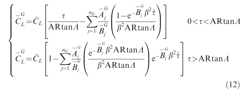
whereas,using a single yet effective exponential term,the noncirculatory contribution reads:

3.Numerical calculation of indicial functions
Two CFD solvers are used to benchmark analytical predictions.The first is the DLR-Tau code,which is widely employed in the European aerospace industry,and the second is Stanford University Unstructured(SU2),an open-source code.
3.1.CFD solvers
The DLR-Tau code is a finite-volume unstructured method which solves the Reynolds-averaged Navier–Stokes equations on cell-vertex metrics.The code is used to solve both steady and unsteady problems,and both dual time stepping and global time stepping are supported for the latter.Explicit and implicit solution algorithms have been implemented,based on Runge–Kutta methods for explicit calculations and an Lower–Upper Symmetric Gauss–Seidel(LU-SGS)method for implicit calculations.The inviscid flux terms can be treated with either central,upwind,or hybrid schemes.Either matrix or scalar dissipation is used to stabilize the convective central difference operators.Viscous terms are treated using a conventional central differencing scheme.The calculations presented in this work were obtained using the dual time stepping approach of Jameson.33The convergence rate was improved with a full multi-grid W-cycle acceleration technique based on agglomerated coarse grids.The original version of the Spalart–Allmaras(S-A)model was used for the turbulence closure.The SU2 software suite34–36is an open-source collection of software tools written in C++and Python for performing multi-physics simulation and design.It is built specifically for the analysis of Partial Differential Equations(PDEs)and PDE-constrained optimization problems on unstructured meshes with state-of-the-art numerical methods,and it is particularly well suited for aerodynamic shape design.The initial applications of the suite were mostly in aerodynamics,but through the initiative of users and developers around the world,SU2.now being used for a wide variety of problems beyond aeronautics,including automotive,naval,and renewable energy applications,to name a few.In all calculations presented,convective fluxes are modelled according to Roe’s scheme37with the Venkatakrishnan limiter.38The standard dual time stepping was used in all cases.The Krylov problem was solved with the FGMRES method and the LU-SGS preconditioner.No multi-grid acceleration was used.The original version of the S-A model has also been used for SU2.
3.2.Unsteady motions
The calculation of indicial responses is carried out for two unsteady motions.One motion corresponds to a step change in the angle of attack,with an amplitude Δα =1.0°.The second motion is for a sharp-edge gust with the vertical component of the velocity,normalized by the freestream speedU∞equal towg=0.0174(approximating the ratio π/180).For both cases,the background steady-state flow solution was calculated at a freestream angle of attack Δα0=0°.
In the DLR-Tau solver,the unsteady motions are performed via a rigid grid-movement approach.Adopting the physical time,t,a generic translation,χ(t),is formulated as:
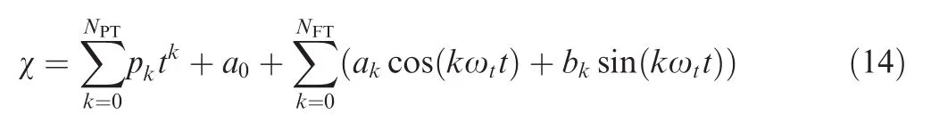
Similarly,a generic rotation,φ(t),is expressed by:
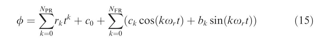
The termsNPTandNPRdenote the number of polynomial coefficients used to model the translation and rotation,respectively.The termsNFTandNFRdenote the number of Fourier coefficients,respectively.In this work,the step change in the angle of attack was forced imposing a constant velocity in the vertical direction (NPT=1,p1=U∞arctan(Δα)).
In SU2 the step change in the angle of attack is also realised by imposing a constant vertical velocity as a rigid body motion.
The gust analysis in DLR-Tau is performed using a gridvelocity approach.9This method modifies the flux balance in the computational domain by an additional disturbance field representative of the prescribed gust.The disturbance is prescribed in the initial field,typically the steady-state solution,and is allowed to move in time depending on the shape and position of the gust.A user can specify the shape of the gust,as a function of thexcoordinate for frontal gusts,ycoordinate for lateral gusts,and timetselecting the global shape between the one-minus-cosine or sharp-edge gust.The gust spatial wavelength and the velocity relative to the frame of reference can also be prescribed as input parameters.
The gust analysis in SU2 follows a different approach:the gust profile is introduced as a perturbation of the initial velocity flow field.The sharp-edge gust front is positioned several hundred chords upstream from the wing leading edge.The perturbation is extended upstream indefinitely,and is propagated towards the wing at the freestream speed.
4.Results
Four con figurations of trapezoidal wings are considered.The geometric parameters include the wing sweep angle,Λ=30°and 0°,and the aspect ratio,AR=8 and 20.The baseline aerofoil,taken parallel to the flow direction,is based on the NACA0006 airfoil which is extruded in the span-wise direction.The wing tip is sharp in all cases,and the corresponding cross-section is parallel to the incoming flow.A schematic of the four wing con figurations is shown in Fig.1.Note that the aspect ratio is given for the tip-to-tip wing geometry,according to the usual convention used in the analytical formulation.For each configuration,the indicial lift response is computed for three Mach numbers(0.3,0.5,and 0.7)for a step change in the angle of attack and for a sharp-edge gust.The Reynolds number,based on the chord,is set to 11.7×10⁶for theMa=0.7 case,and reduced accordingly for the lower-speed cases.In total,24 test cases(four geometric configurations,three Mach numbers,and two responses)involving unsteady simulations are performed.
4.1.Spatial and temporal convergence
Unstructured grids were generated with Point wise and T-Rex as used to create a regular boundary layer off the wing surface.The grid topology contains a far-field boundary condition that is set,on average,at 100 times from the wing surface.Symmetry boundary conditions are set on the vertical plane of symmetry,and the boundary conditions at the wing surface are modelled as adiabatic wall.
To begin with,tests were performed on a set of three grids to ensure that results presented are independent from the spatial discretization.The refinement of the grids was done by increasing systematically the nodes of all connectors by 30%,while the initial wall distance was maintained constant at Δ0=10-6.The spatial convergence check was performed for the AR=20,Λ =0°wing atMa=0.7.The steady state lift coefficients computed using DLR-Tau for the three grids of this convergence study are summarized in Table 3.The termNpindicates the number of grid points.The percentual error is calculated using Richardson’s extrapolation.For the coarse grid,the DLR-Tau results achieve a percentual error smaller than 1%.The grid convergence study was also repeated for SU2 with similar considerations to those already drawn.SU2 predictsCL=0.1049 for the coarse grid,which is less than0.4%of the value from the DLR-Tau solver.This grid was then used in the remainder of the work.
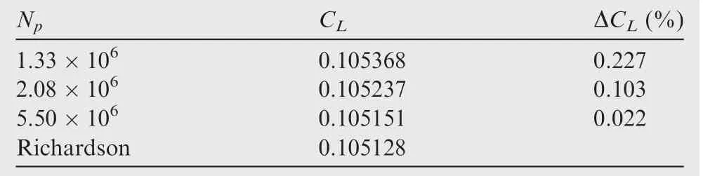
Table 3 Spatial convergence study using DLR - Tau for the AR = 20, Λ =0° wing (α0 =1°, Ma = 0.7).
As computing the initial lift development requires reducing the time-step length with lowering the Mach number,28a second set of tests was run on the selected grid to investigate the temporal convergence of the unsteady responses.Three values of time-step size were considered:0.025,0.05,and 0.1(see Fig.2(a)).Following the traditional procedure,which consists of running at least three unsteady simulations,a nondimensional time step of 0.05 was found adequate for the subsequent studies reported in this work.Furthermore,we have checked the consistency of this conclusion based on the frequency content of the indicial response to a step change in the angle of attack.As an example,Fig.2(b)illustrates the amplitude of the Fourier transform for the AR=8 and Λ =0°wing at a Mach number of 0.3.The transformed signal has a limited frequency content,which decays rapidly for increasing the reduced frequencyK.The saddle point,atK≈0.5,corresponds to the impulsive/circulatory transition of the indicial response.ForK=10,the frequency content decays by about 2 orders of magnitude,as expected.39Based on Nyquist-Shannon sampling theorem,the largest time step to resolve the indicial response forK∈[0,10]is 0.05,which is consistent with the previous consideration.
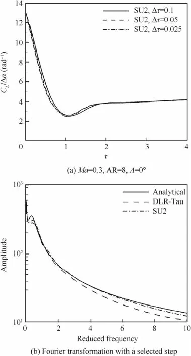
Fig.2 Indicial response to a step change with different nondimensional time steps and Fourier transform with a nondimensional time step of 0.05.
4.2.Indicial response to a step change in the angle of attack
The indicial responses of the lift coefficient to a step change in the angle of attack are shown,for all test cases,in Figs.3 and 4.Each sub-figure consists of two images.The bottom image provides the overall trend of the indicial response up to an asymptotic time,τF=50,while the upper image focuses on the impulsive part of the response,0≤τ≤4.To facilitate cross-comparisons,the upper image also reports a schematic of the corresponding wing configuration.In particular,Fig.3 analyses the impacts of the sweep angle and Mach number for the AR=8 wing,while Fig.4 for the AR=20 wing.The analytical responses usenα=3 andmα=1 terms,respectively,for the circulatory and non-circulatory parts.Based on lifting-line theory,the wing efficiency factor is δ=0.195 for the smaller aspect ratio,and δ=0.334 for the larger one.40
From Figs.3 and 4,it is apparent that the initial value of the indicial response depends solely on the Mach number and is independent on the wing configuration.On the other side,all sources of data are in good agreement for the asymptotic value,which is seen to decrease with the sweep angle as expected from well-known aerodynamic theories.At intermediate times,the qualitative behavior of the indicial response is similar for different sweep angles,and the lowest value in the response is reached at a similar time.Quantitatively,the value of the lower peak depends on the wing sweep,with a smaller value for the swept-wing cases.
Differences between CFD data and analytical predictions become apparent aboveMa=0.5,particularly,for the larger-aspect ratio wing.Despite some differences,the CFD data show a saddle in the indicial response at intermediate times(Fig.3(e)and(f),and Fig.4(e)and(f)),which is not modelled in the analytical function.
4.3.Error quantification in dynamic derivatives predictions
The impact of the observed deviations between analytical and numerical indicial responses is quantified in the context of a realistically important quantity,which is derived from the application of the indicial response allowing the error to be propagated through some intermediate steps.For the significance to aircraft stability and control,41,42the quantification of the error is carried out for the prediction of dynamic derivatives.
In this work,the estimation of dynamic derivatives is obtained by imposing a sinusoidal motion around the pitch axis,which is perpendicular to the incoming flow and located at one quarter of the root chord from the leading edge.The harmonic motion in pitch is defined by the following relation:

where the amplitude is αA=1°,and the reduced frequency isK=0.08.Without resorting to additional(expensive)simulations in the time41or frequency domain,42dynamic derivatives are efficiently(at no extra costs)predicted using the available indicial responses.The following procedure is applied.Firstly,the lift response to a harmonic motion in pitch is computed using the convolution integral for each indicial response(analytical,DLR-Tau,and SU2).One example is shown in Fig.5(a)for the periodic responses,after the initial transients were removed,atMa=0.3 for the AR=8,Λ=0°wing.Then,one of the methods detailed in Ref.42is employed to calculate the dynamic derivatives at the reduced frequency of the forced sinusoidal motion.Herein,emphasis is placed on the prediction of the lift damping coefficient,which consists of two aerodynamic derivatives lumped together:CLq+CLα˙.
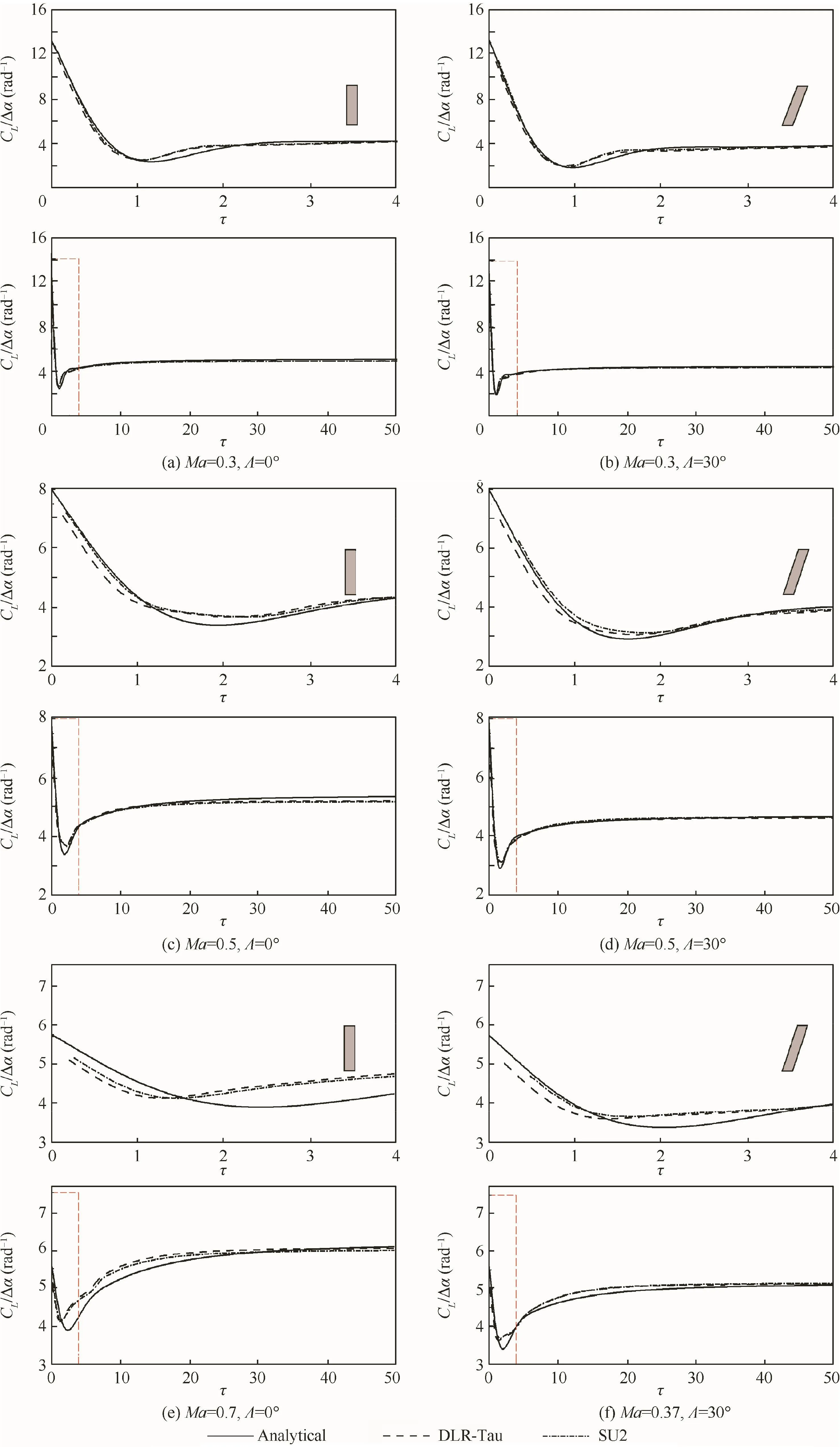
Fig.3 Indicial response of lift coefficients to a step change in the angle of attack(Δα =1.0°)for the AR=8 wing.
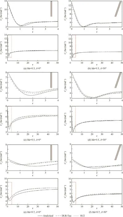
Fig.4 Indicial response of the lift coefficients to a step change in the angle of attack(Δα =1.0°)for the AR=20 wing.
The lift coefficient damping is shown in Fig.5(b)for all test cases.The four wing con figurations are reported along the horizontal axis,with the convention described in Table 4.In the figure,analytical predictions are indicated by filled symbols,and the scatter between CFD-based indicial responses is indicated by error bars.The comparisons evince the good general predictive capability of the analytical approach,but some further comments are worth mentioning.
The first consideration is that the analytical approach captures the impact of the wing planform on the damping coefficient.In particular,increasing the aspect ratio,for a fixed sweep angle,results in a larger damping coefficient,as apparent from the trends that we observe between the first and second wing con figurations,as well as between the third and fourth con figurations.The physical reason for this reflects the increased wetted area which generates the damping contribution.Conversely,for a fixed aspect ratio,increasing the sweep angle reduces slightly the damping coefficient value,as revealed by the trends between the first and third wing configurations,as well as between the second and fourth configurations.It seems plausible that this is related to the reduction of the effective angle of attack for a swept-back wing,compared to an unswept case,due to the offset between the local aerofoil section and the flow direction,which in turn reduces the lift hysteresis loop.
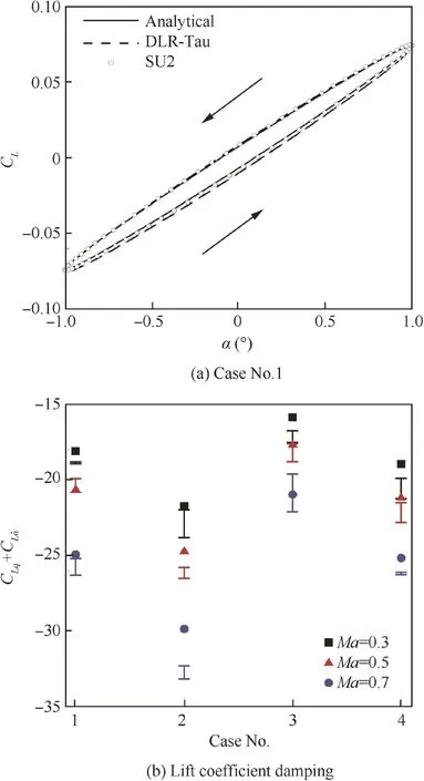
Fig.5 Lift response to a harmonic motion in pitch(α0=1°,K=0.08,Ma=0.3)for the AR=8,Λ=0°wing and lift coefficients damping(filled symbols indicate analytical predictions,while error bars the scatter between CFD data).
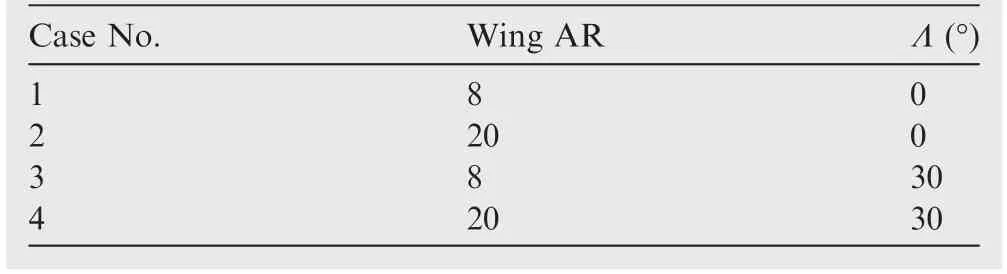
Table 4 Convention to denote wing configurations as labelled in Fig. 5(b).
The scatter in dynamic derivatives,which are computed from CFD-based indicial responses,reflects the associated reliability or uncertainty in the usage of current state-of-the-art CFD solvers for unsteady analyses.The aerodynamic uncertainty in the estimation of dynamic derivatives is relatively large,in specific,when confronted with:(A)the background tests performed to minimize the effects of the spatial and temporal resolutions,as documented in Section 4.1;and(B)the benign conditions of the attached flow(linear steady,linear unsteady)herein considered.It is therefore encouraging to ascertain from Fig.5(b)that the uncertainty associated with the analytical predictions is equivalent to that arising when different CFD solvers are used and compared.The computational cost of the analytical predictions is,however,negligible compared to that needed by the numerical predictions.For reference,SU2 results were computed in about 200 CPU hours.
The procedure to obtained dynamic derivatives from the CFD-based indicial responses is equivalent to that based on the linear frequency domain.42Both approaches exploit the assumption of linearity around a(nonlinear)steady state solution.Therefore,conclusions drawn from Fig.5(b)are independent of the particular(indicial)approach used in this study and conf i rm the general predictive capability of the analytical approach.
4.4.Indicial response to a sharp-edge gust
To the authors’best knowledge,the open literature on the calculation of an indicial response due to a sharp-edge gust is extremely scarce for a three-dimensional wing geometry.In this context,the work reported in this paper provides a thorough study that expands the available background knowledge on indicial functions due to gust for a number of three dimensional wings.This may be considered the first study in the area,combining analytical and computational techniques.Figs.6 and 7 show the results for all test cases,where the analytical responses usenG=4 andmG=2 terms.In particular,the indicial responses of the lift coefficient to a sharp-edge gust for the un swept wing cases(Λ =0°)are shown in Fig.6,while those for the swept wing cases(Λ =30°)in Fig.7.
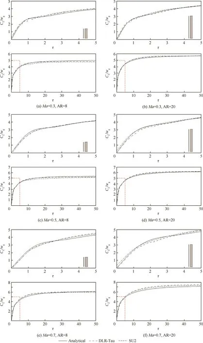
Fig.6 Indicial response of the lift coefficients to a sharp-edge gust for Λ =0° wings.
To begin with,the lift built-up for the unswept wing cases reveal a strong similarity between the AR=8 and 20 wings.Small deviations are found between the three aerodynamic sources,but generally the overall agreement is satisfactory.For small times,spurious oscillations appear in the solution obtained using the DLR-Tau code.This is not unexpected,as already observed and discussed in the literature.11However,it is unexpected that the numerical artefact is solver-dependent,and that SU2 predicts a smooth gust/wing interaction.

Fig.7 Indicial response of the lift coefficients to a sharp-edge gust for Λ =30° wings.
For the swept wing cases,Fig.7 reveals an excellent agreement between the analytical predictions and the computational data.The gradual penetration of the gust front over the wing surface introduces a delay in the lift built-up.Observe that the zoomed area,shown in the upper image of each figure,is for 0<τ<15 three times larger than the corresponding zoomed area for the unswept cases in Fig.6.The resulting gust/wing interaction occurs at a lower rate than that for the unswept wing cases,but no spurious oscillations were produced by either CFD code.The reason for this may be attributed to the misalignment between the gust front and the grid elements of the wing surface that develop parallel to the wing leading edge.
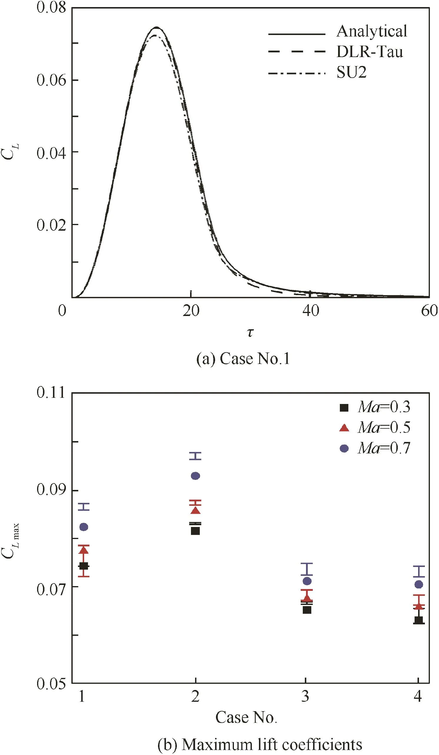
Fig.8 Lift coefficients response to a one-minus-cosine gust(wg0= π/180,Hg=25,Ma=0.3)for the AR=8 and Λ =0°wing and maximum lift coefficient(filled symbols indicate analytical predictions,while error bars the scatter between CFD data).
5.Error quantification in response to discrete gust
The one-minus-cosine family of gusts is prescribed by certification authorities for structural sizing of aircraft components.Here,we consider the corresponding aerodynamic problem by neglecting the structural side of the coupled problem.This is justified because an assessment of the recent analytical development is needed in the first place.
The nondimensional vertical velocity of a one-minus-cosine gust is modelled as:

Herein,the focus is for a gust withwg0=π/180 andHg=25.The procedure followed consists of two steps.Firstly,the convolution integral is calculated using the available indicial responses from the three aerodynamic sources(analytical,DLR-Tau and SU2 An example is shown in Fig.8(a)for the lift coefficient response obtained for the AR=8 and Λ =0°wing.The second step is the identification of the maximum lift coefficient value,CLmax,that corresponds to the peak in the response.The maximum lift coefficient recorded for all test cases is illustrated in Fig.8(b).
The uncertainty in the CFD-based aerodynamic predictions is somewhat similar to the deviation of the analytical results from the computational ones.For the unswept wings(Cases 1 and 2),CLmaxwas found to increase for increasing aspect ratio.This ubiquitous trend is a result of the three dimensionality of the flow:for the shorter wing,the intensity of the tip vortex is stronger,generating a larger(negative)induced angle of attack that partly reduces the effect of the gust encounter.On the contrary,the flow around the slender wing of AR=20 is more two-dimensional,with the tip vortex affecting a relatively smaller portion of the wing surface.
For the swept wings(Cases 3 and 4),the aspect ratio has a negligible influence on the maximum lift coefficient.The reason for this is attributed to the similarity between the gust nondimensional length,Hg=25,and the extent of the AR=20,Λ=30°wing in the downstream direction,that is ARtanΛ≈17.As the gust moves over the wing surface,some areas of the wing may be contemporarily exposed to the left and right ends of the one-minus-cosine gust where the intensity is small,and an isolated part of the wing surface experiences the peak gust.
Finally,it should be expected that the time at which the lift coefficient response reaches the largest peak is case-dependent.In particular,the wing sweep angle delays the occurrence,as readily evident from the indicial responses in Section 4.4.
6.Conclusions
(1)Indicial aerodynamics,whether in a linear or nonlinear flavour,remains a convenient modelling technique considering increased manoeuvre capabilities and expanded fight envelopes of modern aircraft.However,the derivation of indicial aerodynamics often relies on either strong limiting assumptions,such as thin aerofoil theory,or excessing demands in terms of computing power and experimental testing.This is the motivation for the present work,which looks at an effective generation of analytical indicial functions.
(2)This work discusses the formulation of an analytical indicial aerodynamics method that extends well-known theories,which are based on the assumption of thin aerofoils,to generic trapezoidal wings of finite span in subsonic flow.Within the chosen analytical method,indicial functions are expanded in series of exponential functions,with coefficients determined by minimising the deviations from the known analytical solutions for incompressible flow.
(3)The analytical formulation is then applied to predict the responses to a step change in the angle of attack and to a sharp-edge gust.Test cases include four wing planforms,with different aspect ratios and sweep angles,at three Mach numbers between 0.3 and 0.7.Two state-of-theart computational fluid dynamics solvers(DLR-Tau and SU2)are used to benchmark analytical predictions for alltest cases.Numerical assessments rely on unsteady Reynolds-averaged Navier–Stokes equations with the Spalart–Allmaras turbulence model.Results presented are deemed accurate following spatial and temporal convergence studies.
(4)The first finding of this work is that there is a reasonable agreement between the analytical and computational indicial responses for all test cases.Larger deviations are found within the impulsive/circulatory transition of the responses.
(5)Next,attention is addressed at assessing the impact of the observed deviations on the predictions of dynamic derivatives and the maximum lift coefficient following an encounter with a one-minus-cosine gust.Dynamic derivatives are computed from available indicial responses to a step change in the angle of attack,and the maximum lift coefficient using the indicial responses to a sharp-edge gust.
(6)The scatter observed in the computational results is represented with an error bar,representing an equivalent uncertainty in computational aerodynamics.The advantage in doing this is that the deviation of the analytical predictions from the computational results is confronted directly with the scatter or uncertainty arising between the two computational solvers.
(7)It is encouraging to ascertain the good predictive capability of the proposed analytical formulation,with results that fall within the scatter or uncertainty in the computational values for a good number of test cases.This becomes even more pronounced when balanced against computing costs,with the computational results obtained on high-performance computing facilities(200 CPU hours for each unsteady analysis)and after various convergence checks(spatial and temporal).
Acknowledgements
Da Ronch would like to express his sincere appreciation to the Royal Academy of Engineering for funding this research and acknowledges the use of the IRIDIS High Performance Computing Facility,and associated support services at the University of Southampton,in the completion of this work.Righi gratefully acknowledges the computational resources made available by the Swiss National Supercomputing Centre.
Data supporting this study are openly available from the University of Southampton repository at https://doi.org/10.5 258/SOTON/D0101.
Appendix A.Indicial lift for incompressible flow
A single vortex-ring models the total wing circulation,with both bound and shed vortices parallel to the quarter-chord line and both tip vortices parallel to the freestream.All(lumped)vortices own the same intensity,within the simplest implementation of the lifting-line theory.A single control point is then placed at the third-quarter chord of the wing root,where the non-penetration boundary condition is imposed via Kutta-Joukowsky theorem and Biot-Savart law.43The shed vortex moves towards inf i nity at half the reference airspeed from half root-chord behind the control point,thus increasing the wake length and stretching the vortex-ring.After several travelled chords,its influence eventually disappears and a steady lift is asymptotically obtained.The root chord is used as the reference length for the reduced(non-dimensional)time τ The lift build-up due to a unit step in the angle of attack then reads:20

Fig.A1 Indicial lift function in incompressible flow(Symbols denote the original curves).

where the denominators associated with bound,trailed,and shed vortices are:leading to
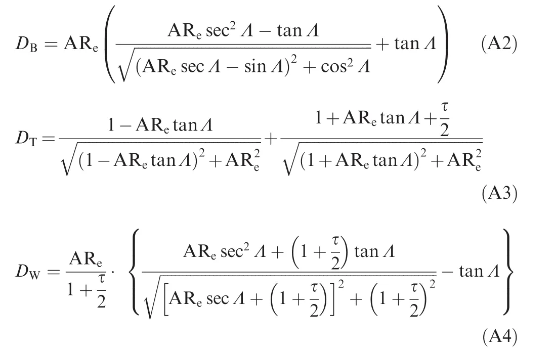
Within the ‘frozen gust” framework,23,the lift build-up due to a unit sharp-edge gust with perturbation front parallel to the wing leading edge may then be obtained as:
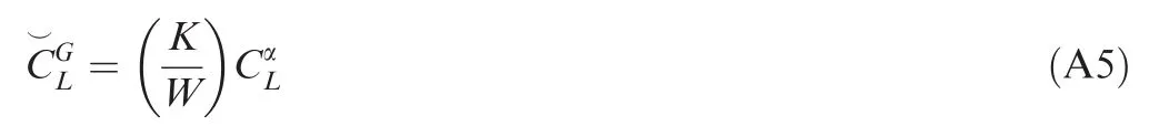
whereKandWare Küssner’s7and Wagner’s5functions,respectively,the ratio of which introduces the gust penetration effect.25Note that this expression may hold for the case of compressible flow as well;24however,all approximation coefficientsandare then Mach number-dependent.28
Finally,Fig.A1 shows the approximate and original curves considered in this study(see Tables 1 and 2).
1.Murphy PC,Klein V,Frink NT.Nonlinear unsteady aerodynamic modeling using wind tunnel and computational data.J Aircraft2017;54.https://doi.org/10.2514/1.C03388.
2.Reisenthel PH,Bettencourt MT,Myatt JH,Grismer DS.A nonlinear indicial prediction tool for unsteady aerodynamic modeling.Reston:AIAA;1998.Report No.:AIAA-1998-4350.
3.Volterra V.Theory of functionals and of integral and integro differential equations.New York:Dover Publications,Inc.;1959.
4.Wiener V.Response of a non linear device to noise.Massachusetts:MIT Radiation Laboratory;1942.Report No.:129.
5.Wagner H.Üeber die Entstehung des dynamischen Auftriebes von Tragügeln.Zeitschrift für Angewandte Mathematik und Mechanik1925;5(1):17–35.https://doi.org/10.1002/zamm.19250050103.
6.Theodorsen T.General theory of aerodynamic instability and the mechanism of flutter.Washington,D.C.:NASA;1935.Report No.:NACA 496.
7.Küssner HGK.Stresses produced in airplane wings by gusts.Washington,D.C.:NASA;1932.Report No.:NASA TM 654.
8.Sears WR.Some aspects of non stationary airfoil theory and its practical application.J Aeronaut Sci1941;8(3):104–8.
9.Parameswaran V,Baeder JD.Indicial aerodynamics in compressible flow-direct computational fluid dynamic calculations.J Aircraft1997;34(1):131–3.
10.Ghoreyshi M,Cummings RM,Da Ronch A,Badcock KJ.Transonic aerodynamic loads modeling of X-31 aircraft pitching motions.AIAA J2013;51(10):2447–64.https://doi.org/10.2514/1.J052309.
11.Da Ronch A.On the calculation of dynamic derivatives using computational fluid dynamics[dissertation].Liverpool:University of Liverpool;2012.
12.Klein V,Noderer KD.Modeling of aircraft unsteady aerodynamic characteristics,Part I:postulated models.Washington,D.C.:NASA;1994.Report No.:NASA TM 109120.
13.Klein V,Murphy PC,Curry TJ,Brandon JM.Analysis of wind tunnel longitudinal static and oscillatory data of the F16XL aircraft.Washington,D.C.:NASA;1997.Report No.:NASA TM 97 206276.
14.Gupta NK,Ili KW.identification of aerodynamic indicial functions using flight test data.Reston:AIAA;1982.Report No.:AIAA-1982-1375.
15.Myatt JH.Modeling the rolling 65 degree delta wing with critical state encounters.Reston:AIAA;1997.Report No.:AIAA-1997-3646.
16.Reisenthel PH.Application of nonlinear indicial modeling to the prediction of a dynamically stalling wing.Reston:AIAA;1996.Report No.:AIAA-1996-2493.
17.Righi M,Koch J,Berci M.Subsonic indicial aerodynamics for unsteady loads calculation via numerical and analytical methods:A preliminary assessment.Reston:AIAA;2015.Report No.:AIAA-2015-3170.
18.Gothert BH.Plane and three-dimensional flow at high subsonic speeds(extension of the prandtl rule).Washington,D.C.:NASA;1946.Report No.:NACA TM 1105.
19.Pike EC.Manual on aeroelasticity.Paris:AGARD;1971.Report No.:AGARD 578.
20.Queijo MJ,Wells WR,Keskar DA.Approximate indicial lift function for tapered,swept wings in incompressible flow.Washington,D.C.:NASA;1978.Report No.:NASA TP 1241.
21.Leishman JG.Principles of helicopter aerodynamics.Cambridge:Cambridge University Press;2006.
22.Jones RT.The unsteady lift of a wing of finite aspect ratio.Washington,D.C.:NASA;1940.Report No.:NASA 681.
23.Hoblit FM.Gust loads on aircraft:Concepts and applications.Reston:AIAA;1998.
24.Mazelsky B.Numerical determination of indicial lift of a two dimensional sinking airfoil at sub-sonic Mach numbers from oscillatory lift coefficients with calculations for Mach number 0.7.Washington,D.C.:NASA;1951.Report No.:NACA TN 2562.
25.Chiang HWD,Fleeter S.Prediction of loaded airfoil unsteady aerodynamic gust response by a locally analytical method.Math Comput Modell1988;11:871–6.
26.Prandtl L.Applications of modern hydrodynamics to aeronautic.Washington,D.C.:NASA;1921.Report No.:NACA TR 116.
27.Wieseman CD.Methodology for matching experimental and computational aerodynamic data.Washington,D.C.:NASA;1988.Report No.:NACA TM 100592.
28.Berci M,Righi M.An enhanced analytical method for the subsonic indicial lift of two dimensional aerofoils with numerical cross-validation.Aerosp Sci Technol2017;67:354–65.
29.Bendiksen O.Review of unsteady transonic aerodynamics:theory and applications.Progress Aerosp Sci2011;47:135–67.
30.Sears WR.Operational methods in the theory of airfoils in nonuniform motion.J Franklin Inst1940;230(1):95–111.
31.Berci M.Optimal approximations of indicial aerodynamics.1st international conference on engineering and applied sciences optimization,2014.
32.Lomax H,Fuller FD,Sluder L.Two-and three-dimensional unsteady lift problems in high-speed flight.Washington,D.C.:NASA;1952.Report No.:NACA 1077.
33.Jameson A.Transonic flow calculations[dissertation].Princeton:Princeton University;1983.
34.Palacios F,Colonno MR,Aranake AC,Campos A,Copeland SR,Economon TD,et al.Stanford University unstructured(SU2):an open-source integrated computational environment for multiphysics simulation and design.Reston:AIAA;2013.Report No.:AIAA-2013-0287.
35.Palacios F,Economon TD,Aranake AC,Copeland SR,Lonkar AK,Lukaczyk TW,et al.Stanford University unstructured(SU2):open-source analysis and design technology for turbulent flows.Reston:AIAA;2014.Report No.:AIAA-2014-0243.
36.Economon TD,Palacios F,Copeland SR,Lukaczyk TW,Alonso JJ.SU2:An open-source suite for multiphysics simulation and design.AIAA J2015;54(3):828–46.
37.Roe PL.Approximate Riemann solvers,parameter vectors,and difference schemes.J Comput Phys1981;43(2):357–72.
38.Venkatakrishnan V.On the accuracy of limiters and convergence to steady state solutions.Reston:AIAA;1993.Report No.:AIAA-1993-0880.
39.Venkatesan C,Friedmann P.New approach to finite-state modeling of unsteady aerodynamics.AIAA J1986;24(12):1889–97.
40.Nita M.Contributions to aircraft preliminary design and optimization[dissertation].Hamburg:Hamburg University of Applied Sciences;2012.
41.Da Ronch A,Vallespin D,Ghoreyshi M,Badcock KJ.Evaluation of dynamic derivatives using computational fluid dynamics.AIAA J2012;50(2):470–84.https://doi.org/10.2514/1.J051304.
42.Da Ronch A,McCracken AJ,Badcock KJ,Widhalm M,Campobasso MS.Evaluation of dynamic derivatives using computational fluid dynamics.J Aircraft2013;50(3):694–707.https://doi.org/10.2514/1.C031674.
43.KatzJ,PlotkinA.Lowspeedaerodynamics.Cambridge:Cambridge University Press;2001.
杂志排行

CHINESE JOURNAL OF AERONAUTICS的其它文章
- Time-varying linear control for tiltrotor aircraft
- Global aerodynamic design optimization based on data dimensionality reduction
- Mesh deformation on 3D complex configurations using multistep radial basis functions interpolation
- Stagnation temperature effect on the conical shock with application for air
- Transient simulation of a differential piston warm gas self-pressurization system for liquid attitude and divert propulsion system
- Effects of tube system and data correction for fluctuating pressure test in wind tunnel