Lock threshold deterioration induced by antenna vibration and signal coupling effects in hypersonic vehicle carrier tracking system of Ka band
2018-04-21CongyingZHULeiSHIXiaopingLIYanmingLIUWeiAI
Congying ZHU,Lei SHI,Xiaoping LI,Yanming LIU,Wei AI
School of Aerospace Science and Technology,Xidian University,Xi’an 710071,China
1.Introduction
Serious challenges are encountered during the transmission of information between hypersonic vehicles and the ground Tracking Telemetry and Command(TT&C)station.For instance,thin-walled structures are extensively used in the structural design of hypersonic vehicles to reduce weight.1–3However,a thin-walled structure can withstand high-level acoustic load because the engine jet noise is combined with aerodynamic noise.4–9And,severe fluctuating pressure is produced by the acoustic load and causes the thin-walled structure to vibrate.Therefore,the airborne antenna is likely to vibrate slightly because of structure vibration.Antenna vibration can mix with the signals transmitted by the airborne antenna,and a rapid change in the signal phase occurs;these conditions result in parasitic phase modulation effects.Given the short wavelength of Ka band signals(mostly less than 1 cm),the coupling phenomenon is harmful to the transmission of Ka band phase modulated signals,especially coherent demodulation in the TT&C tracking system,and causes degradation of the communication performance.
The structural vibration of hypersonic vehicles has been extensively investigated in previous studies.Suzukiand Abe10conducted aerodynamic tests on a reentry blunt cone under the conditions of near-sonic,supersonic,and hypersonic speeds.The aerodynamic characteristics of the aircraft were obtained mainly from the viewpoint of system stability.Bolender et al.11studied the effect of unsteady viscoelastic aerodynamics on the aerodynamic characteristics of an aspirated hypersonic vehicle,and the unstable boundary conditions were provided.Rizzi and Robinson12investigated the dynamic response of hypersonic vehicles at the NASA Langley Research Center and provided the corresponding fluctuating pressure spectra.However,the corresponding results for the vibration response of the aircraft were not sufficiently considered.Fortunately,the vibration response of an aircraft can be calculated based on fluctuating pressure.An accurate vibration model is crucial in investigating the influence of this coupling phenomenon on carrier tracking performance.In 2007,Kim et al.13examined the interaction between hypersonic vehicle structures and shock disturbances in the presence of acoustic load,and the vibration response was determined.It can be seen that the aerodynamic characteristics of hypersonic vehicles have been extensively investigated,and the structural dynamic response has been obtained.Nevertheless,the coupling effects between airborne antenna vibration and communication signalsare yetto be evaluated.A coherent demodulation mode is generally adopted in the actual transmission process of TT&C signals.Carriers locked precisely at a low-input SNR are essential for reliable communication,and the influence of this coupling effects on carrier tracking should be considered.This paper investigates the coupling effects and its influence on carrier tracking,especially two classic phase-modulated signals of Ka band.The effect of this phenomenon on PLL lock threshold is quantitatively analyzed in detail.Quantitative analysis results can provide a reference for actual system design and engineering applications.
Theoretical results on the lock threshold of PLL are complex because of the multiplicative nature of phase noise;however,these results have been rarely obtained.The influence of this phenomenon is quantitatively investigated through simulation,compared,and verified with that obtained through a basic theoretical analysis.This paper is divided into the following parts.Section 2 investigates the coupling effects between airborne antenna vibration and tracking signals by establishing a vibration model and determining the phase noise.Section 3 presents the analytical model of PLL with multiplicative phase noise.Phase noise is imposed on the PLL model for further analysis in Section 4.The last section provides the conclusions.
2.Coupling effects between airborne antenna vibration and tracking signals
2.1.Airborne antenna vibration model
Hypersonic vehicles,the speeds of which reach 5 Mach or above,are affected by engine jet noise combined with aerodynamic noise.The thin-walled structure of such vehicles withstands high-level acoustic load.Furthermore,interaction exists between the structure and the shock wave.Kim et al.13investigated the interaction between hypersonic vehicle structures and shock disturbances in the presence of acoustic load.The power spectrum of vibration displacement was provided(see Fig.1).The flight condition is that the flight speed is 5 Mach,the acoustic load is 120.2 dB,the angle between the shock and the wall is 4°,and the flight altitude is 17 km.The frequency-domain data of vibration displacement are obtained through the periodogram method using the power spectrum.The inverse Fourier transform technique is adopted to obtain vibration displacement data in the time domain(see Fig.2).
With the power spectrum provided by Ref.13,the first-order statistics of vibration displacement are obtained.The Probability Density Function(PDF)of the vibration displacement is shown in Fig.3.The statistical law of vibration displacement is similar to that of Gaussian distribution.The mean value is 0,and the standard deviation is 1.2744×10⁻⁴m.

Fig.1 Power spectrum obtained from Ref.13.

Fig.2 Time domain data after processing(areodynamic reposnse).
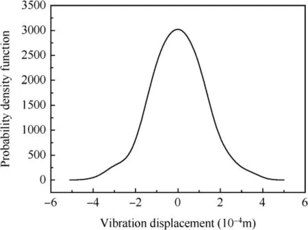
Fig.3 Probability density function of obtained vibration displacement.
2.2.Multiplicative phase noise caused by airborne antenna vibration
The patch antenna is widely used in hypersonic vehicles.As such,the assumption that airborne antenna vibration is similar to aircraft structure vibration is reasonable.Propagation distance and the signal phase have the following fixed coupling relation when the electromagnetic wave propagates in the atmosphere.

whereL(t)is the propagation distance,i.e.,the vibration displacement;λ is the wavelength of the electromagnetic wave;β is the angle of the vibration direction and direction of propagation.The worst case,that is,vibration in the same direction of propagation(β =0°)is under consideration in the paper.And a 30 GHz carrier signal for the tracking systems is considered.Hence,Δθ(t),which is the parasitic phase noise,can be obtained with the vibration displacement obtained above,as illustrated in Eq.(2).

Considering that the airborne antenna can vibrate with different standard deviations,we obtain the PDF of the parasitic phase noise with different standard deviations,as shown in Fig.4,where σ,normalized by the carrier wavelength,is the standard deviation of the vibration displacement.
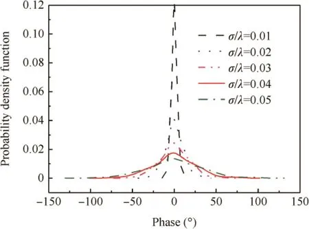
Fig.4 Probability density function of parasitic phase noise with different standard deviations.
The phase noise caused by airborne antenna vibration also presents a Gaussian distribution due to the linear relationship with vibration displacement.This phase noise is multiplicative.The mean value is steady at zero degree despite the standard deviation of vibration displacement;however,a large standard deviation of vibration displacement results in a large standard deviation of phase noise.Multiplicative phase noise affects the tracking system in a different manner,and the lock threshold of PLL increases.The phase analytical model of PLL with this type of multiplicative phase noise is initially established,and the phase noise with different standard deviations of vibration displacement is imposed on it for further analysis.
3.Analytical model of PLL with multiplicative phase noise
The phase analytical model of PLL with the influence of airborne antenna vibration is shown in Fig.5.In the presence of parasitic phase noise,the input carrier and output signals can be expressed as follows:

whereAis the amplitude of the input carrier signal,ω is the carrier angular frequency,ω0is the initial angular frequency of the oscillator,θ1(t)is the phase of the carrier,θ2(t)is the phase of the oscillator, θ1(t)= θ1+Δθ(t),and Δθ(t)is the phase noise caused by antenna vibration.
The input additive Gaussian white noiseN(t)can be written as14

whereN1(t)andN2(t)are independent Gaussian random processes with one-sided power spectral density ofN0w/cps.
The differential equation of PLL can be obtained as
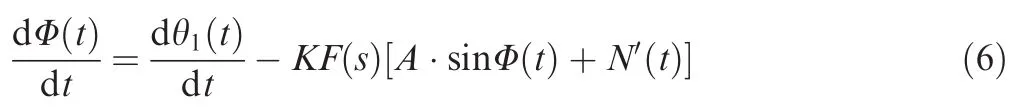
where φ(t)is the phase error between the input and output signals,φ(t)= θ1(t)- θ2(t),N′(t)is the equivalent input Gaussian white noise,andKis the gain.N′(t)=-N1(t)sin θ2(t)+N2(t)cos θ2(t),andF(s)is the transfer function of the loop filter.
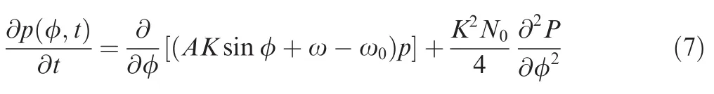
In the basic theoretical analysis for the second-order loop,input carrier frequency ω that is equal to the initial frequency of the oscillator,that is,ω=ω0,and the initial condition,which is φ(t=0)=θ1,are assumed.15The input Gaussian white noise is the only factor that affects the status of PLL.φ(t)is a continuous Markov process16,and random walk techniques are used to determine its probability distribution.The theoretical lock threshold is obtained by solving the partial differential equation ofP(φ,t)as follows:
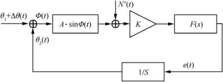
Fig.5 Phase analytical model of PLL with parasitic phase noise.
The steady-state probability distribution of the phase error in the linear model,that is,sin φ(t)≈ φ(t),can be obtained as
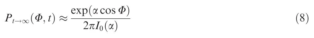
The frequency of skipping cycles is expressed as follows:

whereI0is a zero-order Bessel function,α is the loop SNR,andBLis the loop noise bandwidth.α is obtained as follows:

The relationship between loop SNR and input SNRiis as follows17:
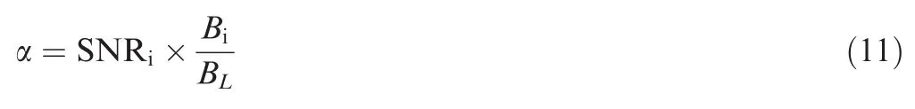
whereBiis the bandwidth of the pre-BPF.When α is equal to zero with additive Gaussian white noise,the frequency of skipping cycles is 1,which is defined as the threshold of the loss of lock.18
The loop noise bandwidth must be sufficiently small to track the carrier signal precisely under the condition of low input SNR,but this condition is contradictory to the demands for a short lock time,which requires a largeBL.19,20A PLL with good comprehensive performance is designed in this study,and the parameters of the model areBL=100 Hz andBi=450 Hz.For research convenience,this study considers the input SNR to characterize the lock threshold.
4.Results and discussion
4.1.Lock threshold without antenna vibration
The lock probability of PLL is a widely used tool to analyze the status of PLL,and it is used in the following section to make a quantitative analysis.The lock probability of PLL without antenna vibration(Gaussian white noise only)is shown in Fig.6.The lock threshold is SNRi=-15 dB when the reference signal is the Ka band single-frequency signal.That is,the PLL cannot be locked with the probability of 1 when the input SNRiis less than-15 dB.The simulation result is generally consistent with that of the theoretical analysis.

Fig.6 Lock probability without aircraft structure vibration.
The lock thresholds of phase-modulated signals are higher than those of single-frequency signals because of the nonlinear operation before carrier extraction.In Fig.6,the lock thresholds for BPSK and QPSK signals are SNRi=-12 dB and SNRi=-4 dB,respectively.
4.2.influence of antenna vibration and signal coupling effects on phase-modulated signals
4.2.1.Quantitative analysis of BPSK signals
The simulation condition is that the standard deviation of vibration displacement is 0.01λ and the intensity of input Gaussian white noise compared with that of the input signal is-12 dB,which is the critical value without vibration.A set of simulation results on the phase error between the output signal of PLL and the in-phase carrier signal is illustrated in Fig.7.
The PLL is locked without vibration(solid line in Fig.7),that is,the phase error remains at zero degree.A skipping cycle phenomenon,namely,the phase error increases to about-180°from 0°,occurs at about 0.9 s(dash line in Fig.7).This means that the output signal cannot be used to demodulate the transmitted information with the influence of vibration.The Bit Error Rate(BER)increases,which in turn degrades the communication performance.
The influence of this coupling effects on the lock threshold of PLL for BPSK signals is quantitatively analyzed under different standard deviations,which are normalized by the wavelength of the electromagnetic wave,of vibration displacement(see Fig.8).As shown in Fig.8,a large standard deviation results in a significant effect on the lock threshold.The standard deviation normalized by the wavelength,which is σ/λ,must be lower than 0.04 to ensure that the PLL is locked.Under these conditions,the PLL can relock with the probability of 1 by improving the input SNR.However,the PLL could become completely disabled if σ/λ is greater than 0.04.
4.2.2.Quantitative analysis of QPSK signals
A set of simulation results for QPSK signals on the phase error between the output signal and in-phase carrier is shown in Fig.9.The simulation condition is that SNRi=-4 dB,which is the critical value without vibration,and the standard deviation of vibration displacement is also 0.01λ.

Fig.7 Phase error of output and reference carriers.

Fig.8 Lock threshold with vibration for BPSK signals.

Fig.9 Phase error for QPSK signals.

Fig.10 Lock threshold with vibration for QPSK signals.
As illustrated above,the lock threshold without vibration for the receiver of QPSK signals is-4 dB.A fluctuation phenomenon of phase error is observed in the presence of antenna vibration(dash line in Fig.9).This indicates that PLL performance is affected by airborne antenna vibration.
The influence of airborne antenna vibration on the lock threshold of PLL for QPSK signals is quantitatively analyzed under different standard deviations(see Fig.10).The critical value of σ/λ is reduced to 0.02,which means that the influence of antenna vibration on the PLL of QPSK signals is more severe than that on BPSK signals.
An interesting phenomenon is that ups and downs are observed in the lock probability when σ/λ is greater than the critical value.This phenomenon is mainly attributed to the random characteristics of the parasitic phase noise.The phase noise caused by the airborne antenna vibration and the Gaussian white noise exerts a canceling effect,thus improving the lock probability in several cases.
Table 1 is prepared based on Figs.8 and 10 to quantitatively characterize the influence of airborne antenna vibration with different standard deviations on carrier tracking performance.The airborne antenna vibration affects the lockout threshold of PLL when σ/λ is greater than 0.01 for BPSK signals and σ/λ greater than 0.02 for QPSK signals.The effect exacerbates as σ/λ increases.However,a maximum σ/λ in the two types of signals can be tolerated by PLL.If σ/λ is greater than the maximum σ/λ,then the PLL cannot relock by improving the input SNR of the received signals.The critical value of the receiver of QPSK signals,which is only 0.02,is smaller than that of the BPSK signals.The simulation results indicate that the effect of antenna vibration on the performance of the QPSK signals is more severe than that on the BPSK signals.
5.Conclusions
Hypersonic vehicles encounter a very complicated environment,in which significant challenges are present during the transmission of information.Among these challenges is the structure vibration caused by fluctuating pressure.The airborne antenna vibrates due to structure vibration.The coupling effects between the vibration of the mechanism and the communication signals were comprehensively investigated in this study.A vibration model was initially established.This study focused on the effect on the TT&C tracking system.The coupling effects on the lock condition of the hypersonic vehicle carrier tracking system of the Ka band were quantitatively analyzed for BPSK and QPSK signals.The simulation results indicated that the vibration displacement presented a Gaussian distribution.The multiplicative phase noise caused by airborne antenna vibration also presented a Gaussian distribution due to the linear relationship with vibration displacement.A large standard deviation of vibration displacement exerted a significant effect on the lock threshold.A critical vibration standard deviation was observed in the two typesof signals.The effect on the QPSK receivers was more severe than that on the BPSK receivers.The receivers could become completely disabled if the vibration standard deviation is greater than the critical values.The results can help in selecting the optimal demodulation algorithm to improve the stability of communication systems.

Table 1 influence of airborne antenna vibration on lock threshold.
However,the vibration model was established under the condition that the flight speed is 5 Mach.Circumstances with different flight speeds should be considered comprehensively.A difference exists between airborne vibration and structure vibration.This difference should also be considered.Many options need to be investigated in the future.For example,the CFD software can be used to establish the airborne antenna vibration model under different conditions,and a Verification experiment could be implemented.
Acknowledgements
This work was co-supported by the National Basic Research Program of China(No.2014CB340205),the Natural Science Foundation of Shaanxi Provincial Department of Education(No.2016JM6016),and the National Natural Science Foundation of China(No.61473228).
1.Wagner JL,Yuceil KB.Experimental investigation of unstart in an Inlet/isolator model in Mach 5 Flow.AIAA J2010;48(9):1875–88.
2.Peng WG,He YR,Wang XZ,Zhu JQ,Han JC.Thermal protection mechanism of heat pipe in leading edge under hypersonic conditions.Chin J Aeronaut2015;28(1):121–32.
3.Nicholson J.Oblique blast wave interaction with a supersonic vehicle.Aerospace sciences meeting;1967 Jan 23–26;New York.Reston:AIAA;1967.p.67–180.
4.Chassaing JC,Lucor D,Tregon J.Stochastic nonlinear aeroelastic analysis of a supersonic lifting surface using an adaptive spectral method.J Sound Vib2012;331:394–411.
5.Hu ZM,Myong RS,Wang C,Cho TH,Jiang ZL.Numerical study of the oscillations induced by shock/shock interaction in hypersonic double-wedge flows.Shock Waves2008;18(1):41–51.
6.Do H,Im SK,Mungal MG.The influence of boundary layers on supersonic inlet flow unstart induced by mass injection.Exp Fluids2011;51(3):679–91.
7.Chou YS,Laitone EV.Phugoid oscillations at hypersonic speeds.AIAA J2015;3(4):732–5.
8.Chen X,Liu L,Long T,Yue ZJ.A reduced order aerothermodynamic modeling framework for hypersonic vehicles based on surrogate and POD.Chin J Aeronaut2015;28(5):1328–42.
9.Li K,Liu J,Liu WG.A new surface catalytic model for silicabased thermal protection material for hypersonic vehicles.Chin J Aeronaut2015;28(5):1355–61.
10.Suzuki K,Abe T.Transonic,supersonic and hypersonic windtunnel tests on aerodynamic characteristics of reentry body with blunted cone configuration.Inst Space Astronaut Sci Report1995;658:1–25.
11.Bolender M,Oppenheimer M,Doman D.Effects of unsteady and viscous aerodynamics on the dynamics of a flexible air-breathing hypersonic vehicle.AIAA atmospheric flight mechanics conference and exhibit;2007 Aug 20–23;Hilton Head.Reston:AIAA;2007.p.1–18.
12.Rizzi S,Robinson J.Dynamic response and sonic fatigue analysis at NASA Langley for hypersonic vehicle structures.AlAA fourth international aerospace planes conference;1992 December 1–4;Orlando.Reston:AIAA;1992.p.1–10.
13.Kim KK,Kim YC,Migholet MP,Liu DD.Random aeroelastic response due to strong hypersonic unsteady-wave/shock interaction with acoustic loads.AIAA/ASME/ASCE/AHS/ASC structures,structural dynamics,and materials conference;2007 Apr 23–26;Honolulu.Reston:AIAA;2007.p.1–10.
14.Musa A,Deng W,Siriburanon T,Miyahara M,Okada K,Matsuzawa A.A compact,low-power and low-jitter dual-loop injection locked PLL using all-digital PVT calibration.IEEE J Solid-State Circuits2014;49(1):50–60.
15.Golestan S,Ramezani M,Guerrero JM,Monfared M.Dq-Frame cascaded delayed signal cancellation-based PLL:Analysis,design,and comparison with moving average filter-based PLL.IEEE Trans Power Electron2015;30(3):1618–32.
16.Maneatis JG,Kim J,Mcclatchie I,Maxey J,Shankaradas M.Selfbiased high-bandwidth low-jitter 1–4096 multiplier clock generator PLL.IEEE J Solid-State Circuits2003;38(11):1795–803.
17.Tierno JA,Rylyakov AV,Friedman DJ.A wide power supply range,wide tuning range,all static CMOS all digital PLL in 65nm SOI.IEEE J Solid-State Circuits2008;43(1):42–51.
18.Viterbi AJ.Phase-locked loop dynamics in the presence of noise by fokker-planck techniques.J Proc IEEE1963;51(12):1737–53.
19.Smedt BD,Gielen G.Nonlinear behavioral modeling and phase noise evaluation in phase locked loops.Proceedings of the IEEE custom integrated circuits conference;1998.p.53–6.
20.Kanjiya P,Khadkikar V,Moursi MSE.A novel type-1 frequencylocked loop for fast detection of frequency and phase with improved stability margins.IEEE Trans Power Electron2015;31(3):2550–61.
杂志排行

CHINESE JOURNAL OF AERONAUTICS的其它文章
- Extension of analytical indicial aerodynamics to generic trapezoidal wings in subsonic flow
- Time-varying linear control for tiltrotor aircraft
- Global aerodynamic design optimization based on data dimensionality reduction
- Mesh deformation on 3D complex configurations using multistep radial basis functions interpolation
- Stagnation temperature effect on the conical shock with application for air
- Transient simulation of a differential piston warm gas self-pressurization system for liquid attitude and divert propulsion system