3D floor plan recovery from overlapping spherical images
2018-03-12GiovanniPintoreFabioGanovelliRuggeroPintusRobertoScopignoandEnricoGobbetti
Giovanni Pintore(),Fabio Ganovelli,Ruggero Pintus,Roberto Scopigno,and Enrico Gobbetti
AbstractWe present a novel approach to automatically recover,from a small set of partially overlapping spherical images,an indoor structure representation in terms of a 3D floor plan registered with a set of 3D environment maps.We introduce several improvements over previous approaches based on color and spatial reasoning exploiting Manhattan world priors.In particular,we introduce a new method for geometric context extraction based on a 3D facet representation,which combines color distribution analysis of individual images with sparse multi-view clues.We also introduce an efficient method to combine the facets from different viewpoints in a single consistent model,taking into the reliability of the facet information.The resulting captureand reconstruction pipelineautomatically generates 3D multi-room environments in cases where most previous approaches fail,e.g.,in the presence of hidden corners and large clutter,without the need for additional dense 3D data or tools.We demonstrate the effectiveness and performance of our approach on different real-world indoor scenes. Our test data is available to allow further studies and comparisons.
Keywords indoor reconstruction;spherical panoramic cameras;360 degree photography;multi-room environments
1 Introduction
1.1 Background
The consumer-oriented industry's interest in spherical images has dramatically increased in recent years.Google and Facebook recently added support for 360°images to their image and video sharing platforms,and have released reference camera designs for professional content producers[1].Numerous consumer-grade 360°cameras have recently become available or are about to be released,allowing consumers to acquire and share panoramic images,or even to capture compelling imagery for stereo viewing in a head-mounted display[2].While such spherical images could previously be obtained by stitching conventional photographic shots,for instance with the help of special-purpose sensor fusion applications on mobile cameras and phones[3,4],the emergence of these new 360°cameras is significantly reducing the effort needed to capture such images.
Large and complex environments can now be captured with very few single-shot 360°images,whose overlap can provide registration information.Such sparse,but visually rich,coverage is a very interesting and simple alternative to dense shape capture,as done with scanners or dense multi-view images.This is especially true in applications where location awareness and structure reconstruction are more important than fine geometric acquisition,such as guidance or security applications,which require structured models that support walkthroughs and are photorealistic enough to recognize real places by just looking at them[5].In an indoor scenario,moreover,solutions based on low-cost devices play an even more important role for privacy reasons,as they allow individual users to easily acquire and share their own environments using consumer-level tools,without the need for physical access by other persons for the scanning process[6].
Creating models of indoor environments just from visual data is,however,not an easy task.Major difficulties include poor texture detail,large occlusions,and complex floor-plan topology.Tackling these problems often leads to solutions that entail elaborate acquisition and stitching processes,and/or require complex reasoning to reconstruct invisible parts,often with manual intervention,especially in multi-room environments.
In recent years(see Section 2),research has focused on extending conventional image-based approaches for indoor reconstruction by exploiting panoramic imagery.However,these solutions still have many limitations. Solutions based on dense capture typically require long processing time and many features to extract a dense point cloud. Faster solutions typically focus on one panoramic image per room,but are capable of infering 3D information only under very limiting assumptions(e.g.,a Manhattan world).Furthermore,all such methods are limited by the strict condition that all corners of the room must be visible from a single viewpoint,making them inapplicable to many common indoor environments(e.g.,L-shaped rooms,multi-room scenes,corridors).
In order to address these issues,we propose a novel light-weight approach which efficiently improves the analysis of individual images by exploiting multi-view clues(see Section 3).
1.2 Approach
We acquire the scene through a small set of partially overlapping 360°images(see Fig.1);we perform multi-view registration on them.We generate,for each panoramic viewpoint,a simplified and compact representation of the viewed 3D space as labeled 3D facets,obtained by augmenting a local color and spatial labeling of super-pixels with geometric information from multi-view 3D features(see Section 5).The 3D facets from different viewpoints are then merged to find a consensus geometric context,from which we extract the overall indoor structure as a layout of rooms(see Section 6).As a result,we obtain a 3D floor plan scaled to metric dimensions registered with a set of 3D environment maps.
1.3 Contributions
Our main contributions to the state-of-the-art in indoor reconstruction are the following:
·we introduce a novel geometric context extraction approach based on the combination of color and spatial reasoning with sparse multi-view 3D features,dubbed 3D facets(see Section 5).This method improves over previous state-of-theart approaches that try to infer 3D clues from Manhattan world vanishing line priors[7]or from image edgemap analysis[4];
· we introduce an efficient method to combine 3D facets from different images and evaluate their reliability(see Section 6);this approach is more robust to clutter,occlusions,and segmentation errors than the single-view methods[4,7]commonly adopted with panoramic images;
·we introduce a novel and practical image-based pipeline to automatically retrieve a multi-room indoor 3D layout from a small set of panoramic images.The indoor scene is quickly captured with commodity cameras,while the reconstruction is performed without the aid of externally calculated dense 3D data[8]or additional mobile tools[4].While not all individual components in this pipeline are themselves novel,their elaboration and non-trivial combination significantly improve reconstruction capabilities.
This article is an invited extended version of our PG 2018 contribution[9].We here provide a more thorough exposition,but also significant new material,including a re fined pipeline and additional qualitative and quantitative results.Finally,we have attempted to further clarify the steps in our algorithms to facilitate their implementation and to make the transfer between abstract concepts and actual code as straightforward as possible.
1.4 Advantages
Our approach allows consistent 3D structure extraction for complex multi-room environments.Only a few overlapping images are required,and thus the method is much less time-consuming than dense multiview approaches.Although sparse,the recovered 3D features,once integrated with the super-pixel segmentation using multi-view reasoning,provide more reliable spatial information than inferring 3D information only from single-image edges[4,7]—the latter are more prone to errors,mainly due to the large distortion and low quality of indoor spherical images,and are limited by strong constraints.Furthermore,with respect to previous approaches,the effective combination of data from different viewpoints allows recovery of the room structure even in the presence of large amounts of clutter,hidden corners,narrow corridors,and multi-room structures,even for non-Manhattan world structures.
The effectiveness and performance of our approach is demonstrated on real-world scenes(see Section 7),including many cases with difficult untextured walls and ceilings,for which methods that require denser and more regular feature coverage[8]cannot be used,as well as cluttered indoor environments.All data is publicly available for further studies.
2 Related work
3D reconstruction of indoor architectural scenes is a very challenging problem.Compared to building exteriors,interiors are often dominated by clutter,poorly lit surfaces,and texture-poor walls.Moreover,visibility reasoning is more problematic due to the presence of interconnected rooms.The problem has thus attracted much research in recent years.
Devices such as laser scanners,producing dense 3D point clouds,represent an effective solution for accurate acquisition,but still require extensive postprocessing to extract structured models from raw data[10—12].Moreover,the cost of such devices and the need for qualified personnel limit their use to specific application domains,such as cultural heritage or engineering.Modern mobile depth-sensing devices,such as RGB-D cameras,have become a promising alternative for widespread short-range 3D acquisition.However,rooms larger than a few meters,for example a hotel hall,are outside the depth range of most of these sensors,making the acquisition process more time-consuming[13—15].As for laserscan data,heavy post-processing is also needed to transform the acquired high-density dataset into a structured model.A prominent example is the work of Ikehata et al.[16],which proposes a 3D modeling framework that reconstructs an indoor scene as a structured model exploiting panoramic RGB-D images.Data-driven approaches with 3D model databases have also proved to be able to yield CAD-quality reconstructions[17,18].However,these methods so far focus on clutter analysis on a small scale,such as a single room.
Purely image-based techniques are gaining popularity in several domains[19,20]and,in certain situations,the accuracy of dense image-based methods is comparable to laser sensor systems at a fraction of the cost[21].However,they typically require significant acquisition and processing time,and most approaches fail in the presence of poor texture detail,typical of indoor environments.This has led to the emergence of methods that aid reconstruction by imposing domain-specific constraints.For example,several authors(e.g.,Refs.[22—24])exploit the heavily constraining Manhattan world assumption[25]to reconstruct the 3D structures of moderately cluttered interiors. Bao et al.[26],like us,apply instead both multi-view geometry and single-view analysis,but focus on determining single room layout and foreground objects rather than multi-room structures.In general,however,methods based on pin-hole image capture require many images.The recent emergence of consumer spherical cameras promises to improve visual capture of indoor environments,since each image covers the complete environment around the viewer,simplifying geometric reasoning,and very few images are required for large coverage,simplifying the capture process and feature tracking.
Much past work on omnidirectional images has been carried out in combination with specialized setups[27]or robotics solutions[28,29].In particular,omnidirectional cameras have been extensively used with special catadioptric systems[30—32]for SLAM and sparse reconstruction from large motion[33].For dense depth map estimation,Li[34]presented a fisheye stereo method,where the author reformulated a conventional stereo matching scheme for a binocular spherical stereo system using a unified spherical model[35].Kim and Hilton[36]also proposed a stereo matching method for a fisheye stereo camera,where a continuous depth map is obtained by optimization based on a partial differential equation,while Häne et al.[27]presented a real-time planesweep algorithm suitable for images acquired with fisheye cameras.Taking into account the specific nature of modern spherical panoramic cameras(SPC),Im et al.[37]proposed a dense 3D reconstruction framework targeted at the small motion of an SPC device.Their solution considers the SPC as two physical fisheye lenses on a rig,performing stereo calibration and bundle adjustment based on the overlapping fields-of-view of the lenses.Common to all of these visual methods is that they rely on a sufficiently informative observed environment.In many practical cases,however,large parts of the camera image may be uninformative for SLAM,for instance large untextured walls,or moving objects[38].
In recent years,efforts have focused on approaches for indoor reconstruction from panoramic images without special hardware(i.e.,using the most common format of equirectangular images).Cabral and Furukawa[8]adopted stitched equirectangular images to improve indoor reconstruction provided by a dense multi-view pipeline[22].As clutter and homogeneous zones in indoor scenes tend to leave large reconstruction holes with image-based methods,their method exploits a labeling of the panoramas to complete the multi-view reconstruction obtained from pin-hole images.However,this approach requires a considerable number of images and a dense point cloud,with concomitant efforts in terms of user interaction and processing time.
With the goal of minimizing the user's burden and simplifying geometric reasoning,recent state-ofthe-art approaches[4,7]focus on using only a single panoramic image per room.Yang and Zhang[7]propose an efficient method to recover the 3D shape of a single room based on a constraint graph encoding the spatial configurations of Manhattan world line segments and super-pixels of a single panoramic image.Although effective in many indoor layouts,this approach is limited only to single room environments where all corners are visible from the same viewpoint.Similarly to Yang and Zhang[7],Pintore et al.[4]integrate the super-pixel labeling by analysis of the image's edgemap,extending the result for a single room to multi-room environments with the aid of motion sensors embedded in a mobile device.Although less restrictive than the Manhattan world assumption,their approach imposes fixed horizontal floor and ceiling plans,and requires environments where all structural features of the room can be captured in a single view.This pipeline was recently extended with the purpose of recovering existing conditions[39].The method uses multiple images,but only for aligning several rooms through the recovery of camera locations.No 3D features are used,and the method is still limited to the same Manhattan world constraints.
In this work,we improve over previous solutions by presenting an approach that,starting from a small set of panoramic images,recovers the 3D floor plan of a multi-room environment,by simultaneously exploiting multi-view 3D data and single-view image analysis.Such an approach is more robust to errors and provides consistent reconstruction even where previous methods fail.
3 Overview
Our pipeline,summarized in Fig.1,starts from a set of partially overlapping equirectangular images.We assume that the input images are aligned with the gravity vector.This is easily obtained on mobile devices that have an IMU on board.Otherwise,alignment can be obtained by applying a 2D transformation so that vertical edges are aligned with the vertical direction in the image.We consider alignment to be a separate problem to be solved prior to the pipeline,and we work only with oriented images.Theseimagesareanalyzed in parallel(see Section 5.1)to perform image-based classification based on super-pixels,labeling only super-pixels that can be unambiguously assigned to floor,walls,or ceiling.We also recover camera and 3D feature alignment by multi-view registration of the images.We exploit this information to assign to each superpixel its most likely height value.We then use a custom 3D mapping function to recover 3D world space points from image-space super-pixels(see Section 5)to generate a distribution of 3D world space facets and a 2D accumulation array.Finally,we exploit these to recover the scene floor-plan and the 3D room shapes(see Section 6).Overall,we recover a structured visually textured 3D model.
4 Multi-view registration
As a first step in our pipeline,we run a structure-frommotion registration method[40]to extract orientation[R]and pose[T]for each spherical camera,as well as 3D feature points.The 3D features obtained are in general too sparse as a basis for reconstruction(see Fig.13),particularly for an indoor scene,but their projection on the panoramic image tells us the spatial positions of a subset of the pixels in the image.As we will see,we can use this very sparse information in conjunction with the segmentation obtained in Section 5.1 to guide recovery of the room's shape.
5 Geometric context extraction based on 3D facets
In order to infer a reliable geometric context for each viewpoint,we define a simplified and compact representation of the indoor space,based on a combination of color and spatial reasoning on images with multi-view 3D features.To do so,we introduce a compact representation based on 3D facets,generated by an appropriate transformation of labeled superpixel points.
5.1 Single-view conservativesuper-pixel labeling
As a first step to creating 3D facets,we aim to conservatively find small uniform regions of each image that can be assigned with high probability to the room boundaries.Compared to the segmentation and labeling approaches performed in single-view approaches[4,7],which try to assign a geometric context to every super-pixel,we only aim to determine the most reliable attributions,thus avoiding the creation of incorrect 3D facets in the subsequent geometric context extraction step(see Section 5.2):our final goal is to integrate many partial,but reliable,image contributions.
Each image is segmented into super-pixels using a distance functionDthat combines color similarity and spatial proximity[41].The 5D Euclidean distance is given by the distance function:
wheredcanddsare respectively the Euclidean distance in CIELAB color space and image space,Nsthe targeted spacing between super-pixel centers,andmweights the relative importances of color similarity and spatial proximity.Choosing a large value form(we setm=10 in our experiments)produces an over-segmentation with respect to the real color distribution,with the goals of creating a fairly uniform spatial clustering and preserving geometric coherence between centers.
We then perform loose geometric context labeling,which assigns each super-pixel of the image to ceiling,lf oor,wall zones,leaving undecided areas labeled as unknown.
Since our images are known to be upright,we start by labeling as ceiling the topmost row of super-pixels,as floor the bottom-most ones,and as wall ones lying on the image horizon,i.e.,in the middle of the equirectangular image(see Fig.2(a)).Then,we iteratively propagate the labeling of each super-pixel to its neighbors.During labeling,we maintain in a global queue the distances from each unknown superpixel to the closest of its labeled neighbors,in order to perform labeling in order of increasing distance.Labeling(see Fig.2(b))is performed by iteratively extracting from the queue the unlabeled pixel with the smallest distance to a neighbor,updating its height,and updating the queue by recomputing the distances of all neighboring super-pixels.The process is made conservative by defining a thresholdDmaxfor the distance functions(we experimented with values ranging from 0.85 to 1.2),stopping the labeling when the next propagation candidates have a distance larger than Dmax.
5.2 Exploiting 3D features to create 3D facets

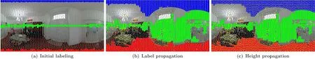
Fig.2 Image labeling and feature propagation.(a)Initialization of the labeling process,which assigns regions of the image to ceiling(blue),lf oor(red),wall(green)zones,leaving undecided areas as unknown.(b)Labeling after conservative propagation;we highlight super-pixels for which the height is known from the multi-view registration(yellow centroids).(c)Final propagated heights.
Given a superpixelSPklabelled as floor or ceiling,we define the facetFkto be the planar set of 3D points obtained by projecting the super-pixel using the following transformation:wherePloc∈Fkis the 3D position of the pixel(θ,γ)∈ SPk. The projection model is illustrated in Fig.3. The origin for these local Cartesian coordinates is the position of the spherical camera,while the abscissa and ordinate of the equirectangular image respectively represent the azimuthal angleθ and the tiltγof the view's direction,for a pixel(θ,γ)in the equirectangular image.Note that we do not assume that the whole vertical field is captured,but that we know how to map pixel coordinate to angles.Thus,we can cope with cameras that do not completely cover the vertical field(leaving uncaptured small top and bottom areas),assuming that the captured field is known.
In other words,a floor or ceiling facetFkis a horizontal patch corresponding to a specific superpixelSPk,parameterized by its heighthk.This representation has several advantages for identifying the underlying structure;indeed,the footprints of the floor and ceiling facets highlight the shape of the room(see Fig.3,right).
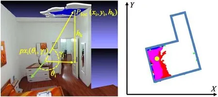
Fig.3 3D facets from super-pixels.Left:from a pixelpxi(θi,γi)(θandγ are angles relative to the direction of the image center,the green arrow)we obtain a pointPloc(xi,yi,hk)in world space using Eq.(2).As a result,super-pixel points generate horizontal facets in world space(here,blue ceiling facets).Right:labeled super-pixels from Fig.2 transformed to facets and projected on thex-yplane.Magenta zones represent the overlap between ceiling and floor projections,the yellow point is the camera position,and the azure contour is the underlying shape of the room.
This model assumes that labeled super-pixels to be transformed must have an associated height.Initially only those on which 3D features fall have one(see Fig.2(b)). In order to propagate heights to all labeled super-pixels,we adopt a push—pull[42]height propagation algorithm,assuming that there is at least one height coming from SfM in a connected labeled region(see Fig.2(c)).This ensures that,through the described propagation process,height values are assigned to all super-pixels in the floor and ceiling regions(Fig.2(c)),which by construction are both single connected regions.
The facets recovered from a single image do not generally suffice to define the shape of a room.In the next section we introduce an approach to efficiently combine these contributions to obtain a 3D floor plan.
6 Building 3D models by combining 3D facets from different images
Since we have a pose estimate for each camera,we can bring all estimated facet points to a common reference frame(see Fig.4)by computing their global locations asPworld=[RTi]-1Ploc,whereRTiis the transformation associated with camerai.We exploit this mapping by first subdividing the model into separate rooms(see Section 6.1),reconstructing the boundary of each room(see Secstions 6.2 and 6.3),and finally producing a merged 3D model(see Section 6.4).
6.1 Model partitioning
In order to subdivide the capture environment into separate rooms,we exploit a spatial reasoning approach,based on the occlusions between the pose track and the multi-view 3D points(Fig.5).As discussed in Section 5,the recovered features are too sparse for dense 3D point-based reconstruction,but they can provide enough information about strong occlusions along the path,such as a door or a narrowing.
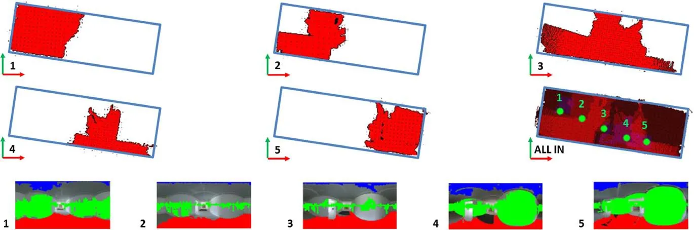
Fig.4 Facet combination(only floor facets are shown to simplify the illustration).1-5:Facets in five labeled images.All in:their accumulation array.Red shows facets labeled as floor,blue as ceiling,magenta as both ceiling and floor.Green dots show the camera positions.
To do this,we project the feature points and the camera poses onto the samex—yplane.We aggregate the feature points along LSD[43]segments(Fig.5,left),determining when such lines intersect the camera trajectory.We exploit such breaks to divide the poses into groups,also discarding images too close to the intersections(discarded images are not processed for shape recovery:see Table 1),since they most likely contain information that cannot be allocated unambiguously to one of the two parts.Once the images are assigned to a defined space,each room shape is recovered just analyzing only the belonging spheremaps(Fig.5,right).

Fig.5 Multi-room environment(D2 dataset;for simplicity we show only floor facets as background).Left:we arrange the images(positions in white)in different rooms by grouping them.We exploit 3D features(green dots)to estimate strong occlusions between poses(yellow lines)and breaks in the camera trajectory(blue segments).Poses too close to the occlusions are discarded(grey poses).Right:having grouped images,each room shape is recovered by projecting only the related images(3D reconstruction shown in Fig.11).
6.2 Room shape reconstruction
The 2D footprint of each room can in principle be extracted by finding in thex—yplane the bounding polygon of all 3D facets.To do so,we first find the room's 2D bounding rectangle from the projections of 3D facet positions,and then project the facets from the room images onto a regular grid,discretizing that bounding rectangle in order to obtain a footprint mask.The regular grid has a spacing of 4 cm in all experiments presented.Finding a regularized contour for such a mask provides the room boundary.
However,simply joining all facets from the different cameras associated with the room would only work if their generating super-pixels were perfectly segmented and classified.However,mainly due to poor indoor imagery quality and spherical distortion,several errors could affect labeling and height assignment,and,therefore,the facet's 3D position.
Figure 6 shows the effects of noisy super-pixel segmentation.Super-pixels inside the boxes(see Fig.6,left)have been wrongly labeled as floor(they actually belong to the walls),and consequently assigned an incorrect label,height value,and 3D position.
In the example shown,while the error occurs only in one image,the outcome affects the entire shape(see Fig.6,top right).
In our method,therefore,we propose a specific approach to join facets,to make the reconstruction more robust,outperforming competing solutions[4,7,8]with respect to noisy segmentation and untexturedregions.Since we have more than one labeled view for each part of the scene,we exploit this redundancy to assign a reliability score to each 3D point projected,and discard unreliable results.
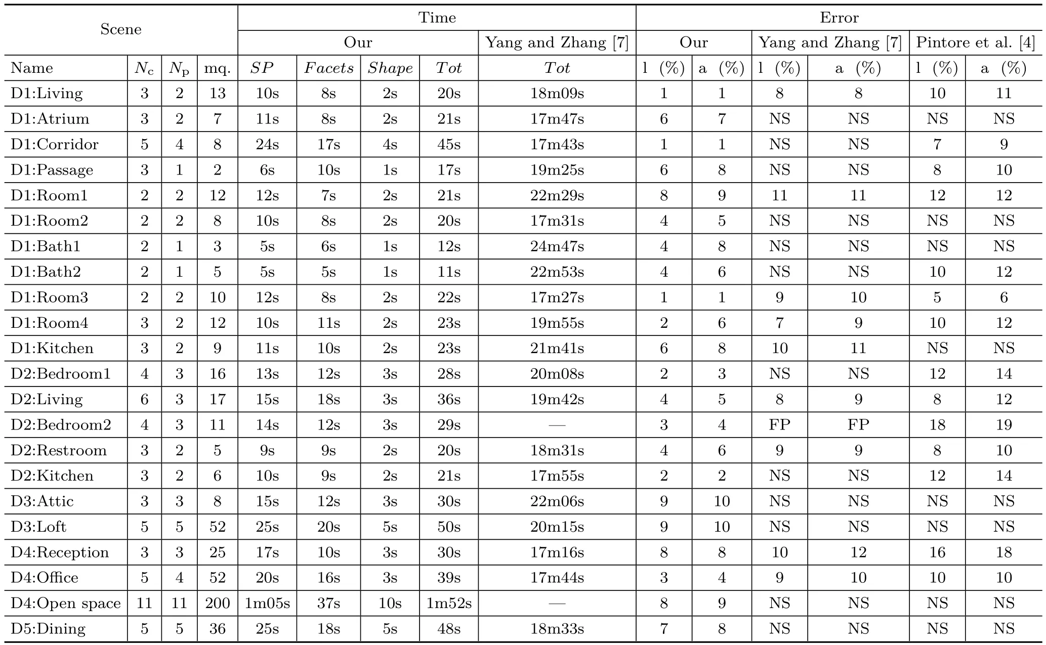
Table 1 Reconstruction performance for real-world multi-room environments,detailing results per room to allow comparison with single-view methods[4,7].Nc:total number of images captured,including passages and connections,Np:number of images processed to obtain the shape,followed by the room area.SP:time to compute super-pixels.Facets:time to create labeled facets.Shape:time to combine facets and find the shape in world space.Tot:total time to compute the room model with our method,and those of Yang and Zhang[7]and Pintore et al.[4].NS:no structure,i.e.,the reconstruction failed to return a model comparable to the real ground truth structure.FP:failed processing
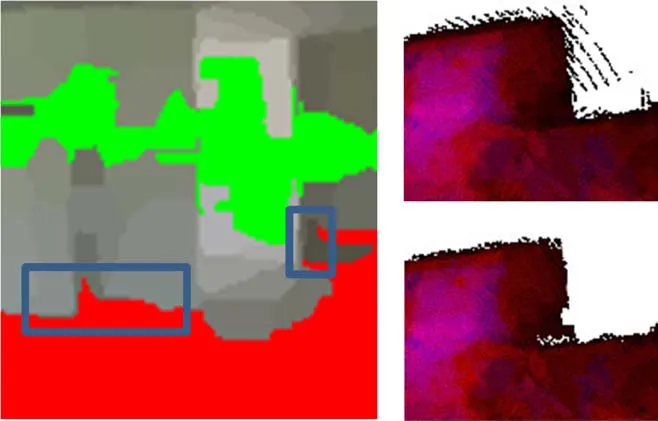
Fig.6 Incorrect classification filtering. Left:detail of some misclassified super-pixels.Top right:the effect of transforming superpixels without evaluating their reliability.Bottom right:overall results of merging the same area with our accumulation array(D4 dataset 7,grid size 4 cm).
In our approach,we project all 3D points from the ceiling and floor facets onto thex—ygrid,which we consider as an accumulation array instead of a simple Boolean mask.Each cell counts the occurrences at each labeled point,i.e.,how many images cover that cell with the same label.Furthermore,each cell can be at the same time covered by ceiling and floor facets.Including in each cell both ceiling and floor contributions,and filtering them by considering the distribution of multi-view contributions,make the room shape reconstruction more resilient against many clutter problems(e.g.,furniture covering the lf oor but not the ceiling).We evaluate the mean and the standard deviationσof the occurrences in the array,then we choose a threshold of 2σto remove less reliable cells(e.g.,see Fig.6,bottom right).We have experienced that about 96%of the values lie within the chosen threshold in all tests performed,and that cells with only one or two occurrences are usually discarded.De fining a small threshold for the minimum number of co-occurrences might therefore be an alternative viable alternative for filtering out spurious correspondences.
6.3 Room shape optimization
The final accumulation array provides a good approximation of the room boundary from which to extract the wall geometry.Since walls are vertical,their 2D footprints can be derived simply as the external boundary of the cells in the accumulation array that survive our filtering process.An obvious side effect of such an approach is that correct details can possibly be filtered out,e.g.,small peripheral parts of the structure that can hardly be seen,and labeled only from a single image.To compensate for this effect,and to eventually complete parts not labeled as ceiling or floor at all,we exploit in addition the data labeled as wall(see Section 5.1).
We exploit such wall contribution as 2D anchor points,in combination with the 2D shape recovered from the ceiling and floor footprint.First,we apply an iterative end-point fit algorithm[44](using 2%of the arc length as tolerance)to simplify the ceiling and floor footprint contour,obtaining a 2D polygon composed of line segmentsSk(,···,),and we initializeto this first polygonal approximation(see Fig.7,dotted yellow line).We then evaluate the initial distances of the wall anchor points to the Sksegments,in order to distribute a subset ofkof them(W0,···,Wk)as constant points,the closest point respectively to each segmentSk(,···,).Given the number of elementsWicountof each subset of points,fori ∈ [0,···,k],and representing the segments as a varying vector of 2kcorners(x0,y0,···,xk,yk)(so thats0andskdenote the same corner for a closed polygon),we formalize the optimization problem as
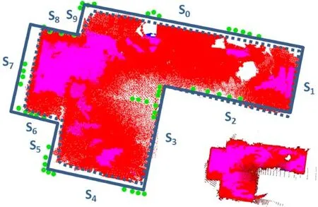
Fig.7 Shape optimization.We exploit the data labeled as wall to optimize the room shape.Differences and points are emphasized to illustrate the method(D4:open space room example,see Section 7).Bottom right:footprint shape before filtering(see Section 6.2).
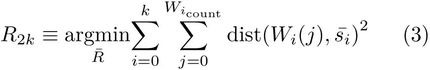
which,once expressed in matrix form,can be solved as a non-linear least squares problem with Levenberg—Marquardt iterations.
6.4 3D floor plan
Once the 2D shape of the indoor environment has been recovered,we exploit the 3D information contained in the closest facets to define a 3D model for each room.An example of a room with a sloping ceiling is illustrated in Fig.8.
In order to generate the 3D room shape from the recovered 2D footprint,we identify the ceiling and floor facet candidates for providing heights.These candidates are found by extracting the ceiling and floor facets whose projection on thex—yplane overlaps a wall segment.Once we have identified the candidate facets,we exploit their heights to generate for each 2D corner a 3D edge formed by two 3D points(e.g.,in Fig.8,we selecth0from floor facets andh1from ceiling facets).Then,in order to consider any intermediate variations in wall heights between original corners(e.g.,as in Fig.8 with a doublysloped ceiling),we check the height information of the candidate facets against each wall segment,inserting,in the case of significant variations,new vertices in the ceiling 3D shape(e.g.,in Fig.8,P4andP7).We use a greedy method that iteratively inserts a new vertex when the maximum difference in height between the current shape and the shape including the vertex is larger than 10 cm.The vertices are scanned in order of decreasing error.
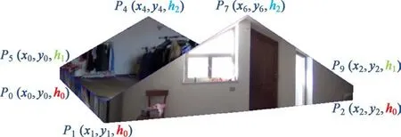
Fig.8 3D room generation.We exploit the 3D information contained in facets closest to the recovered 2D shape to generate the 3D points.In the sloping ceiling case illustrated(D3-Loft)3 height levelsh0,h1,h2have been recovered and associated with 3D vertices.Note that the windows and doors are actually sloping in this particular room.
The approach can return a 3D reconstruction even for non-trivial space arrangements,large occlusions,and sloped ceilings,assuming that some height levels are detected,even sparsely,by the SfM pipeline.This is typically the case in practice,since the edge between ceiling and wall often leads to the presence of image features.
7 Results
To demonstrate our approach,we developed a reconstruction pipeline that,starting from a collection of spherical images and their multi-view alignment,automatically produces a structured 3D floor plan in terms of interconnected rooms bounded by walls.This system has been implemented in C++on top of OpenCV.To obtain camera registration we developed a tool based on the approach of Kangni and Laganiere[40]. Other available tools,such as PhotoScan(http://www.agisoft.com/),could also be used for this purpose.
7.1 Data collection
We evaluated our approach by capturing real-world environments.We created ground truth data from on-site inspection aided by laser measures,comparing these to available blue prints.
We included in our results common indoor scenes,which typically have non-diffuse and homogeneous surfaces.In such typical indoor environments,the lack of 3D information from structure from motion and multi-view stereo(see Fig.13)makes those approaches based on direct point-cloud analysis hardly practicable[8].Furthermore,as the algorithm is explicitly designed to work with partial visibility of cluttered environments,we present results for cluttered scenes(see Fig.9).
We captured equirectangular images,covering a full viewport of 360°longitude and 180°latitude,with a resolution of 5376×2688,using a commodity Ricoh Theta S spherical camera(https://theta360.com/en/about/theta/).To maximize the bottom hemisphere coverage,we mounted the camera on a tripod,at a fixed distance of 170 cm from the floor,and exploited this information to obtain final models with real-world metric dimensions,thus allowing a direct comparison with ground truth.To recover the camera poses and multi-view features,we acquired images with a suitable overlap,usually capturing at least two images for each room,with a maximum distance of 6 m between them.We make all datasets available to allow further studies and comparisons.The acquisition time was under 20 minutes for each multi-room environment.All reconstruction tests were performed on an Intel i7 processor with 16 GB RAM.
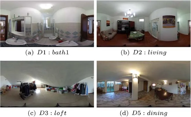
Fig.9 Captured panoramic images.We have captured many cases with textureless walls and ceilings,as well as moderately to heavily cluttered environments.Such clutter is not evident in the reconstructed 3D models,which include only the geometric boundary data and not the removed clutter.
7.2 Room shape reconstruction performance
We present quantitative performance data for our method in Table 1,detailing results for each room,contextually showing limitations of singleview approaches that also use similar geometric reasoning[4,7].To provide this comparison,we choose,among the captured poses of each room,the best view captured in terms of space coverage(i.e.,with the maximum number of visible corners).
The Scene field in Table 1 shows the number of captured poses for each roomNc,which also includes the poses exploited just to track the multiview features(e.g.,in the middle of a door)but not processed for shape extraction,and the number Npof poses actually employed for reconstruction(see Section 6.4).We also indicate the room area in square meters.The SP field shows the processing time needed to cluster,label and propagate the classification of about 2048 super-pixels(i.e.,for an image scaled by 4 with respect to its original size)for Npimages.The Facets field reports the time needed to create each room's facets.This includes the time to registerNcimages(including a proportion of the global bundle adjustment time)and the time to create the labeled facets fromNpimages.The number of captured and processed images increases with spatial dimensions,and,above all,with the complexity of the environment(so e.g.,a U-shaped room requires more images than a box-like room).The Shape field gives the time needed to create the accumulation array from theNpimages and to recover the 3D shape.The Tot column summarizes the total time required to automatically generate a room with our method.For comparison,we also give the time required to infer a 3D room layout with the single-view approach of Yang and Zhang[7](CVPR2016 code snapshot:https://github.com/YANG-H/Panoramix).Reported time includes preprocessing(which was not indicated in their paper)and the actual time to infer the room layout(about one minute for every room).The comparison shows that the time required by our method to find the room structure from multiple images is significantly lower than the time required by this other approach to process a single image(seconds versus minutes).The Error field indicates the maximum percentage error based on ground truth for wall length and room area,and for the structures recovered with the comparable methods of Pintore et al.[4],and Yang and Zhang[7],once their results have been manually scaled to metric dimensions.It should be noted that,unlike our approach and the approach of Pintore et al.[4],the method of Yang and Zhang[7]is targeted to provide an up-to-scale and cluttered 3D sketch of an indoor panorama,and not the underlying room structure as conceived in a floor plan.For the sake of clarity we compare numerical values of their method only when their reconstruction provides a comparable footprint of the room.
Numerical results confirm that,even for individual rooms,combining color analysis with multi-view clues is more effective than inferring the whole reconstruction from image segmentation and gradient analysis.As we expected,our approach returns a reliable reconstruction also when the other approaches fail to find the room structure,such as in presence of hidden corners(see D1:Atrium,D1:Room2),large clutter(see D1:Kitchen,D2:Bedroom1,D3:Lounge),sloping ceilings(see D3:Attic,D3:Loft)or complex environments containing several of these issues at once(see D4:Open space).The scenes with sloping ceilings highlight the ability of our system to handle scenes with different height levels,unlike many other approaches[4,7,8,39].In our results we measured height errors between 6 and 13 cm in Figs.10 and 12(c),and height errors ranging from 8 to 25 cm in the case of double pitched roofs illustrated in Figs.8 and 12(e).In both cases we found the largest error on the wall with more clutter.
7.3 Multi-room performance
Most of the benefits of our method arise in its use in multiple and structured environments and,in general,where single-view approaches are ineffective or less reliable.In terms of multi-room structure extraction,our method is comparable with the method of Pintore et al.[4],which is closest to ours,although limited by many more assumptions,amongst which is a single image per room.We exploit for reconstruction the code provided by the authors[4],adapting their door matching approach to use a spherical panoramic camera(the original being based on panoramic stitching).In Fig.11 we compare reconstructed floorplans against real and metrically scaled ground truth(background layer).We also show the 3D floor plans as textured models.Performance is summarized in Table 1,detailing results for each room to provide further comparison with single-image state-of-the-art approaches(i.e.,Ref.[7]).It should be noted that metrics such as pixel classification error(proportion of pixels that disagree with the ground-truth label)are inapplicable to our method since our goal is to recover the underlying structure,exploiting parts of many images,which clearly cannot be remapped onto the original images and their clutter.
Fig.10 Height distribution,for a room with a sloping ceiling(D3-Attic).
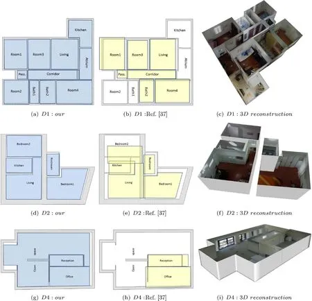
Fig.11 Recovered footprint and 3D models versus ground truth floor plan.Grey footprint:real,metrically scaled,ground truth.Left:results of our method.Center:results from the multi-room approach of Pintore et al.[4].Right:our final textured 3D floor plan.Ceilings and septal wall have been removed from the 3D reconstruction to assist viewing.
The first row shows reconstruction of a typical apartment layout(the D1 dataset).As each room has a fairly regular structure,the main challenges are the splitting of spaces(eleven rooms)and the clutter.Our method(see Fig.11(a))returns almost perfect spatial mapping and shape for each room,with an overall area error relative to the ground truth footprint,including wall thicknesses,of about 5%.In Fig.11(b)we show the same environment reconstructed with the approach of Pintore et al.[4]where,mainly because of clutter,the reconstruction of some rooms fails(i.e.,the method does not return a measurable reconstruction).Furthermore,as rooms are joined by matching doors,considerable mapping errors are present.In the second row we present a different kind of structure,a residential environment situated within the walls of an old building,characterized by non-Manhattan world corners and very thick walls(the D2 dataset).As our method performs even better than in the previous case,both in terms of mapping and area error(overall area error is 4%),while other approaches again result in higher area errors(17%)and inaccurate mapping,due to presence of very thick walls(65 cm).The third case is a larger,complex structure,where an office layout has been created in a former factory.This layout is arranged in 3 functional spaces(reception,office,open space)across 290 m2(the D4 dataset).In particular,the open space is distributed around the central reception and a septal wall,describing a U-shape which cannot be captured with only one view.Moreover,the presence of large areas of homogeneous color and large windows makes this structure hard to recover with a dense method(see Fig.13).Again in this case,our method returns a reliable reconstruction(see Fig.11(g))with a very low error,8%,especially considering the large size and peculiar topology.On the other hand,the approach used for comparison expects rooms in which all corners are visible from a single viewpoint,so fails to reconstruct the main room(see Fig.11(h)).
It should be noted that,in contrast to approaches that need an adequate number of 3D points to determine room shapes[8],our method can effectively work on texture-poor environments,including those presented.As we use SfM essentially for determining camera pose,after that our method works even if there is just a single 3D point per room in the case of a horizontal ceiling and floor,and we only need a few more in the presence of sloping ceilings.
7.4 Qualitative comparison
Figure 12 gives qualitative performances of our method for some cases where single-view approaches are unable to recover the underlying room structure(marked NS in Table 1),and a visual comparison with the output of the pipeline of Yang and Zhang[7](a visual comparison with the method of Pintore et al.[4]was presented for the multi-room case in Fig.11).Figure 12(a)shows a room with non-Manhattan world corners,large clutter,and a mirror on the wall.While our method correctly recovers the room shape,the other approach misses many of the room's walls,which are occluded by the wardrobe,as well as reconstructing wrong parts in the presence of a bed(the diagonal lines motif between wall and floor leads to incorrect estimation of vanishing lines),a mirror and an open door.Figures 12(c)and 12(e)show our reconstruction for singly-and doubly-sloping ceiling environments.Incomplete reconstructions shown in Figs.12(d)and 12(f),instead,highlight one of the most critical points of the single-view approaches applied to spherical images,namely the way in which lines are extracted to provide a geometric context.In an equirectangular projection,in fact,lines are not usually directly detectable(except for the vertical ones),but arbitrary perspective projections are generated to find them in an undistorted space[45],and these detected lines are then transformed back to the original space. This approach works very efficiently for lines close to Manhattan world directions[46],but tends to fail for less conventional directions,like some in the examples given. Figures 12(h)and 12(j)show the reconstructions obtained from a single viewpoint compared with ours(Figs.12(g)and 12(i)),both having problems due to clutter.In addition,Figs.12(b)and 12(h)highlight misclassification problems discussed in Section 6.2.We show instead in the last comparison(Fig.12(k)versus Fig.12(l))a case in which the single-view approach does return a reliable structural reconstruction.
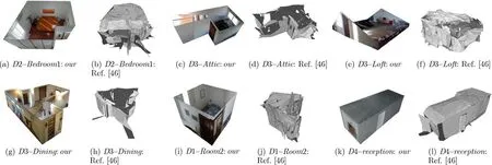
Fig.12 Single room environments where single-view approaches tend to fail.Besides our reconstructions,we give the output of a single-view approach[7]for some cases marked NS(no structure)in Table 1.The last pair shows our reconstruction(k)and that of Ref.[7](l)on a case where both work.
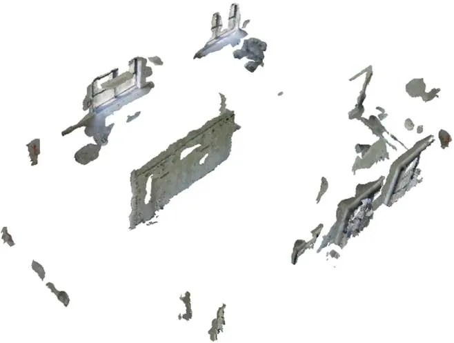
Fig.13 Reconstruction from the point cloud only,showing the output of a dense multi-view pipeline(PhotoScan)applied to the D4 dataset.Mesh extraction and tiled model recovery have been also applied to enhance the illustration.
For completeness,in Fig.13 we show the output of a standard dense multi-view pipeline,applied to the same data reconstructed by our method in Fig.11.Reconstruction was performed using PhotoScan on the original panoramic images,carrying out camera alignment and point cloud densification.As shown by the examples,such reconstructions contain several sparse details of interior clutter,but lack structural parts of the rooms(typically,all ceilings and external walls).Methods that derive the structure from a point cloud are unworkable[8,12].
Asto limitations,ourmethod targetsthe reconstruction of indoor environments in terms of rooms bounded by walls,ceilings,and floors.We do not,thus,handle the reconstruction of furniture or additional architectural elements such as stairs.This is because the method is explicitly only intended to reconstruct the bounding volumes of rooms,together with multi-room connections.
We do not make the Manhattan world assumption[47]that vertical planes are orthogonal to each other,so we can also handle sloped ceilings.We only assume that walls are vertical.
For the reconstruction to be successful(see Section 5.2),our method requires that there is at least one height available from SfM in a connected labeled region,in order to automatically recover the ceiling height.In the case of sloping ceilings we must have enough features to reconstruct the slope.While curved vertical walls can,in principle,be handled if enough features are present to define their 2D footprints,obtaining them is often a problem in practice,and often leads to failures(see Fig.14),although in future the approach could be extended to better deal with these cases.
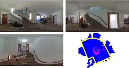
Fig.14 A failure:a scene with open ceiling,stairs,and a curved wall where our method failed to recover the structure.We show some of the original captured images,the resulting incorrect transform in the 2D plane,and the expected real shape(yellow).
Since many indoor scenes,especially in office and apartment buildings,meet our method's assumptions[48],the above limitations can be considered acceptable.
8 Conclusions
We have presented a novel and practical approach for recovering 3D indoor structures using low-cost 360°cameras. Our work has introduced several improvementsoverpriorapproachesaimedat extracting structural information without requiring dense data capture.In particular,our framework based on 3D facets combines a new approach for geometric context extraction,with a new technique for combining facets from different points of view into a single consistent 3D model,without strictly imposing Manhattan world constraints.As illustrated by our results,only a few overlapping images are required to generate a 3D floor plan,even when other previous approaches fail,such as in presence of hidden corners,strong clutter,and complex multiroom structures.
We envision,as future work,to extend the mixing of single-view and multi-view labeling to extract other structural information from the data,such as clutter in rooms,in order to create a complete furnished 3D model.
Acknowledgements
This work was partially supported by projects VIGEC and 3DCLOUDPRO.The authors also acknowledge the contribution of the Sardinian Regional Authorities.
杂志排行

Computational Visual Media的其它文章
- DeepPrimitive:Image decomposition by layered primitive detection
- Resolving display shape dependence issues on tabletops
- FLIC:Fast linear iterative clustering with active search
- Acquiring non-parametric scattering phase function from a single image
- Deforming generalized cylinders without self-intersection by means of a parametric center curve
- FusionMLS:Highly dynamic 3D reconstruction with consumergrade RGB-D cameras