Design and experiment of inclined inserted no-tillage hill seeder
2017-12-20LinYuexiangShangShuqiWangDongweiCuiZhenchaoYangHongguang
Lin Yuexiang, Shang Shuqi※, Wang Dongwei, Cui Zhenchao, Yang Hongguang
Design and experiment of inclined inserted no-tillage hill seeder
Lin Yuexiang1, Shang Shuqi1※, Wang Dongwei1, Cui Zhenchao2, Yang Hongguang1
(1.266109,; 2.o 266061,)
The purpose of conservation tillage is to protect soil structure, conserve water and maintain soil moisture. No-tillage sowing is the core of the development of conservation tillage technology. Focusing on many problems unsolved of no-tillage planter, such as the non-adjustable space between seeds, seeding only on a single line, high probability to be adhered and blocked, and poor adaptability, this paper proposes a new advanced design of no-tillage hill seeder. The hill seeder is connected to tractor with the suspension frame, and it can complete a seeding of three rows by three planting units at every run. Each planting unit is mainly composed of land wheel, seed metering device, fertilizer apparatus and 45° inclined inserted digging implement. The digging implement is mainly composed of parallel four-bar mechanism, slider-crank mechanism and cam mechanism. The power transmission route is as follows: the land wheel rotates to obtain power, drives the seed metering device and fertilizer apparatus, and then through the chain drive to the parallel four-bar mechanism and slider-crank mechanism, completing penetration reciprocating seeding and fertilizer, while driving cam mechanism controls the opening and closing movement of the duckbill. The design of no-tillage hill seeder has the following features. Firstly, to efficiently avoid the problems of soil blocking, soil attaching, difficulties in opening and so on, this new hill seeder would perform an insertion into soil at a 45°angle with a refined plugging unit. Secondly, this design has added configurable sprocket gears to solve the problem that the existing seeders could not adjust the distance between seeds. Thirdly, the design of the parallel four-bar mechanism makes the insertion of the crank blocks more smoothly with the unifiedseeding depths, at the same time the synchronization of seeding and fertilizer could be achieved. Additionally, all the parameters of the machine (e.g. rows spacing, plants spacing, seeding depth, fertilizer depth) are adjustable which could bring better adaptability. Field experiment was done in the experiment base by inclined inserted no-tillage hill seeder prototype. The results showed that seeding depth and fertilizer depth qualified rates were 90.52% and 91.23%, qualified rates of horizontal distance and vertical distance between seed and fertilizer were 95.71% and 91.65%, qualified rate of seeding uniformity is 92.13%, replay rate of seeding uniformity is 4.60% and leakage rate of seeding uniformity is 3.27%. The data are superior to the standard value, which is 85%, 15% and 8%.The research can provide a reference for the design of no-tillage planter.
agricultural machinery; design; experiments; no-tillage; hill drop seeder; cell wheels; digging implement
0 引 言
China’s water resources per capita are only a quarter of the world’s average[1-5], which directly affects the irrigation of the arable land and seriously restricts the development of agricultural economy[6-8].Conservation tillage can effectively improve soil storage and moisture retention ability. It focuses on retaining stubble coverage, reasonable crop rotation, rational fertilizer and pesticides and other measures in order to provide an appropriate growth environment for crops to achieve the goal of high yield, low consumption, and decreases of soil erosion[9-13]. The key application of conservation tillage technology is the research and development of no-tillage seeder.
At present, no-tillage seeder has a pretty large market abroad, which is able to break stubble, open ditch, sow, fertilize and pesticide at the same time. The seeders abroad are usually heavy and in large size while equipped with complex soil working components[14]. As we know, no- tillage seeders of KMC, USDA and John-Deer are all well designed and practically useful, however, situations such as land size, soil quality, economic level and so on are totally different in China. Therefore, the foreign no-tillage seeders do not fit in China.
Research of no-tillage seeder started relatively late in China. In recent years, the research has made certain achievements and a variety of no-tillage hill seeders have been developed, such as 2BFY-6 corn no-tillage fertilizing seeder, 2BMJF-4C tooth type pulling weeds corn no-tillage seeder and 2BFY-3A2 corn fertilizing seeder, etc. Experts and scholars have studied and improved the key components of no-tillage planter, which are mainly used in maize and wheat seeding[15-19]. However, no-tillage seeder is still not widely used at present, for the opener structure could not fundamentally solve the congestion problem and the digging mechanism need to be improved.
In this paper, a new type of no-tillage planter is developed, which can be adjusted spacing and seeding depth to meet the needs of different species. Seeding and fertilization work can be completed at one time.
1 Scheme design of inclined inserted no-tillage hill seeder
1.1 General structure
To resolve the existing problems of hill seeder, a inclined inserted no-tillage seeder is designed, the whole structure is shown in fig.1a.
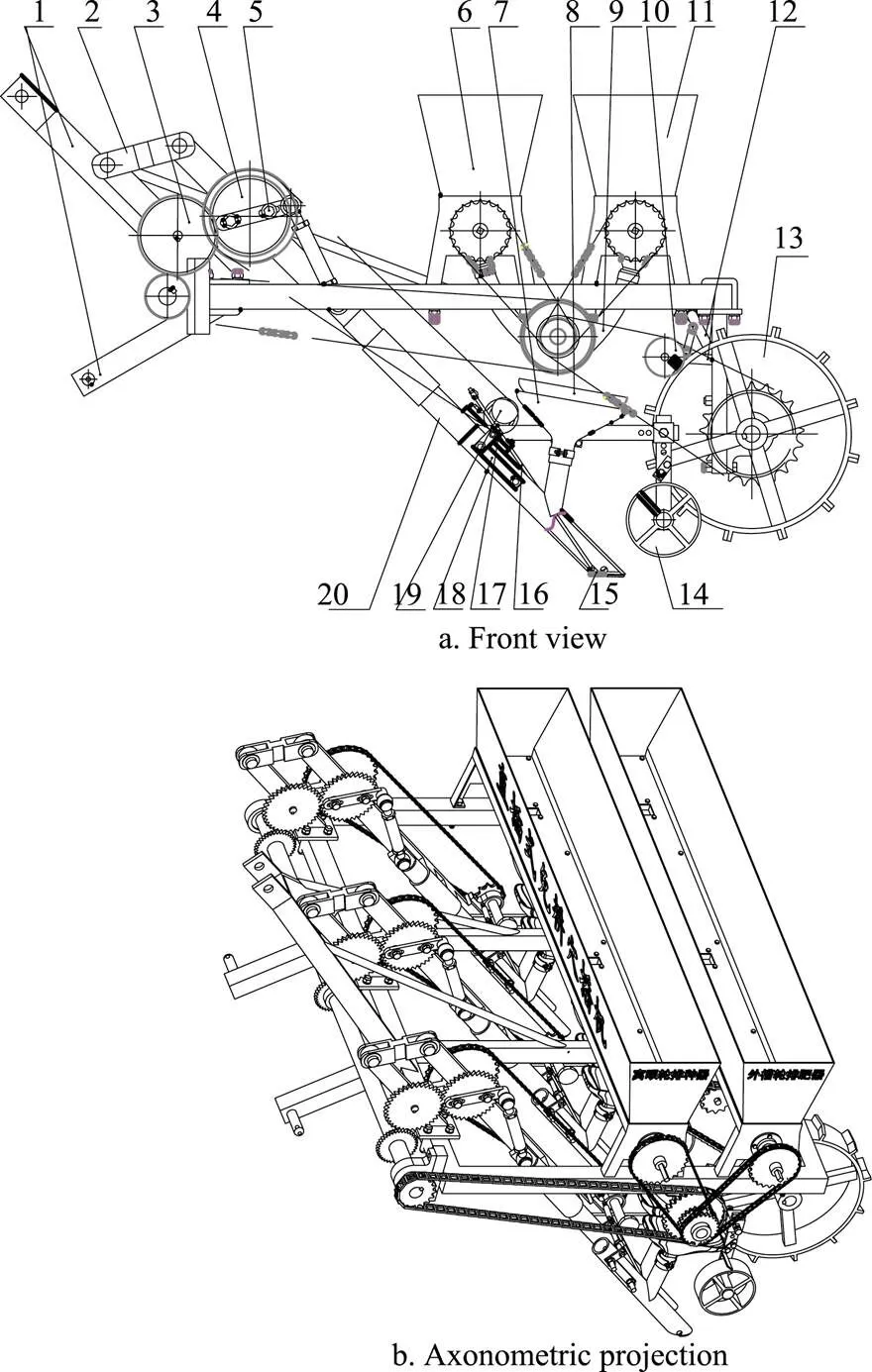
1. Suspension bracket 2. Profiling connecting rod 3. Intermediate gear 4. Big gear 5. Crank adjustment bolt 6. Seed box 7. Fertilizer bucket 8. Seed bucket 9. Delivery pipe 10. Tension wheel 11. Fertilizer box 12. Tension wheel rack 13. Land wheel 14. Profiling wheel 15. Flexible duckbill 16. Pull rod rack 17. Pull rod guide bushing 18. Pull rod bracket 19. Cam 20. Digging mechanism
The seeder adopts suspension structure with wheeled tractor to support power. Working parts of the seeder mainly include frame, power transmission mechanism, 45° inclined inserted digging implement assembly, fluted roller fertilizer apparatus and seeding device of socket-roller, etc.
Tractor drives land wheel rotation to drive the metering device and the fertilizer device and parallel four bar mechanism, slider crank mechanism by chain drive, complete the reciprocating motion into and out of the soil while driving cam controls the duckbill to complete seeding and fertilization action.
1.2 Main technical parameters
According to the seeding agronomic condition and existing standards, the main technical parameters of the hill seeder are shown in table1.
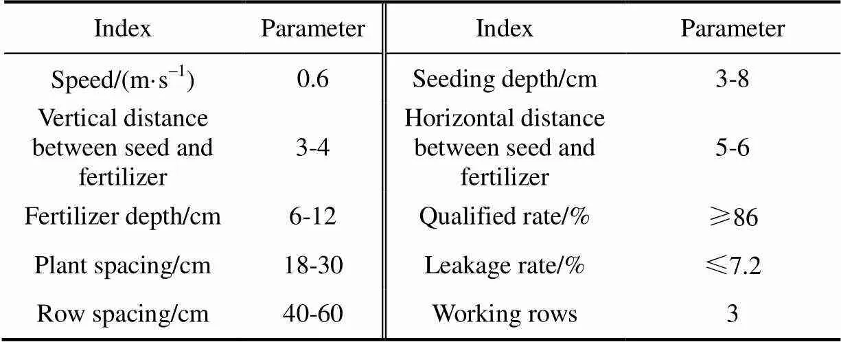
Table 1 Main parameters of inclined inserted no-tillage seeder
2 Design of key parts
2.1 Structure of 45° inclined inserted digging implement
The 45° inclined inserted digging implement is mainly composed of three major components: parallel four-bar mechanism, slider-crank mechanism and cam mechanism (as shown in fig. 2).

1. Pins 2. Digging implement sprocket 3. Transmission chain 4. Moving frame 5. Digging pipe guide sleeve 6. Bearing block 7. Bearing 8. Seed bucket 9. Fertilizer bucket 10. Seeding tube 11. Fertilizer tube 12. Profiling wheel adjustment block 13. Scraper plate 14. Profiling wheel bracket 15. Profiling wheel 16. Flexible duckbill screw 17. Flexible duckbill 18. Fixing clip for seed and fertilizer bucket 19. Pull rod 20. Series bolts 21. Pull rod pull-off spring 22. Pull rod bracket 23. Cam 24. Cam shaft 25. Pull rod guide bush 26. Pull rod linkage device 27. Digging pipe shaft 28. Lock nut for connecting rod 29. U-bolt 30. Adjustable connecting rod 31. Adjustable crank 32. Crank fixed bolt 33. Crank shaft 34. Intermediate gear 35. Intermediate gear shaft 36. Fixed frame 37. Profiling connecting rod
Parallel four-bar mechanism is mainly composed of moving frame 4, fixed frame 36 and two profiling connecting rods 37. Fixed frame is fixed on the rack by U-bolts 29, the up-profiling rod respectively hinged with the moving frame and fixed frame by pin shaft, the down-profiling rod respectively hinged with moving frame and fixed frame by shaft sleeve. Interference fit is used between the sleeve and the frame. The sleeve is clearance fit with down-profiling linkage.Digging pipe guide sleeve, pedestal and the profiling wheel bracket are all fixed on the moving frame.
Slider-crank mechanism is mainly composed of adjustable crank, connecting rod and digging pipe. The digging pipe consists of seeding tube and fertilizer tube, both tube nozzles are of 45° wedgeshape. The two tubes are strung together by two bolts. A cushion is placed between the two tubes, by controlling the thickness of which can adjust the lateral distance between fertilizer and seed.
Digging pipe insert into the guide sleeve, which constitutes slider-crank mechanism with adjustable crank and connecting rod. The adjustable crank has two long slots, which are fixed on the gear by the fixed bolt of the crank, and the length of the crank can be adjusted by changing the position of the bolt in the slot. Adjustable connecting rod is articulated with the digging pipe axis and crank shaft pin, with screw threads and lock nut on both ends, so that the length of connecting rod can be changed by adjusting the screw depth.
The cam mechanism is mainly composed of flexible duckbill, pull rod, return spring of pull rod, pull rod sleeve, pull rod linkage, cam, cam shaft and small sprocket, etc. The flexible duckbill covers the digging pipe nozzle to keep soil out.The inner edge of the flexible duckbill is smaller than that of the nozzle, which can be embedded in the tube, and the outer edge is larger than the pipe nozzle, which can cover the nozzle. This structure has a good sealing effect that the flexible duckbill is automatically pressed on the pipe under the pressure of soil, so it can work with no external force. The end of flexible duckbill is articulated with pull rod that extending from the opening of digging pipe and articulated with pull rod linkage by the return spring and rod sleeve. The pull rod linkage makes the two rods can be lifted by the cam. The pull rod linkage has a sleeve, the inner side of the sleeve is made of steel pipe to reduce friction, and the outer sleeve is provided with rubber sleeve to prevent slipping with the cam. The cam is fixed at one end of the camshaft, and the small sprocket is fixed at the other end of the camshaft. The power is obtained from the upper sprocket by the drive chain.
2.2 Working principle of the digging implement
The moving frame of inclined inserted digging implement moves along with the seeder, and the profiling wheel on the moving frame does profiling movement along the ground surface. The crank, connecting rod and digging pipe are all fixed on the moving frame and do identical movement to ensure seeding depth in consistent. When working, power provided by land wheels is conveyed to the intermediate gear that rotates clockwise, the digging pipe is reciprocating under the action of slider-crank mechanism, and insert leaning back into soil with the angle of 45°. As the planter goes forward, the digging pipe is inserted once every distance forward. The range of reciprocating motion can be changed by adjusting the length of crank, and the embedded depth can be controlled by changing the length of connecting rod. The fertilizer pipe is in parallel connection with the seeding pipe, both of them insert into the soil at the same time, and there is a horizontal interval is 6 cm between them (that can be adjusted by the thickness of the block), and fertilizer pipe is 3-4 cm lower than the seeding pipe to meet the best fertilizer placement[20-23]. The crank-slider mechanism is a center-crank slider. When the crank is collinear with the axis of the digging pipe, the crank has reached the extreme position, the lower limit position is the seeding depth. The crank continues to rotate, digging pipe begin to ascend, push rod cam linkage and drive two bar inclined upward and traction activities nozzle rotation, seeding and fertilizer tube are opened for seeding and fertilizer. At the end of the cam push, the digging pipe continues to rise, the rod linkage moves away from the working range of the cam, and the pull rod is rapidly back under the action of the pull rod return spring, so as to push the movable nozzle to rotate reversely until the nozzle is tightly sealed. Because of the timely action of return spring, the top of the flexible duckbill is blocked by nozzle, and the inner of flexible duckbill is smaller than the pipe, the mechanism can effectively prevents clip soil and congestion issues. The digging pipe continues to rise, the seeding pipe and the fertilizer pipe are drawn out from the soil, and the soil is covered by the profiling wheel as the seeder moves forward. When the seed manure bucket rises with the digging pipe approaching the seeding pipe and the fertilizer pipe, seed and fertilizer falls and be caught respectively by their bucket, finally falls to the bottom of the pipe, and blocked by flexible duckbill to wait for the next seeding. So far, a work cycle has been completed[24-26].
The cell wheel of cell wheel seed metering device is divided into four sections along the axial direction, and the holes of different sizes are evenly distributed along the circumference of the different segments. The axial position can be adapted to the seeding of different crop seeds.
2.3 Design and calculation of slider-crank mechanism
The slider-crank mechanism is shown in figure 3.
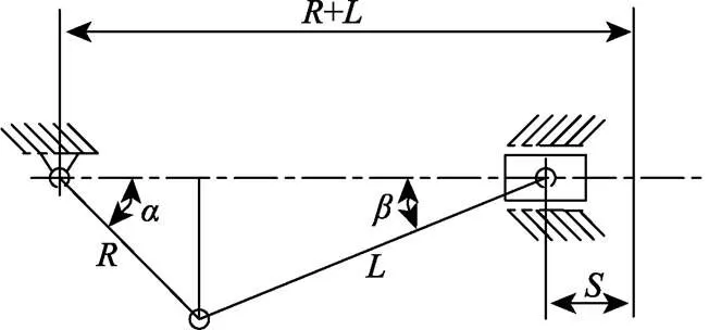
Note:ais the angle between crank and slider motion line, (°); b is the angle between connecting rod and slider motion line, (°); S is the displacement of digging tube, mm; R is the length of crank, mm; L is the length of connecting rod, mm. The same below.
2.3.1 The calculation of soil resistance
The soil resistance is divided into friction resistance(1) and cutting resistance(2). The formula for calculation is as follows:

Whereis friction coefficient of steel in soil,the value range ofis between 0.577 and 0.721, select theas 0.7; N is positive pressure of digging pipe, N;is specific gravity of soil,=2.65 mg/m3;0isdepth to soil of digging pipe,0=4 cm;is thediameter of digging pipe,=5 cm;1is maximum movement distance of digging pipe,1=0.11 cm;is maximum specific resistance of soil,=24 000 N/m3;is contact area between the digging pipe and soil, m3.
Therefore, soil resistance is=1+2=60 N.
2.3.2 Design and calculation of slider-crank mechanism
Displacement of the digging pipe[27]is:

Instantaneous velocity of the digging pipe is:

Instantaneous acceleration of the digging pipe is:


The calculation result shows that the torque of crank shaft (1) is a function of the independent variables with soil resistance (), angle of pressure (), crank length () and the length of the connecting rod (). According to the actual situation of the hill seeder, taking=60 N,max=66°,90 mm,220 mm, the maximum torque required on the crank shaft is obtained. That ismax≈6.57 N·m.
2.4 Design and calculation of cam mechanism
On one end of the camshaft, a driven sprocket is connected with the driven sprocket through a chain, and the driven sprocket rotates coaxially with the big gear. When the digging pipe moves to bottom, that position is the cam’s inactivity position, when it continues to rise, the cam gets into pushing course, promoting the linkage device to make flexible duckbill open, if the mouth needs to open quickly, the camshaft speed must be faster, the master-slave motion sprocket ratio of the digging device is 1/3, if the seeding row distance is 18 cm, the camshaft speed is 600 r/min[28-30].

Note: P is soil resistance, N; PAB is pressure of connecting rod, N; ω is angular velocity of crank, rad/s; N is pressure of slider, N; M1 istorque of connecting rod, N·mm.
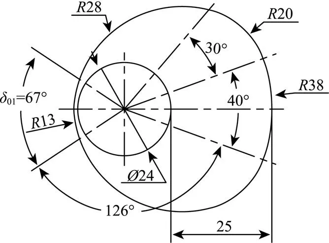
Fig.5 Contour curve of cam
By calculation when the flexible duckbill opens to the maximum, the linkage device needs to be pushed 9 mm. Therefore, push process:1=25 mm.
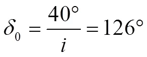
Because of the camshaft rotating speed is faster than the crank shaft, when the digging pipe has just left the deepest position, if the flexible duckbill opens immediately, it will push the soil at the bottom, which will increase the load of the cam opening and closing mechanism, which will cause great harm to the mechanism, so it is necessary to avoid the flexible duckbill to promote the soil. As a result of that, we designed a larger close angle:01=67°.
When the cam rotates over the pushing path, the linkage device moves up follow the digging pipe, at the same time, the cam is no longer working, so, there is no requirement for the far reposeangle and return angle of the cam. But for the sake of easy manufacturing, this cam mechanismuses the symmetrical structure, on the basis of calculated return angle0′and far reposeangle02′:
0′=0=126°
02=40°
2.5 Motion state simulation of digging implement
Pro/Engineering 5.0 is used to simulate the motion of 45° inclined inserted digging implementto test the coordination of movements, as shown in Fig.6.The initial position of digging implement is inserted into soil, and the forward speed is 0.6 m/s.
1-2-3shows that the flexible duckbill is opened for seeding and fertilizer under the action of the cam.4-5-6shows the flexible duckbill closing process under the action of the spring pressure.
The simulation results showed that the coordination of digging implement is good, and the seeding and fertilizer action can be completed well.
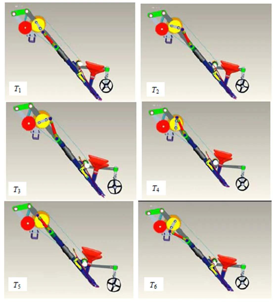
Note:T1-T3 : the duckbill is opened for sowing and fertilizing under the action of the cam; T4-T6 : process of pushing the liver back and closing the duckbill under the action of spring.
3 Design of the transmission institution
As shown in fig. 7, three groups digging mechanism are installed on the frame. The walking device is composed of land wheel, axle and wheel frame, etc. Speed adjusting drive chain wheel on the camshaft connects with driven wheel on the intermediate shaft by the land wheel chain. The hill seeder transmission is made up of chain and gear transmission, the transmission ratio is stable. The seed distance can be adjusted by changing the transmission ratio. Therefore, the wheel speed-adjusting mechanism is added to change the chain position. In this way, we can make two wheels work with different transmission ratio to change the planting distance.
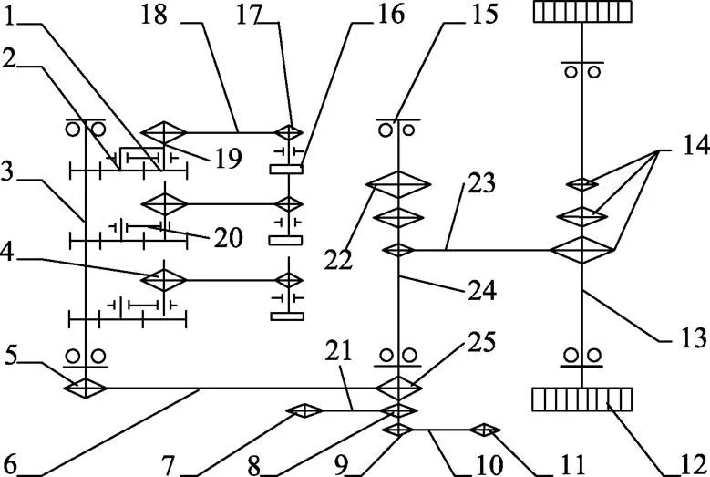
1. Big gear 2. Intermediate gear 3. Spindle 4. Camshaft drive sprocket 5. Small sprocket 6. Main shaft transmission chain 7. Metering driven sprocket 8. Metering drive sprocket 9. Spindle bearing seat of fertilizer device drive chain wheel 10. Fertilizer device chain 11. Driven sprocket of fertilizer device 12. Land wheel 13. Land wheel shaft 14. Speed adjusting drive sprocket 1 15. Bearing 16. Cam shaft 17. Camshaft driven sprocket 18. Camshaft chains 19. Crank shaft 20. Profiling connecting rod 21. Metering device chain 22. Speed adjusting drive sprocket 2 23. Chain of land wheel 24. Intermediate shaft 25. Big sprocket
4 Experiment and analysis
4.1 Experiment conditions
Operating performance test of inclined inserted no-tillage hill seeder was taken in Pingdu experimental base at Qingdao Agricultural University on June 10, 2015. The experimental base is located in the southeast coast of Shandong Province. It is a warm temperate and semi-humid continental monsoon climate. Test site implements no-tillage seeding. Soil type of the experimental base is brunisolic soil, and average soil water content is 12.9%. The length of tested area is about 110 m and width of that is 43 m. Taishan 354-H tractor was used as supporting power. According to the climate conditions, Denghai 3622 was chosen as test corn seeds, its 100 grain weight is 30.2 g.
4.2 Experiment methods
Experiment was carried out according to GB/T 6973- 2005《Testing methods of single seed drills (precision drills) and NY/T 1143-2006《Technical specifications of quality evaluation for drills》. LetLbe the theoretical seed distance,is measured seed distance,is qualified spacing when it satisfyied 0.5L<L<1.5 L. The test content mainly includes qualified rate of the seeding depth, qualified rate of the fertilizer depth, the seed-fertilizer distance, qualified rate of seeds, the condition of seed and fertilizer that were covered, the effect of anti-blocking unit and so on.The depth of seed and fertilizer, the distance between seeds were measured after seeding. The experiment was repeated three times, and the test data were averaged.
6 rows were randomly taken from the tractor at the normal operating speed of 0.6 m/s, and 20 points were randomly taken in the range of 50 m of each row. The test was conducted 5 times.
Observe the condition of seeding and fertilizer that were covered and then excavated the soil to measure the depth and distance. The seeding depth, fertilizer depth, horizontal distance and vertical distance between seed and fertilizer, the distance between seeds were measured and recorded.
4.3 Experiment results and analysis
The seeding depth is 5 cm and the fertilizer depth is 8 cm, according to the agronomic condition of local corn seeding. The seeding depth, fertilizer depth, qualified rate of seeding uniformity, replay rate of seeding uniformity and leakage rate of seeding uniformity are shown in Table 2. As it can be seen,consistency is very good.

Table 2 Seed, fertilizer depth and seeding uniformity
The experiment have showed that the cam mechanism used in the inclined inserted no-tillage hill seeder can effectively solve the problem of soil clamping and congestion.
5 Conclusions
The no-tillage hill seeder can protect the soil structure, improve soil and water conservation ability. The design has made some improvements from different aspects of hill seeder.
1) The inclined inserted no-tillage hill seeder is designed to create a completely new hole pattern that can be inserted into the soil at an inclination of 45°.
2) The seeder is driven by the land wheel to crank the slider mechanism, and the cam mechanism is used to control the opening and closing of the flexible duckbill for seeding and fertilizer.
3) The fertilizer position of the seeder is accurate, and the opening and closing mechanism of the flexible duckbill can prevent clogging, clay and soil inclusion to the maximum extent.
4) Field experiments showed that no-tillage seeder had good operation effect. The qualified rate of seeding uniformity is 92.13%, replay rate of seeding uniformity is 4.60% and leakage rate of seeding uniformity is 3.27%, the data are superior to the standard value.
[1] Gao Huanwen, Li Hongwen, Li Wenying. Development of conservation tillage[J]. Transactions of the Chinese Society for Agricultural Machinery, 2008, 39(9) : 43-48.
[2] Gao Huanwen, Li Hongwen, Yao Zonglu. Study on the Chinese light no-tillage seeders[J]. Transactions of the Chinese Society for Agricultural Machinery, 2008, 39(4): 78-82.
[3] Fan Mei. Extraction of city water resources sustainable development strategy in China[J]. Journal of Yangtze University, 2008, 5(1): 176.
[4] Li Hongzhe, Lin Jing, Li Baofa. Study on adaptation of no-tillage planter for Tieling County Liaoning Province in China[J]. Journal of Agricultural Mechanization Research, 2014, 36(8): 49-51.
[5] Wang Yueyong, Wang Libin, Zhang Weian, et al. Currentstatus and advice of no-tillage planters in Changchun area[J]. Journal of Agricultural Mechanization Research, 2016, 36(2): 263-268.
[6] He Jin, Li Hongwen, Kuhn H J, et al. Effect of ridge, no- tillage, and conventional tillage on soil temperature, water use, and crop performance in cold and semi-arid areas in Northeast China[J]. Australian Journal of Soil Research, 2010, 48(6): 737-744.
[7] Luo Hongqi, Gao Huanwen, Liu Andong, et al. Study on ridge-till and no-tillage corn planter[J]. Transactions of the Chinese Society for Agricultural Machinery, 2006, 37(4): 45-63.
[8] She Dongli, Zhang Yong, Shao Ming.Improved design of locally compacted ridge-furrow fertilizing machiney[J]. Transactions of the Chinese Society of Agricultural Engineering (Transactions of the CSAE), 2008, 24(4): 15l-154.
[9] Wang Liyan, Guo Shuguo, Qiu Lichun. Development of no-tillage technology and no-tillage planter[J]. Journal of Agricultural Mechanization Research, 2006, 2: 34-35.
[10] Yao Zonglu, Gao Huanwen, Li Hongwen, et al. Experiment on no-tillage wheat planter under the bestrow of the maize stubble in double cropping area[J]. Transactions of the Chinese Society for Agricultural Machinery, 2007, 38(8): 57-61.
[11] Gao Huanwen. Agricultural Mechanization Production[M]. Beijing: China Agriculture Press, 2002: 90-91.
[12] Yang Mingjin, Qiu Bing, Yang Ling, et al. Metering performance of the vibrational vacuum precision tray seeder[J]. Transactions of the Chinese Society of Agricultural Engineering (Transactions of the CSAE), 2010, 26(9): 139-143.
[13] Wang Qingjie, Li Hongwen, He Jin, et al. Design and experiment on concave disc type maize ridge-till and no-tillage planter [J]. Transactions of the Chinese Society of Agricultural Engineering (Transactions of the CSAE), 2011, 27(7): 117-122.
[14] Sun Wei. Research of No-tillage Hill-dorp Planter[D]. Lanzhou: Institute of technology of Gansu Agricultural University, 2006.
[15] Liao Qingxi. Experimental Study on Anti-Blocking And Metering Mechanism of No-tillage Planter[D]. Beijing: China Agricultural University, 2003.
[16] Li Hongwen, Chen Junda, Deng Jian, et al. Study on technology and machines of mechanized conservation tillage for dryland maize[J]. Journal of China Agricultural University, 2000, 5(4): 68-72.
[17] Zhao Wuyun, Dai Fei, Yang Jie, et al.Design and experiment of direct insert precision hill-seeder with corn whole plastic- film mulching on double ridges[J]. Transactions of the Chinese Society for Agricultural Machinery, 2013, 44 (11): 91-97.
[18] Fu Qiankun, Jian Shichun, Jia Honglei, et al. Design and experiment on maize stubble cleaning fertilization ridging seeder[J]. Transactions of the Chinese Society of Agricultural Engineering (Transactions of the CSAE), 2016, 32(4): 9-16.
[19] Du Bing, Wang Yaofa, Chen Peifang, et al. Design of a no- tillage grain drill for dryland farming[J]. Journal of Beijing Agricultural Engineering University, 1995, 15(4): 26-30.
[20] Ma Shuying, Chen Lidong, Feng Lizhen, et al. Design of 2BMFS type half-precision maize planter with water disperser[J]. Journal of Agricultural Mechanization Research, 2008, 1(1): 116-117.
[21] Li Fuhui, Diao Peisong, Du Ruicheng, et al. Development and test of no-tillage fertilization planter with embedded spoondisc helm wheel[J].Transactions of the Chinese Society of Agricultural Engineering (Transactions of the CSAE), 2013, 29(19): 16-23.
[22] Feng Qingchun, Zhao Chunjiang, Jiang Kai, et al. Design and test of tray-seedling sorting transplanter[J]. Int J Agric & Biol Eng, 2015, 8(2): 14-20.
[23] Li Xingrui, Shi Linrong, Zhao Wuyun, et al. Design of double-track cam of direct insert corn planting furrow seeder for whole plastic-film mulching on double ridges[J]. Journal of Hunan Agricultural University: Natural Sciences, 2015, 41(1): 94-98.
[24] Lin Yuexiang, Cui Zhenchao. Oblique inserting no-tillage hill seeder: ZL201510193842.8[P]. 2016-08-03.
[25] Han Tianpan. Design and research of 2BMFX-4 no-tillage cornprecise seeder[J]. Journal of Chinese Agricultural Mechanization, 2015, 36(1): 41-43.
[26] Yang Wei, Li Jiandong, Wang Fei, et al. Design on seeding monomer of 2BMJ-4 type no-tillage precise planter for corn[J]. Agricultural Engineering, 2015, 5(1): 56-58.
[27] Lin Jing, Li Baofa, Zhao Defang, et al. Stubble breaking resistance measuring device for Maize: ZL201210238635.6[P]. 2014-10-22.
[28] Fan Xuhui, Jia Honglei, Zhang Weihan, et al. Parametric analysis of finger-type anti-blocking residue-cleaner for no- tillage planting[J]. Transactions of the Chinese Society for Agricultural Machinery, 2011, 42(10) : 56-60.
[29] Wang Qingjie, He Jin, Li Hongwen, et al. Design and experiment on furrowing and anti-blocking unit for no-tillage planter[J]. Transactions of the Chinese Society of Agricultural Engineering (Transactions of the CSAE), 2012, 28(1): 27-31.
[30] Lin Jing, Qian Wei, Niu Jinliang. Design and experiment of stubble-cutting and anti-blocking mechanism for ridge-till and no-tillage planter[J]. Journal of Shenyang Agricultural University, 2015, 46(6): 691-698.
Lin Yuexiang, Shang Shuqi, Wang Dongwei, Cui Zhenchao,Yang Hongguang.Design and experiment of inclined inserted no-tillage hill seeder [J]. Transactions of the Chinese Society of Agricultural Engineering (Transactions of the CSAE), 2017, 33(23): 8-14. (in Chinese with English abstract) doi:10.11975/j.issn.1002-6819.2017.23.002 http://www.tcsae.org
林悦香,尚书旗,王东伟,崔振超,杨红光.斜插式免耕穴播机设计与试验[J]. 农业工程学报,2017,33(23):8-14. doi:10.11975/j.issn.1002-6819.2017.23.002 http://www.tcsae.org
斜插式免耕穴播机设计与试验
林悦香1,尚书旗1※,王东伟1,崔振超2,杨红光1
(1. 青岛农业大学机电工程学院,青岛 266109;2. 青岛科技大学机电工程学院,青岛 266061)
该文针对现有免耕播种机存在的机具防堵效果差、种肥深度精准度低、播种均匀性差等问题,设计了一种斜插式免耕穴播机。该机器播种施肥采用45°斜插入土方式,入土器的凸轮推杆开合机构,能够有效防止夹土、粘土、堵塞等问题;入土器的平行四杆仿形机构配合曲柄滑块入土机构,可保证播种深度一致、种肥同步、种肥侧深距离精确度高以及播种均匀性好;45°倾斜角易实现自动覆土功能。另外增设了可调链轮变速机构,充分弥补了现有免耕穴播机株距调整困难问题;改进了原有排种器和排肥器适应性差的缺点,采用多窝眼轮排种器,能够满足不同作物品种的播种需求。该机的工作参数(行距、株距、播深、肥位等)皆为可调,适应性更强。依据设计研制样机并进行玉米播种田间试验,结果表明:播种覆土均匀,播种深度和施肥深度合格率分别为90.52%和91.23%,变异系数分别为5.91%和6.26%,种肥水平距离和垂直间距合格率分别为95.71%和91.65%,变异系数分别为4.64%和8.01%;株距合格率92.13%,重播率4.60%和空穴率3.27%,满足JB/T 10293-2001《单粒(精密)播种机技术条件》中播种合格指数≥80%,重播指数≤15%,漏播指数≤8%的农艺要求。该研究可为精准免耕穴播机的设计提供参考。
农业机械;设计;试验;免耕;打穴播种机;窝眼轮;入土器
10.11975/j.issn.1002-6819.2017.23.002
S223.2+3
A
1002-6819(2017)-23-0008-07
2017-05-09
2017-10-30
Research and Demonstration of Crop Varieties Hanging Mechanized Drilling Technology and Equipment (201203028.6).
Lin Yuexiang, Associate professor, mainly engaged in: conservation tillage and equipment. Email: yxlin@qau.edu.cn
Shang Shuqi, doctoral tutor, Professor, mainly engaged in: agricultural mechanization engineering. Email: sqingnong@126.com
