Hydrophobic and Magnetic Reduced Graphene Oxide Nanocomposite for Emulsified Oil Removal
2017-11-01FanFengtaoLiXufeiLiuFangJiangGuofeiSuiLinlinZhaoChaocheng
Fan Fengtao; Li Xufei; Liu Fang; Jiang Guofei; Sui Linlin; Zhao Chaocheng
(State Key Laboratory of Petroleum Pollution Control,College of Chemical Engineering, China University of Petroleum (East China), Qingdao 266580)
Hydrophobic and Magnetic Reduced Graphene Oxide Nanocomposite for Emulsified Oil Removal
Fan Fengtao; Li Xufei; Liu Fang; Jiang Guofei; Sui Linlin; Zhao Chaocheng
(State Key Laboratory of Petroleum Pollution Control,College of Chemical Engineering, China University of Petroleum(East China), Qingdao 266580)
Magnetic reduced graphene oxide (MRGO) nanocomposite was prepared by the chemical coprecipitation method and applied as adsorbent for removing emulsified oil from oily wastewater. SEM, TEM, XRD, FT-IR, VSM and other analytical methods were utilized to characterize the prepared MRGO. The adsorption performance of MRGO was evaluated under different initial adsorbate concentration, MRGO dosage, temperature, and pH value of the solution. The adsorption kinetics and isotherms were investigated. In addition, the MRGO repeatability was also tested. It was found that almost 65%of emulsified oil were removed by MRGO in the first 15 min. The MRGO adsorption capacity and efficiency for removal of adsorbate reached 335.85 mg/g and 92.52% within 60 min, respectively. The adsorption capacity reduced with an increasing MRGO dosage, while increased with the increase of emulsified oil concentration. The adsorption performance of MRGO in the alkaline environment was lower than that in the acidic environment. The adsorption data could well fit to the pseudosecond-order model. The Langmuir model could well describe the isotherm data. The MRGO adsorption capacity was still more than 236.1 mg/g at the sixth regeneration cycle.
magnetic reduced graphene oxide; nanocomposites; adsorption; emulsified oil
1 Introduction
Oily wastewater is generated from various sources such as petroleum refineries, petrochemical plants and metal manufacturing plants[1]. Oily wastewater brings great harm to the environment because of oil film formation on the water surface. The oil-water mixture can be classified into two types, the oil-water suspension with free or dispersed oil droplets (d > 20 μm) suspended in water and O/W emulsion with an oil droplet size of d < 20 μm[2]. The former oil-water suspension can be easily separated through gravity separation, centrifugation, ultrasonic treatment,and employment of superhydrophobic and superoleophilic adsorbent materials. As for the latter O/W emulsion, owing to the small size of oil droplets and highly stable oil-water interface protective film, it is difficult to remove the oil droplets from O/W emulsion. There are various methods including adsorption, advanced oxidation, flotation, chemical coagulation, electrolysis and active sludge method to eliminate emulsified oil from oily wastewater. Among these methods, adsorption is widely used due to its low cost, high efficiency, simple equipment structure, and easy operation[3].Among various adsorption materials, such as the expanded graphite, polyacrylonitrile, activated carbon, corn cob and bentonite, the activated carbon is widely used. However,the adsorption capacity of activated carbon is rather low along with inconvenience in separation and difficulty in regeneration[4-5]. Therefore, new adsorbent with excellent adsorption property, and ease in separation and regeneration performance is the key point for oily wastewater treatment.In recent years, scientists have researched many efficient oilwater separation materials, such as carbon sponge[6], carbon nanotube-graphene aerogels composite materials[7], threedimensional porous carbon, and other efficient oil-water separation materials[8]. However, these materials are used only for the floating oil. Few studies have been done on emulsified oily wastewater.
In recent years, with the prodigious nanotechnologydevelopment, various nanomaterials, including graphene,graphene oxide and carbon nanotubes (CNTs), have been used as adsorbents for wastewater treatment. Graphene,with a new two-dimensional planar structure has attracted tremendous interests because of its outstanding characteristics, such as the extremely large specific surface area, high electrical and thermal conductivity, and strong mechanical strength[9-10]. Chemical reduction of graphene oxide (GO) is a popular method at present to yield graphene.However, RGO is prone to accumulate, which can result in the decrease of adsorption capacity. The RGO nanosheets loaded onto magnetic nanoparticles (MNPs) can prevent the restacking of RGO sheets and increase the specific surface area of magnetic reduced graphene oxide (MRGO)nanocomposite[11]. Furthermore, the separation and recycle of adsorbents from wastewater treatment facilities can be easily operated by using an external magnetic field after adsorption.In this research, the magnetic reduced graphene oxide (MRGO)nanocomposite was prepared by the chemical coprecipitation method and applied as the adsorbent for removing emulsified oil from oily wastewater. MRGO was characterized by a series of analytical methods. The influences of initial concentration of emulsified oil in wastewater, the adsorption time and the solution pH value on MRGO adsorption capacity and emulsified oil removal efficiency were investigated.Additionally, the kinetics of adsorption process and adsorption isotherms was also evaluated.
2 Experimental
2.1 Preparation of graphene oxide (GO)
Graphite oxide was prepared from graphite powder according to the modified Hummers method[12]. 2 g of graphite powder, 1 g of NaNO3, 6.0 g of KMnO4and 50 mL of concentrated H2SO4were added into in a 0.5-L flask.After having been mixed, the mixed liquor was placed in an ice-water bath for 1 h. Later, the ice-water bath was removed and the solution temperature was adjusted to 35 °C for 2 h. After having slowly added deionized water (0.1 L),the mixture was heated by an oil bath at 98 °C for half an hour. After that, the mixture was washed by using 200 mL of deionized water and 10 mL of H2O2(30%) solution to reduce the residual KMnO4. Then, the produced GO was washed by 5% HCl solution till no sulfite ions were detected and then the liquid was rinsed with distilled water until no chloride ions were found. The GO was subjected to vacuum drying at 60 °C for 12 h. Finally, the GO product was dispersed in distilled water and ultrasonicated for 2 h using an ultrasonic cleaner. Then, the homogeneous dispersion of GO was obtained for later use.
2.2 Preparation of MRGO
MRGO was prepared through chemical coprecipitation of fe3+ions and Fe2+ions in the presence of GO. The mole ratio of fe3+ions and Fe2+ions was 2:1. Firstly, 0.6 g of feCl3·6H2O and 0.3 g of feSO4·7H2O were dissolved in 10 mL of distilled water under stirring until they were completely dissolved. Then the mixed liquid was added dropwise into 300 mL of GO dispersion (1 mg/mL) under nitrogen blanketing and vigorous stirring. The ammonia solution was added to adjust the pH value of the mixture to 10. After adding 2 mL of hydrazine hydrate, the mixture was heated in an oil bath at 80 °C for 3 h. The precipitate was separated through an external magnetic field and rinsed with distilled water, and then was dried in a freeze dryer under vacuum. The final product was MRGO. The flow chart for preparation of MRGO is shown in Figure 1.
2.3 Characterization methods
The nitrogen adsorption-desorption isotherms were measured by a Quantachrome ChemBET 3000 Chemisorption/Physisorption Analyzer at 77 K. The total surface area was obtained by using the Brunauer-Emmett-Teller (BET) equation, while the pore distribution was determined by the Barret-Joyner-Halenda (BJH)method. The morphology of the samples was observed by scanning electron microscopy (SEM) with a JEOL JSM-5300 electron microscope and transmission electron microscopy (TEM) with a Gatan 832.20B microscope.The X-ray diffraction (XRD) patterns were recorded on a Bruker AXS D8-Focus X-ray Powder Diffractometer. The Fourier transform infrared (FT-IR) spectra were measured on a Perkin-Elmer model 580B IR spectrophotometer.The contact angle (CA) was measured by a contact angle measuring device (Dataphysics OCA-20 contact angle meter and tensiometer, Germany). The magnetic property of MRGO was measured on a vibrating sample magnetometer (VSM) (Meghnatis Daghigh Kavir Co.,Kashan, Iran) at room temperature.
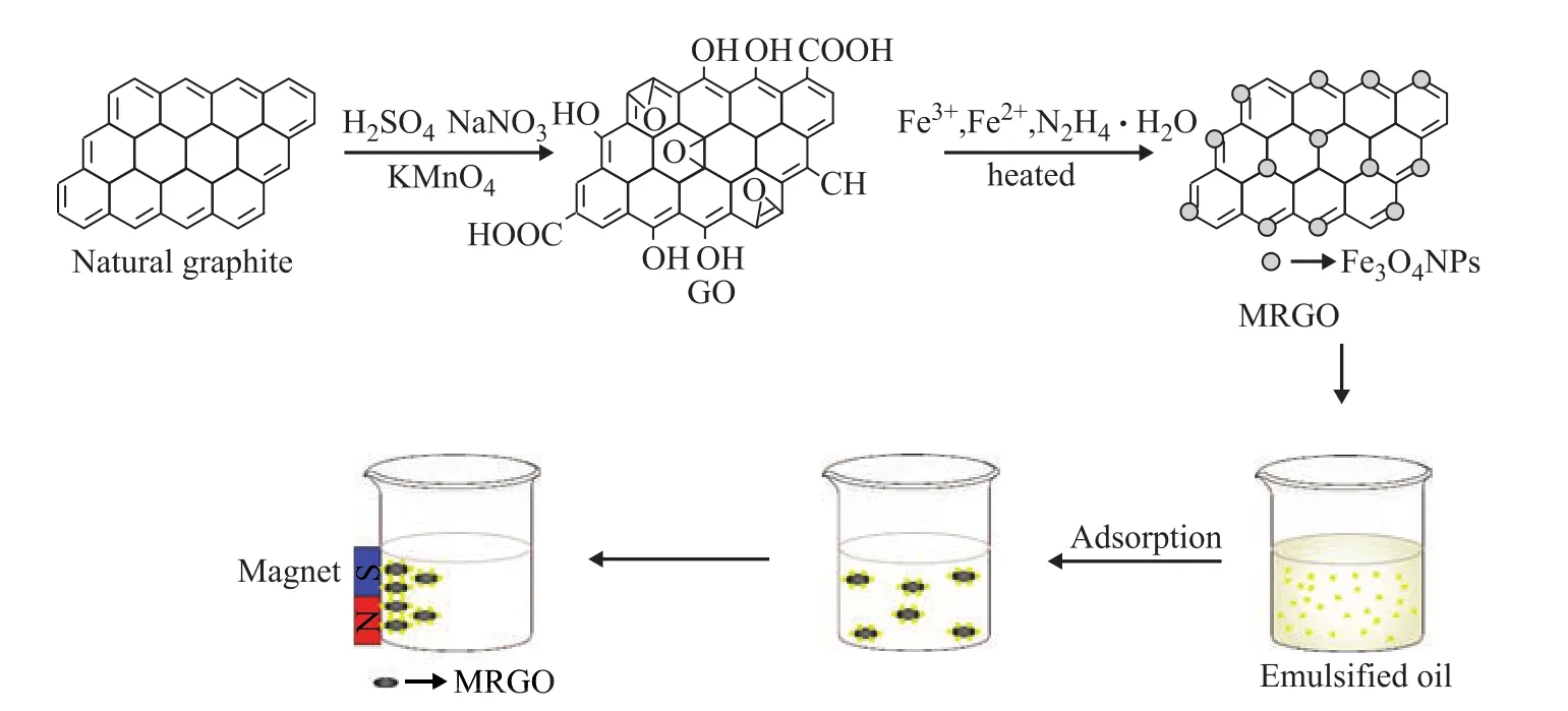
Figure 1 Schematic diagram for the preparation and application of MRGO
2.4 Adsorption experiments
The O/W emulsion was prepared by blending diesel with deionized water. The mixture was emulsified by using an ultrahigh speed homogenizer (Fluko, FA25) at a rotational velocity of 28 000 r/min for 5 min to form an oil-in-water emulsion. The adsorption of emulsified oil by MRGO was performed using the batch equilibrium technique. MRGO(weighing 5 mg, 10 mg, 15 mg, 20 mg, 25 mg, and 30 mg, respectively,) was added to 50 mL of emulsified oil wastewater with a known initial concentration. The adsorption was carried out in a thermostatic bath at 298 K with constant agitation (at 180 r/min). After reaching equilibrium, the MRGO samples were subjected to separation with a permanent magnet and the supernatant was collected to measure the residual concentration of oily pollutant. The supernatant (50 mL) was acidized with 2 mL of H2SO4( at a volume ratio of 1:1), and then was extracted twice by 20 mL of petroleum ether using a 125-mL separating funnel. Then, the liquid was moved into a 50-mL volumetric flask, in which the liquid was mixed with petroleum ether to attain a constant volume of 50 mL. Finally, the absorbance was measured at 225 nm with a UV-visible spectrophotometer. The emulsified oil concentration was measured by Eq. (1):

where C0is the oil concentration in volumetric flask,mg/L; V1and V2are the volume of volumetric flask, and the volume of emulsified oil wastewater, L, respectively.The adsorption capacity qe was calculated through Eq. (2).
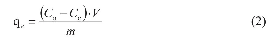
where C0and Ceare the concentration of the initial and the residual emulsified oil in wastewater, mg/L, respectively.V is the volume of the emulsified oil wastewater, L; m is the adsorbent weight, g.
In order to investigate the influence of pH value and temperature on MRGO adsorption capacity, the initial pH value of emulsified oil wastewater was adjusted from 2 to 12. The solution temperature was kept at 10oC to 40oC through each interval of 5 °C. At each initial pH value or temperature, the MRGO sample (20 mg) was mixed with 50 mL of emulsified oil wastewater (150 mg/L) for the determination of qe. Later, the mixture was stirred in a thermostatic bath to reach the equilibrium.
For the adsorption kinetic study, the MRGO sample(20 mg) was added to 50 mL of emulsified oil wastewater(150 mg/L, with a pH value of 7). The mixture was shaken on a thermostatic bath at 298 K in 5—100 min intervals, magnetically separated, and analyzed to measure the emulsified oil concentration in the remaining solution by the above-mentioned methods. The data were analyzed by the pseudo-first-order model, the pseudosecond-order model and the intraparticle diffusion model.For performing the study on isothermal adsorption,the MRGO sample (20 mg) was added to 50 mL of wastewater with different concentration of emulsified oil(covering 50—200 mg/L, with a pH value of 7) under stirring in a thermostatic bath at 298 K for 60 min to reach the equilibrium. The results were fitted to the Langmuir model and the Freundlich model, respectively.
2.5 Desorption experiments
For performing the desorption research, the MRGO sample(20 mg) was added into 50 mL of emulsified oil wastewater
(150 mg/L, with a pH value of 7) and the mixture was shaken on a thermostatic bath at 298 K for 60 min to reach the equilibrium. Then, the MRGO sample was collected by a magnet prior to being added into 20 mL of hexane under stirring for 1 h[13]. After the magnetic separation, the absorbent was dried at 60 °C for 12 h and reused for the next adsorption cycle. The recycling of the adsorbent was performed for six times. The relative adsorption capacity was obtained by qe,n/qe,0, where n was the number of cycles.
3 Results and Discussion
3.1 Characterization of MRGO
The FT-IR spectra of GO and MRGO are shown in Figure 2. The peaks of GO position at 1 060 cm-1, 1 220 cm-1,and 1 620 cm-1correspond to C-O-C stretching vibrations, C-OH stretching, C-C stretching mode of the sp2carbon skeletal network, respectively. The peaks at 1 730 cm-1and 3 400 cm-1correspond to C-O stretching vibrations of COOH groups and O-H stretching vibration,respectively. It can be seen from the FT-IR pattern of MRGO that the peak at 580 cm-1is ascribed to the Fe-O bond vibration, indicating to the existence of fe3O4in the MRGO nanocomposite. Furthermore, it can be seen that C-O, C-O-C and C-OH groups disappear completely,which shows that GO is reduced completely to RGO.
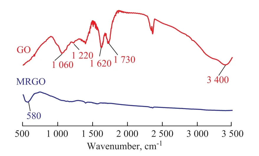
Figure 2 FT-IR spectra of GO and MRGO
Figure 3a shows the XRD patterns of graphite and GO.For graphite, an intense diffraction peak (002) is found at 2θ = 26.35° (d = 0.34 nm), which is in accordance with the standard XRD data (JCPDS No. 41-1487). After graphite is oxidized, the diffraction peak (002) disappears.Simultaneously, a weak diffraction peak at 2θ = 10.6°(d = 0.77 nm) appears, corresponding to the typical diffraction peak of (001) plane of GO. These results suggest that the graphite has been completely oxidized and the layer-to-layer distance is ampli fied which is beneficial to ultrasonic separation[14]. The XRD pattern of MRGO is shown in Figure 3b. Six intense diffraction peaks are observed in the pattern of cubic phase of fe3O4(JCPDS:No. 65-3107) at 2θ=30.2°, 35.5°, 43.1°, 53.5°, 57.2°,and 62.6°, which is indexed as the planes of (220), (311),(400), (422), (511) and (400), respectively[15]. A very weak and broad diffraction peak at 2θ = 24.5° assigned to RGO is found, which indicates that RGO possesses a highly disordered stacked structure[10]. According to Scherrer's equation[16], the average particle size of fe3O4nanoparticles on RGO sheets is calculated to be 28.6 nm.Figure 4a portrays the typical SEM image of GO, which displays a layered structure. The TEM image of GO (Figure 4c) shows that the prepared GO nanosheets are transparent.The transparency reflects that GO is successfully stripped. Figure 4b indicates that Fe3O4nanoparticles(in small size and high density) are evenly distributed on the planes of RGO nanosheets. Owing to the strong interaction of hydrogen bonds between GO and Fe3O4,the Fe3O4nanoparticles can well-distributed on the RGO surface, which can effectively prevent the aggregation of fe3O4nanoparticles[17]. Figure 4d shows the MRGO morphological feature, which is consistent with Figure 4b. It is easy to see that Fe3O4nanoparticles are highly dispersed on the RGO without agglomeration. The average size of fe3O4nanoparticles is about 30 nm, which is in agreement with the calculated value from the Scherrer's relation in the X-ray diffraction pattern (28.6 nm).
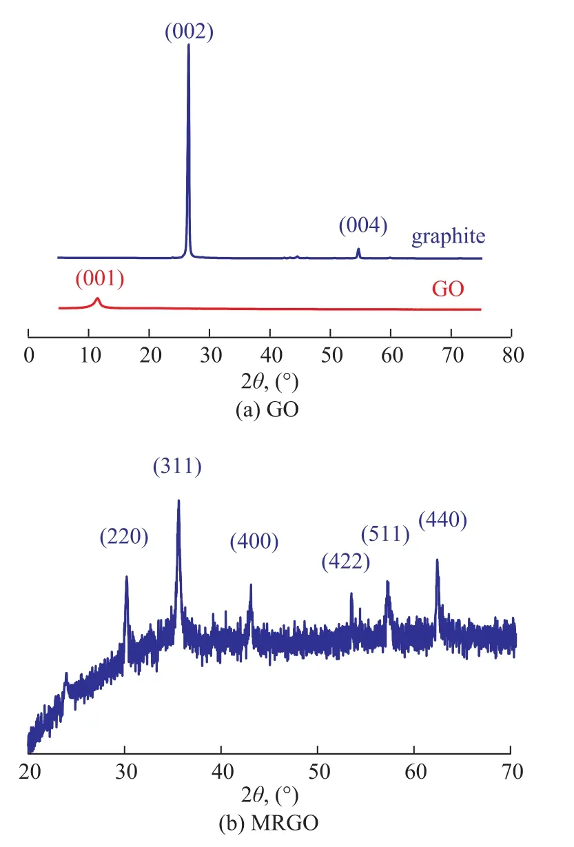
Figure 3 XRD patterns of graphite and GO and MRGO
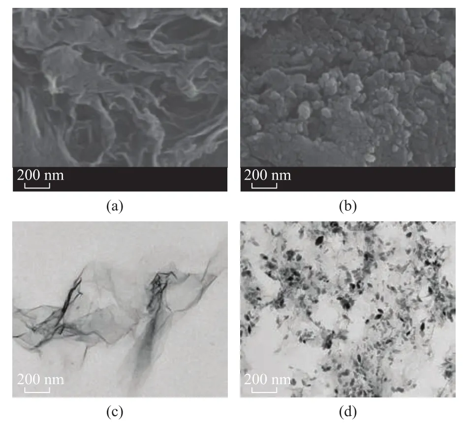
Figure 4 SEM images of GO (a) and MRGO (b), and TEM images of GO (c) and MRGO (d)
In Figure 5, the N2adsorption-desorption isotherm of MRGO exhibits a type IV adsorption pro files with a distinct H2 hysteresis loop at a relative pressure P/P0ranging from 0.4 to 1. This reflects the presence of mesopores. They may be generated from the gaps between Fe3O4and RGO sheets or between RGO sheets[18]. The surface area of MRGO is 306.8 m2/g. The pore volume of MRGO is 0.208 5 cm3/g and its pore size is 3.226 nm, as calculated on the basis of the BJH analysis.

Figure 5 N2 adsorption-desorption isotherm and pore size distribution for MRGO
The magnetic properties of MRGO are determined by VSM. The magnetization hysteresis loop (M-H) of MRGO nanocomposite is shown in Figure 6a. It suggests that MRGO is ferromagnetic. The saturation magnetization(Ms) value is 35.49 emu/g, which is less than that of the reported Fe3O4nanoparticles (92.8 emu/g)[19],and the reduction in the saturation magnetization value might be associated with the relatively low amount of fe3O4loaded on RGO along with the rather small size of fe3O4particles[20]. However, this magnetization degree is strong,which can meet the needs for magnetic separation. According to the magnetic properties of magnetic graphene composites and Fe3O4nanoparticles, it is concluded that the mass ratio of fe3O4nanoparticles in magnetic graphene composites is 38.2%, which is a suitable mass ratio. Figure 6b suggests that MRGO is easily separated from emulsified oil wastewater by a permanent magnet within 2 min. These results indicate that MRGO has good magnetic responsivity and redispersibility,which are important for their practical application.Figure 7 shows that the non-wetting surface that makes a water droplet attain a spherical shape when it is placed on the surface of MRGO with a contact angle (CA) of 150.6°.In contrast, when a diesel oil droplet is dropped on the surface of MRGO, it is immediately absorbed, as indicated by the circle marked area. The result reflects that MRGO is a superhydrophobic-superoleophilic adsorbent.
2018年对于家电行业而言,可以说是举步维艰的一年,整体而言居民购买需求以更新换代需求为主,但是释放缓慢。此外,家电市场外部环境趋劣,受政策空窗,经济放缓,原材料价格持续高位,房地产遇冷等等多重因素影响,家电市场规模增长失速。在这样的情况下,家电市场竞争开始回归市场本源,价值战取代价格战,家电企业调结构,求利润,拼产品、拼技术、拼品牌、拼效率,市场步入精细化竞争时代。
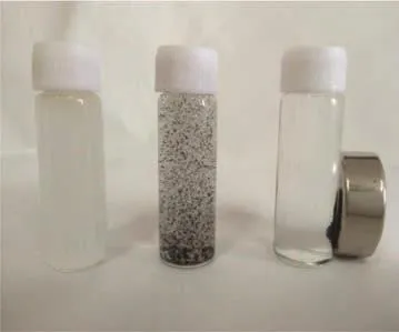
Figure 6 Magnetization curve of the MRGO nanocomposite, and photographs of emulsified oil wastewater (a), MRGO dispersed in the emulsified oil wastewater (b), MRGO and wastewater after applying the magnetic field (c)
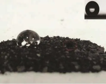
Figure 7 Photograph of drops of water and diesel oil trace on MRGO surface, the inset is an optical image of a water droplet at a CA of 150.6 °
3.2 Effect of MRGO dosage on adsorption capacity and diesel removal efficiency
As shown in Figure 8, MRGO adsorption capacity reduces from 800 mg/g to 209 mg/g with the MRGO dosage increasing from 5 mg to 30 mg. This outcome may be ascribed to the overlap of adsorption sites with excessive MRGO. The diesel removal efficiency reaches 93.5% at a MRGO dosage of 20 mg. Later, the diesel removal efficiency shows slowly on the rise.

Figure 8 Effect of MRGO dosage on adsorption capacity and diesel removal efficiency (with a volume of emulsified diesel solution of 50 mL and an initial concentration of emulsified oil wastewater of 150 mg/ L at an adsorption time of 60 min)
3.3 Effect of temperature on MRGO adsorption capacity and diesel removal efficiency
Figure 9 depicts that the effects of temperature on the MRGO adsorption capacity and the diesel removal efficiency are not significant in the temperature range studied thereby. When the temperature increases from 15 °C to 30 °C, the MRGO adsorption capacity and the diesel removal efficiency slightly increase from 340 mg/g to 350 mg/g and from 90.54% to 93.33%, respectively. However, when the temperature increases to 40 °C, the MRGO adsorption capacity and diesel removal efficiency all slightly decrease.This result may be attributed to the desorption enhancement.
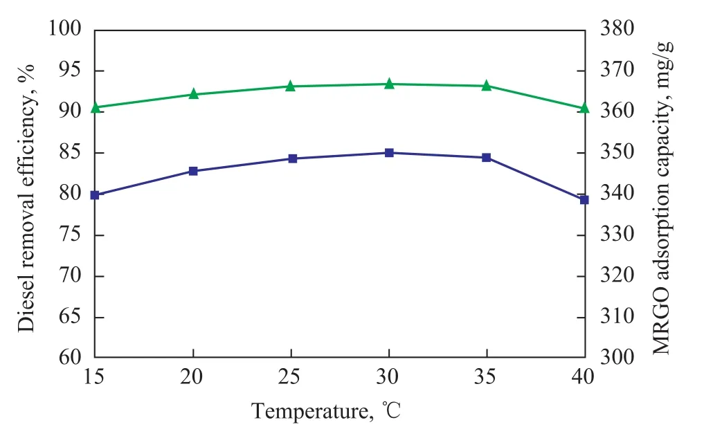
Figure 9 Effect of temperature on MRGO adsorption capacity and diesel removal efficiency (with a MRGO dosage of 20 mg, a volume of emulsified diesel solution of 50 mL,and an initial concentration of emulsified oil wastewater of 150mg/L at an adsorption time of 60 min)
3.4 Effect of solution pH value on MRGO adsorption capacity and diesel removal efficiency
The effects of solution pH value on the MRGO adsorption capacity and the diesel removal efficiency are presented in Figure 10. With the pH value rising from 2 to 12, the MRGO adsorption capacity and the diesel removal efficiency decrease from 358 mg/g to 313 mg/g and from 98.6% to 86.21%,respectively. By comparison, the MRGO adsorption capacity and the diesel removal efficiency in an alkaline environment are lower than those in the acidic condition. In the alkaline environment,the emulsified oil droplets are readily subject to saponification, making the oil droplets in emulsion not easily adsorbed.

Figure 10 Effects of solution pH value on MRGO adsorption capacity and diesel removal efficiency (with a MRGO dosage of 20 mg, a volume of emulsified diesel solution of 50 mL, and an initial concentration of emulsified oil wastewater of 150 mg/ L at an adsorption time of 60 min)
3.5 Adsorption kinetics
According to Figure 11, the adsorption capacity increases with a raising contact time and about 65%of emulsified oil are removed by MRGO in the first 15 min. The equilibrium is attained in 60 min. The data verify that the adsorption process is divided into two stages: viz.: a very rapid surface adsorption and a slow intracellular diffusion[21]. It is clear that the MRGO adsorption capacity and the diesel removal efficiency reach the equilibrium within an adsorption time of 60 min.
In this research, the adsorption kinetics is carried out at 25 °C and a neutral pH value. Figure 12 a,b and c shows the adsorption of emulsified oil on MRGO by using the pseudo-first-order kinetic models[22], the pseudo-second-order kinetic model[23]and the intraparticle diffusion model[24], respectively.The relevant parameters are listed in Table 1. Three models are formulated by Eqs. (3), (4) and (5),respectively.

Figure 11 Effects of adsorption time on MRGO adsorption capacity and diesel removal efficiency (with a MRGO dosage of 20 mg, a volume of emulsified diesel solution of 50 mL, and an initial concentration of emulsified oil wastewater of 150 mg/ L)
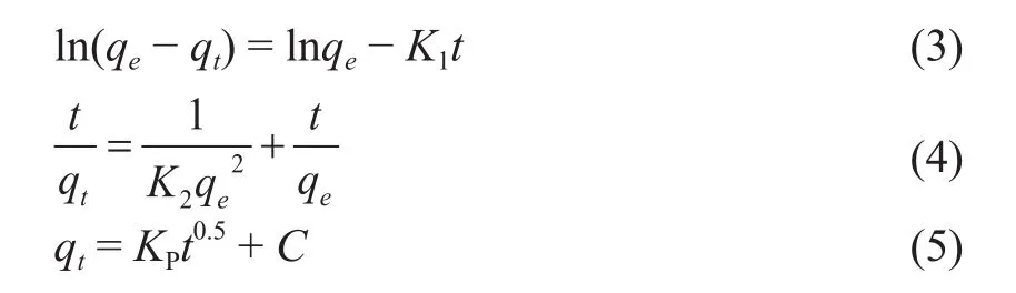
where qtand qeare the adsorption capacity of diesel fuel at time t and at equilibrium, mg/g, respectively; K1is the rate constant of the pseudo- first-order kinetic model,1/min; K2is the rate constant of the pseudo-secondorder kinetic model, g/(mg·min); Kpis the rate constant of intraparticle diffusion model, g/(mg·min1/2); C is a constant.
It can be seen from Table 1 that according to the R2value, the adsorption of emulsified oil onto MRGO is well described using a pseudo-second-order kinetic model. By fitting, the chemical adsorption is the rate controlling step that dominants the adsorption process of emulsified oil onto MRGO. The intraparticle diffusion model is used to explain the adsorption mechanism of the emulsified oil onto MRGO. Figure 12c shows that there is no linear relationship between adsorption data and time. This shows that two stages do occur. The first one is the boundary layer diffusion with high adsorption rate, and the other stage is the intraparticle diffusion[25].
3.6 Adsorption isotherms

Figure 12 Adsorption data fitting: pseudo- first-order kinetic model (a), pseudo-second-order kinetic model (b)and intraparticle diffusion model (c)

Figure 13 Effects of initial concentration of emulsified oil wastewater on MRGO adsorption capacity and diesel removal efficiency (with a MRGO dosage of 20 mg, and a volume of emulsified diesel solution of 50 mL at an adsorption time of 60 min)
The isotherm data are fitted to the Langmuir model[26]and the Freundlich model[27]. They are formulated by Eqs. (6)and (7), respectively. Table 2 lists the fitting parameters.
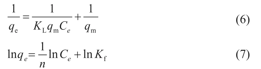
where qeis the adsorption amount at equilibrium, mg/g;qmis the theoretical maximum adsorption capacity, mg/g;KLis the adsorption constant of the Langmuir model,L/mg; Ceis the equilibrium concentration, mg/L; n and Kfare the Freundlich constants related to the adsorptionintensity and adsorption capacity, respectively.

Table 1 Kinetic parameters for the adsorption of emulsified oil onto MRGO

Table 2 Parameters for the Langmuir and the Freundlich adsorption isotherms of emulisi fied oil onto MRGO
It can be seen from Table 2 that the correlation coefficient of the Freundlich model (0.990 7) is higher than that of the Langmuir model (0.980 5). The monolayer adsorption capacity calculated from the Langmuir isotherm is 934 mg/g, which is quite different from the experimental capacity. This reflects that the Freundlich model is more accurate than the Langmuir model for depicting the adsorption process of the emulisi fied oil on MRGO. In the Freundlich model, Kfreflects the adsorption capacity of MRGO and the slope n shows the adsorption intensity of MRGO. When n is greater than 1, it shows the adsorption process becomes easy with the occurrence of chemical reaction. If n is smaller than 1, it shows the adsorption process becomes difficult[28]. As shown in Table 2, the n value is 1.353 (greater than 1), indicating that MRGO adsorption for emulsified oil becomes easy and chemical reaction may take place. This is in accordance with the result of the pseudo-second-order kinetic model.
3.7 Recycling tests
Unlike the traditional throw-away chemical adsorbents,the super-paramagnetic feature of MRGO makes it very attractive in recycling and reusing after adsorption of emulsified oil. The recycling tests are performed at a pH value of 7. Figure 14 depicts the relative adsorption capacity of MRGO in 6 recycling tests. The MRGO adsorption capacity decreases to 70.3% after six recycles.The capacity loss might be resulted from enhancing the adhesion of oil onto the adsorbent by means of chemical adsorption after each recycle and low percentage of oily pollutants desorbed from the hydrophobic surface of MRGO. It is worth mentioning that the MRGO adsorption capacity is still more than 236.1 mg/g after its sixth recycle.
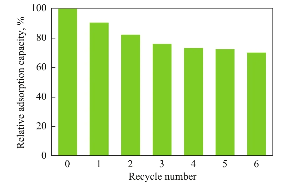
Figure 14 Regeneration stability of MRGO (operating with a MRGO dosage of 20 mg, and a volume of emulsified dieselsolution of 50 mL at an adsorption time of 60 min)
3.8 Adsorption mechanism
Judging from the characterization results of MRGO,we know that MRGO has a large surface area and a high surface hydrophobicity. These characteristics capacitate MRGO to possess high affinity and capacity for adsorption of emulsified oil. In addition, since the diesel fuel consists of low-molecular-weight PAHs which have C=C double bonds and contain π electrons,MRGO may adsorb the emulsified oil by virtue of the ππ electron donor acceptor interactions. These π electrons in diesel can easily interact with π electrons in benzene rings on MRGO via the π-π electron coupling[29]. The main forces of magnetic graphene for adsorption of emulsified diesel cover the hydrophobic interaction, the π-π electron donor acceptor interactions, and the van der Waals force. The π-π electron donor acceptor interactions between magnetic graphene and PAHs which have C = C double bonds and contain π electrons are dominant and constitute the main force of adsorption. According to the Freundlich model, the fitting parameter n is 1.353, which shows that the chemical composition of the adsorption process is dominant. The above research can elucidate the adsorption process which combines the physical adsorption process and the chemical adsorption process.
4 Conclusions
The magnetic reduced graphene oxide (MRGO)nanocomposite was successfully prepared by the chemical coprecipitation approach for the adsorption of emulsified oil from oily wastewater. SEM, TEM, XRD, FT-IR, VSM and other analytical methods were utilized to characterize the prepared MRGO. Owing to the high specific area of RGO and the magnetic properties of fe3O4nanoparticles,the composites showed excellent performance for adsorption of the emulsified oil. At an initial oil concentration of 150 mg/L, the equilibrium adsorption capacity of MRGO was 335.85 mg/g. The MRGO adsorption rate was rapid and reached the equilibrium within 60 min, while the adsorption kinetics could well fit the pseudo-second-order model. The Freundlich model could perfectly depict the adsorption isotherms.The adsorption mechanism covered the hydrophobic interactions, the π-π electron coupling, and the van der Waals force. The adsorption process combined the physical adsorption process and the chemical adsorption process.
Acknowledgments: This study was funded by the Major National Science and Technology Projects of China (Grant No. 2016ZX05040-003) and the Top Talents Project of China University of Petroleum (grant No.2015011).
[1] Ibrahim S, Ang H M, Wang S B. Removal of emulsified food and mineral oils from wastewater using surfactant modified barley straw [J]. Bioresource Technolnology,2009, 100(23): 5744-5749
[2] Liu J, Wang H J, Li X C,et al. Recyclable magnetic graphene oxide for rapid and efficient demulsification of crude oil-in-water emulsion [J]. Fuel, 2017, 189(1): 79-87
[3] Ye C, Hu N, Wang Z. Experimental investigation of Luffa cylindrica as a natural sorbent material for the removal of a cationic surfactant [J]. Journal of the Taiwan Institute of Chemical Engineers, 2013, 44 (1): 74-80
[4] Moazed H, Viraraghavan T. Use of organo-clay/anthracite mixture in the separation of oil from oily waters [J].Energy Source, 2007, 27(1/2): 101-112
[5] Chan L S, Cheung W H, Mckay G. Adsorption of acid dyes by bamboo derived activated carbon [J]. Desalination,2008, 218(1): 304-312
[6] Qiu S, Jiang B, Zheng X, et al. Hydrophobic and fireresistant carbon monolith from melamine sponge: A recyclable sorbent for oil-water separation [J]. Carbon,2015, 84(1): 551-559
[7] Hu H, Zhao Z B, Gogotsi Y, et al. Compressible carbon nanotube-graphene hybrid aerogels with superhydrophobicity and superoleophilicity for oil sorption[J]. Environmental Science Technology Letters, 2014, 1(3):214-220
[8] Qiu S, Yin H C, Zheng J T , et al. A biomimetic 3D ordered multimodal porous carbon with hydrophobicity for oilwater separation [J]. Materials Letters, 2014, 133(41):40-43
[9] Katsnelson M I. Graphene: carbon in two dimensions [J].Materials Today, 2007, 10(1-2): 20-27
[10] Wang H, Yuan X Z, Wu Y,et al. Graphene-based materials:fabrication, characterization and application for the decontamination of wastewater and wastegas and hydrogen storage/generation[J]. Advances in Colloid & Interface Science, 2013, 195-196(7): 19-40
[11] Setshedi K Z, Bhaumik M, Onyango M S, et al. Highperformance towards Cr (VI) removal using multi-active sites of polypyrrole-graphene oxide nanocomposites:Batch and column studies [J]. Chemical Engineering Journal, 2015, 262: 921-931
[12] Hummers W S, offeman R E, Hummers W S, et al.Preparation of Graphitic Oxide [J]. Journal of the American Chemical Society, 1958, 80(6): 1339-1339
[13] Hakimabadi S G, Ahmadpour A, Mosavian M T, et al.Functionalized magnetite / silica nanocomposite for oily wastewater treatment [J]. Advances in Environmental Research 2015, 4(2): 69-81
[14] Lerf A, Buchsteiner A, Pieper J, et al. Hydration behavior and dynamics of water molecules in graphite oxide [J].Journal of Physics and Chemistry of Solids, 2006,67 (5/6):1106-1110
[15] Shen X, Wu J, Bai S, et al. One-pot solvothermal syntheses and magnetic properties of graphene-based magnetic nanocomposites [J]. Journal of Alloys and Compounds,2010, 506(1): 136-140
[16] Bhuvaneswari S, Pratheeksha P M, Anandan S, et al.Efficient reduced graphene oxide grafted porous Fe3O4composite as a high performance anode material for Li-ion batteries [J]. Physical Chemistry Chemical Physics, 2014,16(11): 5284-5294
[17] Gang W, Liu T, Xie X, et al. Structure and electrochemical performance of fe3O4/graphene nanocomposite as anode material for lithium-ion batteries [J]. Materials Chemistry and Physics , 2011, 128 (3): 336-340
[18] Ma Y X, Li Y F, Zhao G H, et al. Preparation and characterization of graphite nanosheets decorated with Fe3O4nanoparticles used in the immobilization of glucoamylase [J]. Carbon, 2012, 50(8): 2976-2986
[19] Zhang Z, Duan H, Li S, et al. Assembly of magnetic nanospheres into one-dimensional nanostructured carbon hybrid materials [J]. Langmuir, 2010, 26(9): 6676-6680
[20] Liu Z, Wang H, Liu C, et al. Magnetic cellulose-chitosan hydrogels prepared from ionic liquids as reusable adsorbent for removal of heavy metal ions [J]. Chemical Communications, 2012, 48(59): 7350-7352
[21] Xuan Z, Tang Y, Li X, et al. Study on equilibrium, kinetics and isotherm of biosorption of lead ions onto pretreated chemically modified orange peel [J]. Biochemical Engineering Journal, 2006, 31(2): 160-164
[22] Wu F, Tseng R L. Kinetic modeling of liquid-phase adsorption of reactive dyes and metal ions on chitosan [J].Water Research, 2001, 35(3): 613-618
[23] Ho Y S, Mckay G. Sorption of dye from aqueous solution by peat [J]. Chemical Engineering Journal , 1998, 70(2):115-124
[24] Mckay G, Blair H S, Gardner J. The adsorption of dyes in chitin. III. Intraparticle diffusion processes [J]. Journal of Applied Polymer Science, 2010, 28(5): 1767-1778
[25] Vimonses V, Lei S, Jin B, et al. Kinetic study and equilibrium isotherm analysis of Congo red adsorption by clay materials [J]. Chemical Engineering Journal, 2009,148(2/3): 354-364
[26] Langmuir I. The adsorption of gases on plane surfaces of glass, mica and platimum [J]. Journal of the American Chemical Society, 1918, 40(12): 1361-1403
[27] Freundlich H M F. Over the adsorption in solution [J] .Journal of Physical Chemistry C, 1906, 57: 385-470
[28] Poots V J P, Mckay G, Healy J J. Removal of Basic Dye from Effluent Using Wood as an Adsorbent [J]. Journal of the Water Pollution Control Federation, 1978, 50(5): 926-939
[29] Guo Y, Deng L, Li J, et al. Hemin-graphene hybrid nanosheets with intrinsic peroxidase-like activity for label-free colorimetric detection of single-nucleotide polymorphism [J]. ACS Nano 2011, 5(2): 1282-1290
“The Fluidized Bed Process for Manufacturing Paraxylene from Methanol/Toluene with Coproduction of Olefins” Developed by Dalian Institute of Chemical Physics Passed Appraisal
The fluidized-bed process for manufacture of paraxylene from methanol and toluene with coproduction of olefins (DMTA), on which the CAS Dalian Institute of Chemical Physics (DICP) has the independent intellectual property rights, has passed the assessment of Scientific achievement organized by China Petroleum and Chemical Industry Federation (CPCIF). The Scientific Achievement Assessment Committee has recognized that this achievement is innovative in nature with independent intellectual property rights and generally commands an internationally leading position. The experts attending the assessment meeting have raised a suggestion to speed up the course of commercialization of the said process and construct a commercial demonstration unit as soon as possible.A designated fluidized catalyst with outstanding performance has been used in the said process, with preparation of the catalyst carried out in the commercial scaleup tests. The process has been tested in an 100 t/a unit for verifying and optimizing the process technology for manufacturing paraxylene from methanol and toluene with coproduction of olefins, and the basic data necessary for compiling the process design package have been collected. The calibration test conducted in 72 hours had revealed that the toluene conversion reached 24.4%, the methanol conversion was 83.0%, and the selectivity of“ethylene+propylene+butylenes+paraxylene” was equal to 79.2% (by weight), while the selectivity of paraxylene among xylenes was 93.2% (by weight).
date: 2017-04-05; Accepted date: 2017-05-08.
Professor Liu Fang, Telephone: +86-532-86980608; E-mail: liufang@upc.edu.cn.
猜你喜欢
杂志排行

中国炼油与石油化工的其它文章
- Thermal Decomposition Behavior of Terephthalate in Inert Gas
- Molecular Simulation of Competitive Adsorption on Fe(110) Between Gasoline Detergent and Deposit: I. Physical Adsorption
- Characterization and Apparent Kinetics of Polymerization of 1-Decene Catalyzed by Boron Trifluoride/Alcohol System
- Preparation of Cu-, Zn-, Co-Zeolites and Application for Adsorptive Desulfurization of Saudi Arabian Medium Crude
- Study on Con fined Impinging Jet Mixer and Mechanism offlash Nanoprecipitation
- Antimicrobial Degradation Performance of Novel Polyacrylamide Derivatives by Microbial Consortia for Enhanced Oil Recovery