骨-骨水泥界面环形凹槽对人工假体生物力学影响的实验研究
2017-09-26沈国琪张春林
沈国琪 张春林
骨-骨水泥界面环形凹槽对人工假体生物力学影响的实验研究
沈国琪 张春林
目的分析新型骨-骨水泥-假体模型在增加环形凹槽后的生物力学和界面微观变化。方法使用刀具对骨床进行处理,使之产生两个环形凹槽,建立新型骨-骨水泥-假体模型,将没有环形凹槽的模型作为对照组。将两种模型使用 Micro-CT 进行检测,计算模型的微观参数。然后将模型使用生物力学测试仪进行生物力学测试。对比分析实验组和对照组的骨-骨水泥界面接触面积和模型孔隙率,生物力学的测试结果,并对模型微观参数和生物力学测试结果进行相关性分析。结果实验组的骨-骨水泥界面的接触面积 ( 5470±265 ) mm2明显大于对照组 ( 5289±299 ) mm2,但是两组之间的孔隙率差异无统计学意义 ( 1.50± 0.382 ) % vs. ( 1.59±0.496 ) %。生物力学测试结果显示:模型的失效主要发生在骨-骨水泥界面。相对于对照组,实验组的抗拉伸 ( 7337±1825 ) N vs. ( 5564±1359 ) N 和抗旋转能力 ( 65.70±4.83 ) N · m vs. ( 60.60± 4.43 ) N · m 明显大于对照组。其次,研究发现模型的抗拉伸和抗旋转能力与骨-骨水泥的接触面积有明显正相关性 R2=0.85 和 R2=0.77,但是与模型的孔隙率成负相关 R2=0.57 和 R2=0.43。有限元分析发现,实验组模型有更小的应力分布现象。结论通过处理使骨质髓腔内壁产生环形凹槽,导致骨水泥和骨质可以更好地进行交锁,增强骨-骨水泥界面的强度,提高骨水泥型人工关节初始稳定性。
界面;骨水泥;人工假体;生物力学
骨水泥即聚甲基丙烯酸甲酯常用于人工关节置换的固定。当前,许多研究集中在改变骨水泥-假体界面固定,但是对于骨水泥型人工关节置换,其远期失效的主要原因是骨-骨水泥界面的无菌性松动[1]。其固定的强度依赖于骨水泥与骨质之间良好的交锁。有研究发现:渗透深度和骨水泥-骨质界面的强度存在正相关性[2]。骨水泥对骨质的渗透深度取决于几个因素,包括骨水泥黏度[3]、骨准备技术[4]、骨水泥的加压输注[5]及骨的质量和形态,这些有助于加强骨水泥-骨界面的机械性能。其次,骨髓腔内壁较多的孔隙将产生剪切强度更高的骨-骨水泥界面[6]。骨-骨水泥界面的强度与两者之间的交锁程度和接触面积有很强的正相关性[7-8]。
在现有的常规手术方案基础上,增加骨-骨水泥界面的交锁程度和接触面积有可能增加界面的机械强度,使骨水泥型人工关节达到更好的初期稳定性,从而增加人工关节的寿命。所以,本实验采用刀具 ( 专利号:CN103315797A ) 对新鲜猪股骨的髓腔内壁进行干预,使股骨髓腔内表面产生两个深度和高度适合的环形凹槽。理论上,进行人工假体组配时,股骨髓腔内表面的环形凹槽可以在骨与骨水泥之间产生更好的界面浸润和接触。与传统的骨-骨水泥界面相比,新界面将有更好的初始稳定性。通过对骨-骨水泥-假体模型的生物力学对比和微观检测以及相关性分析来验证干预的效果。
材料与方法
一、新型骨-骨水泥-假体模型的建立
新鲜猪股骨样本若干。去除周围组织和股骨两端,仅保留股骨干部分。保留股骨干的长度为( 60±1 ) mm。使用医学扩髓器模拟人工关节置换术对股骨干进行逐级扩髓,去除骨髓腔内的骨髓和大部分的松质骨。切割后的股骨放在 -20 ℃ 冰箱内进行保存。将股骨样本按直径大小进行编号,使用Excel 软件进行随机分组,分为拉伸实验组、旋转实验组和拉伸对照组、旋转对照组,每组 10 个样本。使用新型扩髓刀具对实验组的骨髓腔内壁进行二次处理,使实验组股骨的内壁生成两个高 2 mm,深2 mm 的骨皮质凹槽,分别在 20 mm 和 40 mm 处。对照组的髓腔内壁不作该处理。
使用钴铬钼材料模拟人工关节假体,人工假体柄为圆柱状,直径 12 mm,长 50 mm,远端有光滑的弧面,外表镀有粗糙的微孔结构。在假体柄外有一固定杆,规格 14 mm×14 mm×30 mm,固定杆中间有一直径为 8 mm 的圆柱状孔洞,使其可以在后续生物力学测试仪器上进行固定和测试。人工骨水泥在真空条件下进行搅拌,然后在骨水泥处于面团期时逆行导入股骨髓腔内。插入钴铬钼材料的模拟型人工假体,并在人工假体的固定杆施加 200 N 的恒压 120 s,直到人工骨水泥充分凝固( 图1 )。股骨髓腔直径和人工假体决定了骨水泥的厚度为 3 mm 左右,这样被认为骨水泥假体有最低的失效率[9]。
二、Micro-CT 检测
将所有的模型都使用 Micro-CT ( 通用电气公司 )进行扫描。样本通过假体柄外的固定杆被垂直倒立放置在测试仪的固定钳上。每次扫描顺时针旋转0.19°,电压 240 KV,电流 200 μA,分辨率 45 μm,平均扫描时间 ( 90±5 ) min。扫描后使用 DATOSX 软件进行图像采集,然后进行重建可视化。再将图像转换到 VGstudio 软件中,对图像进行基于骨、骨水泥、人工假体的 CT 灰度强度的单独阈值所进行的三维重建 ( 图2 )。使用 VGstudio 软件计算出每个模型的总体积、骨水泥体积、骨体积、孔隙体积、骨-骨水泥的接触面积、骨水泥壳的平均厚度。孔隙率是模型的孔隙体积与总体积的比值。由于人工假体是钴铬钼材料,在图像重建时,金属假体对骨水泥和骨质的图像影响很大。试验中将人工金属假体图像从模型中提取出来,然后再对模型进进行分析和计算,避免金属假体对骨-水泥界面的影响。
三、生物力学测试
采用拉扭复合生物力学试验机进行生物力学测试。在生物力学测试过程中,模型被垂直固定在生物力学试验机上 ( 图3 )。在进行测试之前,需要对样本采取适应载荷来消除骨质松弛和蠕变的影响,使模型产生适应,频率 2 Hz,载荷 -100~100 N,时间 15 s。在拉伸测试过程中,施加垂直向上的初始载荷 100 N,位移比 2 mm / min,每秒产生 20 个数据。旋转组是施加垂直于模型纵轴的扭转载荷,初始载荷 100 N,旋转率 5° / min,每秒产生 20 个数据。实时观察测试进程,当标本出现骨皮质骨折、骨-骨水泥界面或骨水泥-假体界面出现明显分离、人工假体断裂时,即认为模型失效,停止测试,此时的最大载荷,即模型失效载荷。根据加载数据绘出每个样本的加载曲线即载荷-位移曲线。每个样本的拉伸或者旋转实验都是在相同的条件下进行。
四、有限元分析
基于 Mirco-CT 扫描的图像对模型进行有限元建模,使用 ANSYS14.0 分别创建实验组和对照组的网格。模型的初始材料特性被认为是线性弹性和等向性的。股骨、骨水泥和假体的杨氏模量[10]分别设置为 16.7、3.0、200 G pa,泊松比为 0.3。基于 Mirco-CT 灰度值的骨质使用校准模型转换为等值 HA-密度。HA-密度和杨氏模量间的假设线性关系使骨质的杨氏模量为 0.1~20 000 M pa ( n=0.3 )。在拉伸试验中,假设在生物力学时,在模型假体的顶端施加一个大小为 2.4 KN 的垂直载荷。在扭转试验中,施加一个 40 N · m 的旋转扭矩。
五、统计学处理
数据的描述采用 Shapiro-Wilk-test 进行检验。两样本 t 检验使用 Bonferroni 校正多重比较,使用双向 t 检验,P<0.05 为差异有统计学意义。将骨-骨水泥-假体模型的 Micro-CT 的微观检测实验结果与生物力学的实验数据进行回归分析预测,了解相互之间的相关性。所有的统计分析均使用 SPSS 18.0 ( SPSS,Chicago,Illinois ) 进行统计学分析。
结 果
一、Micro-CT 测试结果
对模型进行 Micro-CT 检测后,将实验组和对照组的参数进行对比。实验组 ( 5470±265 ) mm2相对于对照组 ( 5289±299 ) mm2有更大的接触面积 ( P<0.05 )。孔隙率两组间差异无统计学意义 ( P>0.05 ),( 1.50±0.382 ) % vs. ( 1.59±0.496 ) % ( 表1 )。
表1 对照组和实验组的 Micro-CT 检测结果对比 (±s )Tab.1 Control group and experimental group of Micro-CT test results (±s )
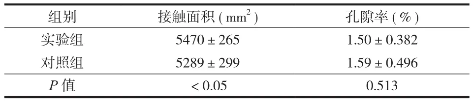
表1 对照组和实验组的 Micro-CT 检测结果对比 (±s )Tab.1 Control group and experimental group of Micro-CT test results (±s )
组别 接触面积 ( mm2) 孔隙率 ( % )实验组 5470±265 1.50±0.382对照组 5289±299 1.59±0.496 P 值 <0.05 0.513
二、生物力学测试结果
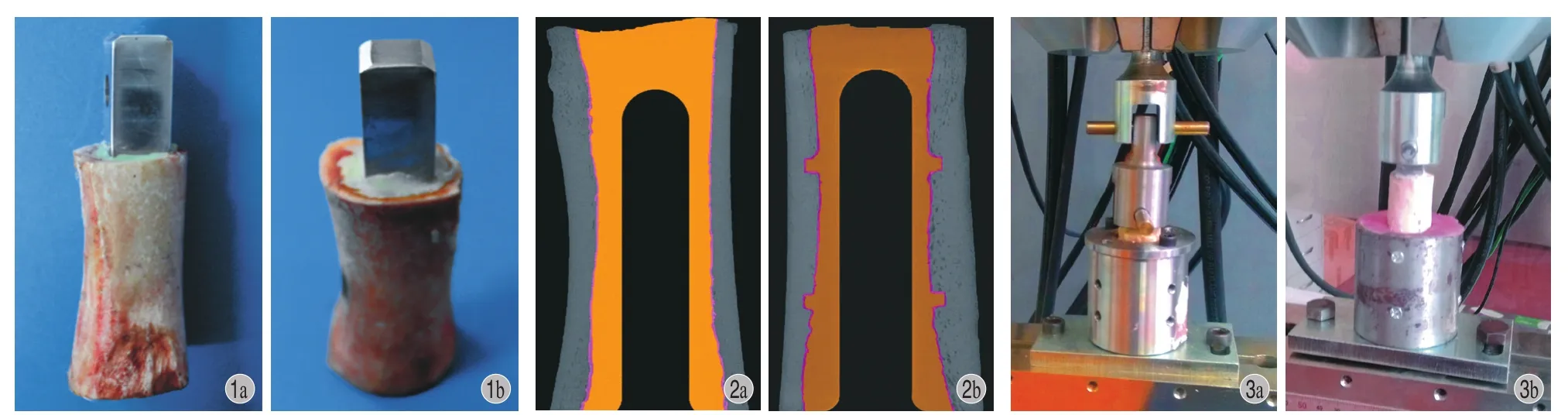
图1 骨 - 骨水泥 - 假体模型的建立图2 对照组 ( a ) 和实验组 ( b ) 的 Micro-CT 检测图。实验组通过新型刀具处理,在新鲜股骨髓腔内壁的 20 mm 和 40 mm 处分别有一个高约 2 mm 、深约 2 mm 的环形凹槽。其中,中间黑色为人工钴络钼假体,黄色为骨水泥,灰色为股骨图3 生物力学测试图;左边为拉伸实验生物力学测试,右边为旋转实验生物力学测试Fig.1 The model of bone-cement-prosthesis componentFig.2 The Micro-CT detection of bone-cement-prosthesis component, control group ( a ) and experimental group ( b ). In the experimental group, 20 mm and 40 mm in the inner wall of the fresh femoral medullary cavity were treated with a new type of cutting tool to have a circular groove with height of about 2 mm and depth of about 2 mmFig.3 Biomechanical test; the left side of the biomechanical test was tensile test, and the right side was the rotating biomechanical test
在拉伸试验中,样品全部在骨-骨水泥界面失效,即在骨水泥-骨界面产生了明显位移。实验组( 7337±1825 ) N 相对于对照组 ( 5564±1359 ) N 有更好的抗拉伸能力 ( P<0.05 )。在旋转实验中,17 个样品在骨-骨水泥界面产生失效,但是对照组有一个是由于纵形骨折产生的失效,而实验组为 2 个( 图4 )。实验组 ( 65.70±4.83 ) N · m 相对于对照组( 60.60±4.43 ) N · m 有更好的抗旋转能力 ( 表2 )。
表2 对照组和实验组的生物力学测试对比 (±s )Tab.2 Comparison of biomechanical tests between the control and experimental group (±s )

表2 对照组和实验组的生物力学测试对比 (±s )Tab.2 Comparison of biomechanical tests between the control and experimental group (±s )
组别 接触面积 ( mm2) 孔隙率 ( % )实验组 7337±1825 65.70±4.83对照组 5564±1359 60.60±4.43 P 值 <0.05 <0.05

图4 生物力学测试前后具有代表性的样本 a:拉伸实验前的模型;b:拉伸试验后的模型,可见骨 - 骨水泥界面出现了明显相对位移;c:旋转实验前的模型;d:旋转试验后的模型,可见股骨皮质出现了纵形骨折;e:旋转试验后的模型,在骨 - 骨水泥界面出现了明显位移 ( 黑色标注 )Fig.4 Tesponses after the biomechanical test: before tensile test ( a ); after tensile test-the stretched displacement occurred at the bone-cement interface of all the samples and the cement-prosthesis interface did not have a displacement ( b ); before torsion test ( c ), after torsion test -longitudinal fracture of the femoral cortex ( d ), -cortical bone fractures occurred in the samples, and significant loosening of the bone-cement interface was observed, while loosening of the cement-prosthesis interface was not observed ( e )
三、生物力学和微观检测的相关性分析
对 Micro-CT 的检测结果和生物力学的测试结果进行线性回归分析后发现:在拉伸实验中,包括实验组和对照组,接触面积和骨-骨水泥-假体模型的最大载荷之间有较高的相关性 ( R2=0.85 );同样,在旋转实验中,包括实验组和对照组,接触面积和骨-骨水泥-假体模型的最大扭矩也有较大的相关性 ( R2=0.77 )。其次,骨-骨水泥-假体模型的孔隙率和模型的最大载荷和最大扭矩之间也是有关系的,R2=0.57 和 R2=0.43 ( 图5 )。
在有限元分析中,实验组模型的拉伸和旋转峰值应力 23.48 M pa 和 161.5 M pa 均明显低于对照组27.62 M pa 和 182.3 M pa ( 图6 )。同样,在拉伸和旋转分析中,实验组的股骨组件的应力峰值明显低于对照组。在实验组的股骨凹槽中发现了应力集中,拉伸和旋转应力大小分别为 7.9 M pa 和 30 M pa,可是股骨的屈服载荷约 150 M pa,所以在实验组的环形凹槽内没有发生失效 ( 图7 )。
讨 论
在骨水泥型人工关节置换手术后,骨与骨水泥界面的完整性对于术后的人工关节稳定和使用寿命是非常重要的[11-12]。翻修手术取出的骨水泥壳上大量的裂纹证明:早期骨水泥损害主要发生在骨-骨水泥界面,界面的缺陷可以促进人工假体系统的失效[13]。假体组件的初始固定强度是植入物的长期使用寿命的主要影响因素[14]。另外,骨水泥渗透对植入物也有非常重要的作用,可以创建一个理想的骨与骨水泥交锁界面,从而有更好的界面初始固定强度[15]。有学者证明,在全膝关节置换手术后,胫骨组件的骨与骨水泥之间较大的初始交锁会产生更稳定的结构,更少的微动和更长的植入物寿命[16]。反向研究也发现:大多数植入物的失效是由劣质的骨水泥灌注技术所引起,较差的骨水泥浸润是一个重要的不利因素[17]。通过充分的骨床准备和骨水泥加压所产生的骨水泥和骨间的交锁,被认为是关节假体置换中产生良好初始固定的重要因素[18]。最新的骨水泥技术的主要目的在于让骨与骨水泥达到更好的交锁所产生的人工假体固定,以达到更好的临床治疗效果,包括:使用脉冲灌洗股骨髓腔、放置远端骨水泥塞、逆行加压灌注骨水泥和使用生物型骨水泥,即将羟基磷灰石颗粒加入骨水泥中,来增加骨-骨水泥界面的结合力[19-22]。还有学者使用振动力学原理设计了一个骨水泥振荡器,来增加骨-骨水泥界面的交锁能力,理论上的结果也是可行的[23]。
本实验使用刀具对骨质内壁进行髓腔扩髓后的处理,使骨质内壁形成两个深 2 mm,高 2 mm 的环形骨质凹槽。在凹槽处理后,使用脉冲灌洗来清理所产生的骨微粒,防止骨微粒对骨-骨水泥界面产生影响。理论上,在进行骨水泥的灌注时,骨水泥会进入内壁凹槽,并形成两个凸向股骨内壁的圆形骨水泥环,从而增加骨与骨水泥的接触界面和更好的骨水泥浸润程度,产生更好的植入物初始固定强度。Arola 等[24]通过使用特制工具使骨质内表面产生各种不同的表面纹理,并且证明初始位移和植入物稳定性依赖于骨表面的形态。但是其使用的工具的结果是产生了一个总长 2 mm,深度和宽度只有0.2 mm 并行排列的多凹槽纹理。在骨水泥的加压灌注过程中,由于骨水泥的黏性,导致骨水泥并不一定能很好地进入骨髓腔内壁新的凹槽内,缺少骨髓腔内壁骨水泥浸润的有效证据。
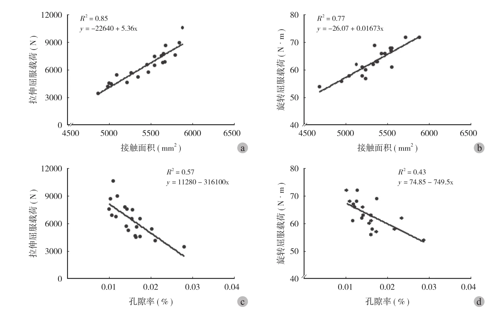
图5 线性相关模型 a:拉伸负荷和接触面积的线性相关 R2= 0.85;b:旋转扭矩和接触面积的线性相关 R2= 0.77;c:拉伸负荷和孔隙率的线性相关 R2= 0.57;d:旋转扭矩和孔隙率的线性相关 R2= 0.43Fig.5 Linear regression models a: Tensile stress and contact area, R2= 0.85; b: Tensile stress and porosity, R2= 0.57; c: Maximum torque and contact area, R2= 0.77; d: Maximum torque and porosity, R2= 0.43; P < 0.05

图6 骨 - 骨水泥 - 假体模型的应力分布图。在拉伸和旋转分析中,实验组的峰值应力均小于对照组Fig.6 Under the tension and rotation loads, the von Mises stress in the components of the experimental group was lower than that in the components of the control group
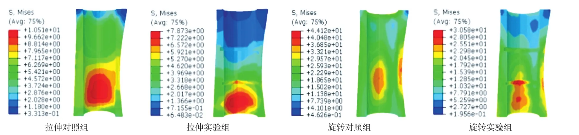
图7 骨干的有限元分析应力分布。在拉伸和旋转测试中可以发现:实验组相对于对照组有更低的应力分布Fig.7 Under the tension and rotation loads, the von Mises stress in the femur of the experimental group was lower than that in the femur of the control group
研究结果表明:使用了特殊刀具处理后的骨质内壁表面上,骨水泥可以很好地浸润到内壁表面上的环形凹槽内,并在骨-骨水泥界面形成了一个特殊的骨与骨水泥交锁,骨水泥-假体界面并没有通过增加骨-骨水泥界面间的骨小梁和骨水泥的交锁,能改善界面强度,增强假体柄的固定效果,减少假体柄松动[25]。本研究结果显示新型扩髓组相对于传统扩髓组有着更多的骨与骨水泥接触面积。接触面积对于骨-骨水泥界面的强度有显著正相关性[26-27]。
此结论与既往的研究结论类似:骨-骨水泥-假体模型的失效应力和骨-骨水泥界面的接触面积有着较高的相关性,无论是在拉伸张力组 ( R2=0.85,P<0.0001 ),还是旋转剪切组 ( R2=0.77,P<0.0001 )。结合前面的结果可以相信,在本研究中,骨与骨水泥界面的接触面积与界面的强度也有较高正相关性,所以增加骨水泥对骨质的接触有助于增加界面的强度。增加骨-骨水泥界面的交锁强度同时也能减少微动的发生,从而减少骨水泥磨屑的产生。而且,当骨水泥-骨界面形成一个稳定封闭的界面后,引起炎性反应、骨溶解和骨松动的磨损颗粒不能进入骨-骨水泥界面,防止异物炎性反应及溶骨反应,减少了松动的发生。
其次,本研究结果还显示孔隙率与固定强度之间存在一定的负相关性。这也说明真空混合骨水泥和加压灌注有助于减少模型内的孔隙,降低孔隙率,从而增加骨-骨水泥界面的强度[28-29]。但是Oliver 等对臼杯内的骨水泥进行研究后发现:机械因素是导致植入物失效的最主要因素,骨水泥的孔隙率对植入物的长期作用是非常有限的,甚至可以忽略[30]。也有学者证明:真空混合骨水泥并没有减少骨水泥壳的整体孔隙率和增加骨-骨水泥界面的强度,只是影响了孔隙率的分布[31],所以对于孔隙率和固定强度的关系是有争议的。
在有限元分析中,实验组的模型拉伸和旋转整体应力分布都明显小于对照组。说明新增凹槽使模型应力减小。同样,在股骨干的应力图上,发现了同样的现象。虽然实验组股骨干的环形凹槽上的应力有集中现象,但是明显小于股骨的屈服载荷,所以并不会对股骨干产生破坏,也就不会增加假体周围骨折的风险。也就说明,新增骨髓腔内壁的环形凹槽所导致的骨水泥壳应力降低并不会增加人工的松动风险。
本研究的不足是研究局限于实验室样本,界面失效的过程只是在机械方面的结果。对于磨屑微粒和网状纤维组织在人体内产生的生物化学反应并没有进行研究。将解剖与实验室制备的样本进行比较后发现:尸体的骨-骨水泥界面有更低的界面参数,可能是由于体内的一系列生物化学反应[32-33]。
本实验使用一种新型的工具来改变骨髓腔内壁的表面形态。骨质内壁的变化使人工骨水泥能够更好地和骨进行相互交锁,从而增加骨-骨水泥界面的初级稳定性和生物力学强度,最终延长人工假体的使用寿命。
[1] Juliusson R, Flivik G, Nilsson J, et al. Circulating blood diminishes cement penetration into cancellous bone: In vivo studies of 21 arthrotic femoral heads[J]. Acta Orthop, 1995, 66(3):234-238.
[2] Miller M A, Race A, Gupta S, et al. The role of cement viscosity on cement-bone apposition and strength: an in vitro model with medullary bleeding[J]. J Arthroplasty, 2007, 22(1):109-116.
[3] Race A, Miller MA, Clarke MT, et al. The effect of lowviscosity cement on mantle morphology and femoral stem micromotion: a cadaver model with simulated blood flow[J]. Acta Orthop, 2006, 77(4):607-616.
[4] Berry DJ. Cemented femoral stems: What matters most[J]. J Arthroplasty, 2004, 19(4):83-84.
[5] Gozzard C, Gheduzzi S, Miles AW, et al. An in-vitro investigation into the cement pressurization achieved during insertion of four different femoral stems[J]. Proc Inst Mech Eng H, 2005, 219(6):407-413.
[6] Amirfeyz R, Bannister G. The effect of bone porosity on the shear strength of the bone–cement interface[J]. Int Orthop, 2009, 33(3):843-846.
[7] Mann KA, Miller MA, Cleary RJ, et al. Experimental micromechanics of the cement–bone interface[J]. J Orthop Res, 2008, 26(6):872-879.
[8] Waanders D, Janssen D, Mann KA, et al. The mechanical effects of different levels of cement penetration at the cementbone interface[J]. J Biomech, 2010, 43(6):1167-1175.
[9] Fisher DA, Tsang AC, Paydar N, et al. Cement-mantle thickness affects cement strains in total hip replacement[J]. J Biomech, 1997, 30(11):1173-1177.
[10] Lotz JC, Gerhart TN, Hayes WC. Mechanical properties of metaphyseal bone in the proximal femur[J]. J Biomech, 1991,24(5):317-329.
[11] Jasty M, Maloney WJ, Bragdon CR, et al. Histomorphological studies of the long-term skeletal responses to well fixed cemented femoral components[J]. J Bone Joint Surg Am, 1990, 72(8):1220-1229.
[12] Tong J, Wong KY, Lupton C. Determination of interfacial fracture toughness of bone-cement interface using sandwich Brazilian disks[J]. Eng Fract Mech, 2007, 74(12):1904-1916.
[13] Race A, Miller MA, Ayers DC, et al. Early cement damage around a femoral stem is concentrated at the cement / bone interface[J]. J Biomech, 2003, 36(4):489-496.
[14] Hofmann AA, Goldberg TD, Tanner AM, et al. Surface cementation of stemmed tibial components in primary total knee arthroplasty: minimum 5-year follow-up[J]. J Arthroplasty, 2006, 21(3):353-357.
[15] Janssen D, Mann KA, Verdonschot N. Micro-mechanical modeling of the cement-bone interface: the effect of friction, morphology and material properties on the micromechanical response[J]. J Biomech, 2008, 41(15):3158-3163.
[16] Miller MA, Terbush MJ, Goodheart JR, et al. Increased initial cement-bone interlock correlates with reduced total knee arthroplasty micro-motion following in vivo service[J]. J Biomech, 2014, 47(10):2460-2466.
[17] Krause M, Breer S, Hahn M, et al. Cementation and interface analysis of early failure cases after hip-resurfacing arthroplasty[J]. Int Orthop, 2012, 36(7):1333-1340.
[18] Ritter MA, Herbst SA, Keating EM, et al. Radiolucency at the bone-cement interface in total knee replacement. The effects of bone-surface preparation and cement technique[J]. J Bone Joint Surg Am, 1994, 76(1):60-65.
[19] Ni GX, Choy YS, Lu WW, et al. Nano-mechanics of bone and bioactive bone cement interfaces in a load-bearing model[J]. Biomaterials, 2006, 27(9):1963-1970.
[20] Reading AD, McCaskie AW, Barnes MR, et al. A comparison of 2 modern femoral cementing techniques: analysis by cementbone interface pressure measurements, computerized image analysis, and static mechanical testing[J]. J Arthroplasty, 2000, 15(4):479-487.
[21] Schlegel UJ, Püschel K, Morlock MM, et al. An in vitro comparison of tibial tray cementation using gun pressurization or pulsed lavage[J]. Int Orthop, 2014, 38 (5):967-971.
[22] Herberts P, Malchau H. Long-term registration has improved the quality of hip replacement: a review of the Swedish THR Register comparing 160,000 cases[J]. Acta Orthop, 2000, 71(2):111-121.
[23] Wang Y, Han P, Gu W, et al. Cement oscillation increases interlock strength at the cement--bone interface[J]. Orthopedics, 2009, 32(5):325.
[24] Arola D, Stoffel KA, Yang DT. Fatigue of the cement / bone interface: the surface texture of bone and loosening[J]. J Biomed Mater Res B Appl Biomater, 2006, 76(2):287-297.
[25] Miller MA, Eberhardt AW, Cleary RJ, et al. Micromechanics of postmortem-retrieved cement-bone interfaces[J]. J Orthop Res, 2010, 28(2):170-177.
[26] Waanders D, Janssen D, Mann KA, et al. The mechanical effects of different levels of cement penetration at the cementbone interface[J]. J Biomech, 2010, 43(6):1167-1175.
[27] Mann KA, Miller MA, Cleary RJ, et al. Experimental micromechanics of the cement-bone interface[J]. J Orthop Res, 2008, 26(6):872-879.
[28] Baleani M, Bialoblocka-Juszczyk E, Engels GE, et al. The effect of vacuum mixing and pre-heating the femoral component on the mechanical properties of the cement mantle[J]. J Bone Joint Surg Br, 2010, 92(3):454-460.
[29] Evans SL. Effects of porosity on the fatigue performance of polymethyl methacrylate bone cement: an analytical investigation[J]. Proc Inst Mech Eng H, 2006, 220(1):1-10.
[30] Coultrup OJ, Hunt C, Wroblewski BM, et al. Computational assessment of the effect of polyethylene wear rate, mantle thickness, and porosity on the mechanical failure of the acetabular cement mantle[J]. J Orthop Res, 2010, 28(5):565-570.
[31] Messick KJ, Miller MA, Damron LA, et al.Vacuum-mixing cement does not decrease overall porosity in cemented femoral stems: an in vitro laboratory investigation. J Bone Joint Surg Br, 2007, 89(8):1115-1121.
[32] Miller MA, Goodheart JR, Izant TH, et al. Loss of cementbone interlock in retrieved tibial components from total knee arthroplasties[J]. Clin Orthop Relat Res, 2014, 472(1):304-313.
[33] Goodheart JR, Miller MA, Mann KA. In vivo loss of cement-bone interlock reduces fixation strength in total knee arthroplasties[J]. J Orthop Res, 2014, 32(8):1052-1060.
A biomechanical analysis of the annular groove on the bone - cement interface
SHEN Guo-qi, ZHANG Chun-lin. Department of Orthopedics, the tenth People’s Hospital of Shanghai, Shanghai, 200072, China
ObjectiveTo identify whether the strength of bone-cement interface could be increased by changing the morphology of inner wall of bone medullary canal with grooves.MethodsSelf-developed new reamer was used to process fresh pig reamed femoral canal, resulting in two cortical grooves in the canal wall of the experimental group. We used the Micro-CT to scan all the models, and observed the infiltration of cement and to determin the differencs between the new bone-cement interface and the traditional interface. We used the biomechanical testing instrument to test the new and traditional bone-cement-prosthesis model ( tensile testing and rotation testing ), until the model failed. The biomechanical strength of both models was compared. We analyzed the correlation between the results of microscopic detection and biomechanical testing.ResultsThe contact area of the bone-cement interface was greater for the experimental group ( 5470 ± 265 ) mm2when compared to the specimens of the control group ( 5289 ± 299 ) mm2. However, the porosity for the experimental group ( 1.50 ± 0.382 ) % was similar to that of the control group ( 1.59 ± 0.496 ) %. In addition, biomechanical responses to tensile loading ( 7337 ± 1825 ) N vs. ( 5564 ± 1359 ) N and anti-rotation capability ( 65.70 ± 4.83 ) N · m vs. ( 60.60 ± 4.43 ) N · m showed that the specimens of the experimental group had stronger strains at the bone-cement interface compared to the control group. In the tensile testing, the contact area of bone-cement interface and the tensile force of models had strongly significant positive correlation ( R2= 0.85 ). In the rotational testing, the contact area of bone-cement interface and the maximal torsion had a strong correlation ( R2= 0.77 ). The relationships between the tensile force and the porosity and themaximal torsion and the porosity were observed. ( R2= 0.57 and R2= 0.43 ). The FEA results compared favorably to the tensile and torsion relationships determined experimentally.ConclusionsConverting the standard reaming process from a smooth boring cortical tube to one with grooves permits the cement to interlock with the reamed bony wall. This would increase the strength of the bone-cement interface. We believe that the addition of such grooves has the potential to enhance cement fixation to the bone, provide better initial fixation and extend longevity of the bone-cement-implant composite.
Interface; Bone cements; Artificial prosthesis; Biomechanical
ZHANG Chun-lin, Email: shzhangchunlin@163.com
10.3969/j.issn.2095-252X.2017.09.009
TQ314, Q66
上海浦江人才计划 ( 13PJD023 );上海交通大学医工交叉研究基金 ( YG2012MS49 )
200072 上海市第十人民医院骨科 ( 沈国琪、张春林 )
现在工作单位:215500 江苏,常熟市第二人民医院骨科
张春林,Email: shzhangchunlin@163.com
2016-11-29 )
( 本文编辑:李贵存 )
作者申明:此文章无利益冲突
