Liquid-holdup regions research of novel reactive distillation column for C5 fraction separation
2017-05-28LiangGuoTiefengWangDongfengLiJinfuWang
Liang Guo ,Tiefeng Wang ,Dongfeng Li,Jinfu Wang ,*
1 Beijing Key Laboratory of Green Reaction Engineering and Technology,Department of Chemical Engineering,Tsinghua University.Beijing 100084,China
2 Beijing Research Institute of Chemical Industry,Beijing 100013,China
1.Introduction
The cracking C5 fraction is the by productin the steam cracking of the naphtha and other heavy hydrocarbon in ethylene plants,in which isoprene(IP),cyclopent adiene(CPD)and pentadiene are the main components and account for 40 wt%–60 wt%in total[1–6].These dienes,especially IP,are important synthetic materials due to their high chemical activities.For the synthesis utilization,the purity requirement for IP is generally rigorous(IP≥99.8%and CPD≤3×10⁻⁶),so a good separation of IP and CPD is crucial[7–9].
As the boiling point of IP(34.1 °C)is close to that of CPD(41.5 °C),it is hard to separate them by conventional distillation.Instead,the thermal dimerization method has been widely employed in industry for better separation of the C5 fraction.In the thermal dimerization process,C5 fraction is heated for 1–3 h(<130 °C)to convert CPD to dicyclopentadiene(DCPD)in the dimerization reactor.In the subsequent operation,DCPD and IP can be easily separated by conventional distillation because of the higher boiling point of DCPD(166.6°C)[10,11].However,besides the self-dimerization of CPD in the dimerization reactor,the selfdimerization of IP and dimerization of CPD with IP(or 1,3-butadiene(1,3-BD))also occur,thus producing(IP+IP)dimerand(CPD+IP)dimer(or(CPD+BD)dimer)byproduct,respectively[12].Although the conversion ratio of CPD can exceed 80%,the recovery of IP is only 88%–92%which is much lower than the requirement of 98%[13].
On the other hand,reactive distillation,a hybrid process where chemical reaction and distillative separation are performed simultaneously,was wildly researched for esterification[14–16],etherification[17,18],transesterification[19,20],alkylation[21]and dimerization[22]process.In the 1990s,Huet al.found that reactive distillation processes were very effective to separate CPD from the cracking C5[4].In the reactive distillation column,IP accumulates at the top whereas CPD flows towards the bottom due to their different boiling points.Meanwhile,CPD has a much higher dimerization activity and therefore is largely converted to DCPD on the feed plate.As a consequent result,the concentration of CPD decreases rapidly both upwards and downwards.The lower concentration of CPD along the column reduces the copolymerization of CPD with IP and thus improves the recovery of IP.In this sense,it is important to study the reactive distillation of C5 fraction for process intensification.In spite of some simulation studies on the C5 reactive distillation(RD)reported in the literatures[23–25],experimental researches are still limited.Even in the reported simulation studies,the effects of process parameters,such as the number of theoretical plates,feed position,re flux ratio and residence time,were not considered.
As is wildly perceived,the coordination of distillation temperature and reaction temperature is extremely important in reactive distillation process.In C5 RD,however,limited by the distillation temperature,the self-dimerization of CPD is not efficient enough,while the side reactions,especially dimerization of CPD with IP,cannot be neglect.Hence in this work,a novel reactive distillation column with liquid-holdup regions was designed for the separation of cracking C5 fraction and a corresponding mathematic model was established in Aspen Plus.Using the model,the number of theoretical plates,feed position and liquid-holdup regions position were optimized in detail,and the influences of some important factors were also investigated.
2.Experimental
2.1.Reagents
The cracking C5 fraction used in this experiment is a by-product of the ethylene unit cracking with naphtha in a certain petrochemical corporation.Its composition is listed in Table 1.The mass fractions of IP,CPD and DCPD are 18.03%,16.97%and 2.17%,respectively.
2.2.Apparatus
As shown in Fig.1,the liquid phase flowing down from the packing bed 1 came into contact with the gas phase rising from the riser 2,and then flowed down from the over flow vent 5 to the packing bed below.The gas rising from the bottom of the lower packing bed flowed into the liquid phase in the liquid-holdup region to prevent the formation of dead zones.The RD column was 50 mm in diameter and packed with Φ4 mm×4 mm stainless steel cannon rings.There were five packing sections connected with flanges in the column,the length of which were respectively 1,1.5,0.5,1 and 1.5 m from top to bottom.Six thermocouple points were installed on the column,denoted as T1–T6.For ease of analysis,seven sampling ports were installed at the feed tank,at each hold-up region from top to bottom and at the re flux tank,respectively.The feed preheater,the reboiler and the thermal preservation of the column were all electrically heated while the cooler and the condenser were cooled with the cooling water.
A schematic diagram of the experimental apparatus is shown in Fig.2.The apparatus can be divided into four parts.The first part is the feedstock part containing the feed tank 1,the feed pump 2,and the feed preheater 3.The cracking C5 fraction is pumped from tank 1 to the RD column after being heated to 60°C by preheater 3.The second part is the reactive distillation 4 where the mass transfer and chemical reactions of C5 occurred.The third part consists of the condenser 5,the re flux tank 6,the re flux pump 7 and the overhead product tank 8.The re flux rate is controlled by a dosing pump.The last one is the bottom discharge part including the product cooler 9 and the product tank 10 at the column bottom.
3.Reaction Kinetics
In spite of the complex composition of the cracking C5 fraction,only three types of detected reactions,namely the self-dimerization,the codimerization and the multi-polymerization exist in the polymerization process of C5 fraction.Under the operating temperature,the dimerization of CPD producing DCPD is the main reaction,while other reactions including the self-dimerization of IP,co-dimerization of CPD with IP and 1,3-BD are significant side reactions[23].Though the multi-polymerization,which produces polymers,may cause serious implications,experiment studies and industrial productions show that it is negligible.Therefore only these two types of reactions were considered in this work.
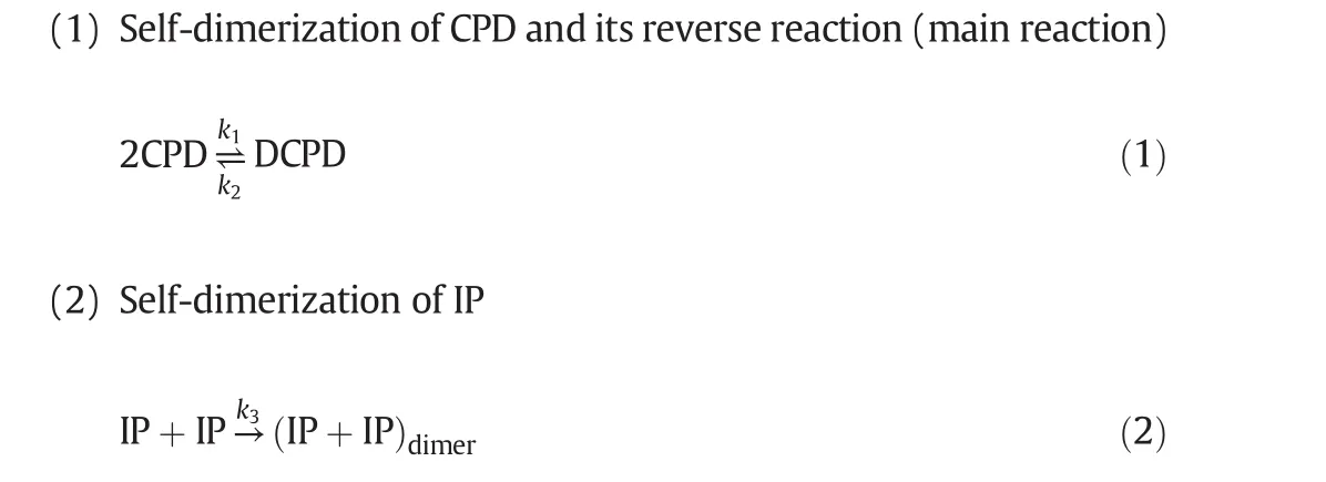

Fig.1.The schematic diagram of the connection of holdup region and packing bed in RD.1—upper packing bed;2—gas riser;3—holdup region;4—thermocouple point;5—over flow weir;6—sample point;7—lower packing bed.

Table 1Composition of steam creaking C5


Fig.2.Schematic diagram of the experimental apparatus.1—Feed tank;2—feed pump;3—pre-heater of material;4—RD;5—cooler;6—re flux accumulation;7—re flux pump;8—product tank at column top;9—product cooler at column bottom;10—product tank at column bottom;T1–T7:thermocouple points.
The reverse reactions of(2)–(4)are weak and neglected in this work.
The reaction rate constantkof above Reactions(1)–(4)can be expressed as follows:

Some works have been carried out to study the kinetics of Reactions(1)–(4),but the temperature involved ranging from 80 to 130°C was not in accordance with RD operation condition[25,26].According to our previous work[27],the kinetics parameters of the reactions are listed in Table 2.
4.Mathematic Model
The reactive distillation is complex because the reaction and distillation take place simultaneously.To simplify the problemin this work,the balances of mass,phase and heat in the RD column were all studied in terms of the RADFRAC model in Aspen Plus with some reasonable assumptions:(1)only the dimerization reactions were considered;(2)the gas–liquid phase equilibrium was reached atevery plate without considering the disturbance of dimerizaitons;(3)all dimerizations were dominated by the reaction kinetics;(4)heat loss was negligible.
The RD diagram was shown in Fig.3,in which the column plates were numbered as 1,2,…,Nfrom the top to the bottom.The first stage represented the condenser and theNth stage was the reboiler.There was a feed inlet at every stage.Under the above assumptions,the balance equations for thejth stage are listed as follows:


Table 2Parameter values of the reaction kinetic model

Fig.3.The diagram of reactive distillation column of separation cracking C5 fraction.

activity coefficient of liquid(γ)and fugacity coefficient of vapor(φ)are calculated in UNIFAC equation[28].

wheni=m,Eqs.(17)–(19)represent the kinetic model of the selfdimerization of componenti.
5.Results and Discussion
5.1.Experiment of reactive distillation
5.1.1.Number of theoretical plates
The number of theoretical plates is one of the major evaluating parameters affecting the separation efficiency in a distillation column.In this work,N-hexane and methyl cyclopentane were selected to determine the number of theoretical plates because of their easy separation.The mixture ofN-hexane and methyl cyclopentane was rectified in the RD column(Fig.2)with total re flux at the atmospheric pressure.After the temperature pro file was no longer changing,samples at both the top and the bottom were taken and analyzed(Table 3).

Table 3Composition of top product and bottom product
Then the number of theoretical plates can be calculated by Fensake's correlation,i.e.

where the subscripts 1 and 2 respectively denote the light and heavy components,the subscripts D and W respectively represent the top and bottom products and α12is the relative volatility between components 1 and 2(α12=1.0897 under the atmospheric pressure).The total number of theoretical plates was determined to be 38.5 and hence the number in each bed was obtained(see Table 4).

Table 4Number of theoretical plates in each packing bed
5.1.2.Measurement of liquid holdup
The liquid holdup is anothercritical parameter for the reactive distillation because it determines the residence time.In this work,the liquid holdup was defined as the total volume of the liquid at the pack surfaces as well as that in the pack pores,the holdup regions and the column bottom.
The liquid volume from each holdup region was 224 ml;therefore the sum for the four holdup regions is 896 ml.When the RD column was operated under the normal conditions given in Table 5,the feed and the re flux were shut down and the products drawing from the top and the bottom was stopped,and the liquid level was recorded.At this time,the liquid level in the bottom was 60%with the corresponding holdup of 2182 ml.After the column was cooled down,the volume of liquid at the bottom was 4657 ml with 2475 ml increases.Consequently,the liquid holdup of the RD column was 3371 ml.

Table 5Operating conditions in experiments
5.1.3.Validation of mathematic model
To verify the accuracy of the mathematic model,the reactive distillation process was investigated by both experimental and simulated tests under the same conditions listed in Table 5.Slightly different from the experiments,the calculated number of the oretical plates was 42,in which the first plate and the last one represented the condenser and the reboiler respectively.In addition,the liquid-holdup regions were not included in theoretical plates in the simulation.The liquid volume was 64 ml at one plate,224 ml in every holdup regions and 2182 ml in the column bottom.
As shown in Fig.4,the temperature pro file in the column obtained by the simulation was close to that in experiments.The slight difference was probably caused by the heat loss of the column,which was not considered in the simulations.In addition,the temperature along the column ranged between 50 and 90°C which was covered by the applicability region of the reaction kinetics parameters to ensure the model accuracy.According to the calculated reaction rate constant,co-dimerization of CPD with IP is the main side reaction in this temperature range.
Comparing the concentration distribution of IP,CPD and DCPD shown in Fig.5,good agreement between the simulation and experiment was achieved.Moreover,the simulation results shown in Table 6 also matched well with the experiment results with a relative error less than 2%.On the other hand,it was found that a longer residence time was favorable to increase the conversion of CPD.As a consequence result,the separation efficiency of IP was also benefited.However,the recovery of IP was much lower than 98%and the concentration of IP in the bottom reached up to 4.65%.Such results suggested that 42 theoretical plates were inadequate and detailed optimization of process parameters was needed to ensure the recovery of IP larger than 98%.
5.2.Simulation of reactive distillation
In general,for the separation of C5 fraction,there are three main indexes should meet the requirement,namely,the recovery of IP is larger than 98%,the conversion of CPD is larger than 90%and the selectivity to DCPD is larger than 98%.Due to the constraints and limitations in the experimental study,some of the important RD design parameters could not be studied experimentally.The validated mathematic model was hence used for further research.
5.2.1.Preliminary determination of number of theoretical plates and feed position
For the original RD column,theoretical plates are far from adequacy.It should be note that,in this RD column,reactions mostly occur in the liquid-holdup regions,so the number of theoretical plates mainly affects the distillation efficiency.Therefore,the number of theoretical plates was firstly investigated without considering the liquid-holdup regions.As shown in Fig.6(A),the recovery of IP increased rapidly with the increases of number of theoretical plates ranging from 50 to 100,but improved slightly when the number of theoretical plates was more than 100.On the other hand,the conversion of CPD increased with the increases of number of theoretical plates in the range of 50 to 120 due to the increasing of residence time,but the maximum CPD conversion with 120 theoretical plates was only 78.6%,which indicated that simply adding the number of theoretical plates can hardly make the RD column meet the design requirement.As a practical remark,100 theoretical plates were recommended to ensure the RD results.

Fig.4.Temperature pro file in the RD column.(A)Feed flow:0.76 kg·h−1,Re flux rate:15 L·h−1.(B)Feed flow:0.93 kg·h−1,Re flux rate:18 L·h−1.

Fig.5.Liquid concentration pro files in the RD column.(A)Feed flow:0.76 kg·h−1,Re flux rate:15 L·h−1.(B)Feed flow:0.93 kg·h−1,Re flux rate:18 L·h−1.simulation data;IP experimental data;CPD experimental data;DCPD experimental data.
The feed position determines the number of column plates in both the rectifying and stripping sections and hence has influence on the separation results.As for RD column,proper feed position is especially important,for it can minimize the contact of CPD with IP and hence reduce the side reaction.Shown in Fig.6(B),the recovery of IP increased first and then decreased when the feed position moved downwards from the 10th plate to the 80th plate with the maximum IP recovery obtained between the 30th to 40th plates.Meanwhile,the selectivity to DCPD showed similar variation trend,so the feed stage was selected at the 35th plate.

Table 6Comparison of the experimental and calculated results of the RD
5.2.2.Determine of liquid-holdup regions
The design of liquid-holdup regions is the core of this study.Replacing a theoretical plate with a liquid-holdup region will significantly increase the residence time,hence enhancing the CPD conversion.The side reactions,however,have also been improved somewhat,and consequently reduced the recovery of IP and selectivity to DCPD.Proper location of liquid-holdup regions is critical for the design of the RD column.So,the generation rate of DCPD as well as the ratio of the generation rate of DCPD and(CPD+IP)dimeron each plate were taken into account as research objects(Fig.7).The changes of recovery of IP,conversion of DCP and selectivity to DCPD with the increase of number of liquid-holdup regions are shown in Fig.8.Residence time of all the liquid-holdup regions was preliminarily set as 200 s.
Shown in the curve without liquid-holdup region(Fig.7(A)),the maximum selectivity occurring around 90th plate reached 330 due to the large concentration difference between CPD and IP in this area.Meanwhile,the generation rate of DCPD was also considerable.It is undoubtedly that the first liquid-holdup region installed in this area could benefit the dimerization of CPD but also ensure the selectivity to DCPD.When the 90th plate was set as the first liquid-holdup region,the conversion of CPD enhanced significantly from 72.6%to 81.7%,causing generation rate of DCPD at the common plates between 80 and 100th reduced,while the selectivity around this area was still high(Fig.7(B)).Taking both the rate and selectivity of DCPD generation into consideration,the second liquid-holdup region was set at 75th plate,and the conversion of CPD further increased to 84.3%.In addition,it can be seen that the generation rate of DCPD at the first liquid-holdup region reduced,because the second region is closer to the feed plate to convert more CPD.When considering the third liquid-holdup region,the low generation rate of(CPD+IP)dimershould be given priority,for the conversion of CPD is pretty high.On the other hand,due to the low boiling point,there is a certain amount of CPD in the top product with low residence time.After some evaluation,the third liquid holdup region was set at 25th plate,which is above the feed plate.From the view of the results,the design is reasonable,for the conversion rate of CPD reached 87.6%,while the recovery rate of IP remained unchanged.For further enhancing CPD conversion to 90%,the fourth and the fifth liquid-holdup regions could also be set.As shown in Fig.7(D),the selectivity to DCPD is higher at the plates away from the feed position.In this way,the fourth and fifth liquid-holdup regions were set at 60th and 45th plate respectively to minimize the generation of(CPD+IP)dimer.
As shown in Fig.8,with the number of liquid-holdup regions increasing from zero to four,the recovery of IP reduced slightly from 98.6%to 98.5%,while the conversion of CPD enhanced significantly from 72.6%to 89.2%.The results proved the importance of liquidholdup regions and the rationality of the liquid-holdup regions position design.Further increase of the number of liquid-holdup regions to five didn't improved the CPD conversion obviously,but it improved the self-dimerization of IP and co-dimerization of IP and CPD,hence raising the conversion of IP and reducing both the recovery of IP and selectivity to DCPD.So the optimal number of liquid-holdup regions was four with the position of 25th,60th,75th and 90th plate.

Fig.6.In fluence of(A)number of theoretical plates and(B)feed stage on separation performance.Conditions:Residence time in each plate=5 s,re flux ratio=8,operating pressure=245 kPa.
Fig.9 shows the mass fraction pro files of CPD and IP along the column.As indicated by the mass fraction of IP shown in Fig.9(B),the distillation efficiency is almost not affected by the adding of liquidholdup regions.The results suggested that the determination of the number of theoretical plates and feed position is correct.On the other hand,the adding of liquid-holdup regions mainly affects the CPD content in the plates nearby(Fig.9(A)).
According to the calculation result previously,four liquid-holdup regions are suitable for design requirement.However,the design requirement was not well met,for the conversion of CPD is lower than 90%.Therefore the residence time should also be considered.It should be noted that increases of the residence time may improve the CPD conversion as well as the side reactions according to analysis.As revealed in Fig.10,only conversion of CPD is slightly sensitive to the changes of residence time,while the recovery of IP,selectivity to DCPD and conversion of IP are basically unchanged.The results further proved the rationality of liquid-holdup regions.On the other hand,the large range of residence time from 250 to 400 s merely increased the conversion of CPD from 89.9%to 91.5%,which means the design of residence time for this RD column is simple.

Fig.7.Generation rate and selectivity to DCPD on each plate.Generation rate of DCPD(mol·h-1)Generation selectivity.

Fig.8.Influence of number of liquid-holdup regions on RD performance.
5.2.3.Influence of important operating parameters
For RD process,operation pressure,which determines the temperature distribution,is a key parameter to affect the dimerization reactions.As shown in Fig.11,with the increases of operating pressure,the conversion of both CPD and IP enhanced,but the selectivity to DCPD and recovery of IP decreased.It is worth noting that the separation performance is very sensitive to the operating pressure.When the operating pressure was more than 300 kPa,IP recovery of less than 96%was obtained,which suggested that high operating pressure is very unfavorable for the separation.On the other hand,when the operating pressure is less than 230 kPa,the conversion of CPD cannot reach 90%.So the RD column could be operated in the range of 230 to 260 kPa.
In the distillation processes,the re flux ratio,an important operation parameter,affects both the separation performance and energy consumption.Fig.12 shows the conversion of CPD,the selectivity to DCPD,and the recovery and conversion of IP as a function of the reflux ratio at a fixed residence time.As is well-known,the increasing of reflux ratio enhances the distillation separation efficiency.Hence,the recovery of IP increased with re flux ratio increasing.Moreover,the codimerization of IP with CPD,the major side reaction,was also inhibited due to the less contact of CPD and IP.However,when the re flux ratio increased above 12,IP recovery was improved slightly,but the dimerization of IP can be promoted.In spite the conversion of CPD kept increasing,the selectivity to DCPD slowly declined.Considering these changing trends as well as the high utilities consumption and even the appearance of flooding caused by large re flux ratio,the appropriate re flux ratio could be selected as 8–12 to ensure the separation requirement.

Fig.9.Mass fraction distribution of(A)CPD and(B)IP on each plate.
6.Conclusions
In this work,a new type of reactive distillation column has been designed,in which the pack section and special liquid-holding areas were combined to make the distillation and the reactions work synergistically.The designed multiple liquid-holdup regions supply more residence time and provide flexibility for narrowing the efficiency gap between reaction and distillation.Thus a corresponding mathematic model was established and validated for the detailed research of the RD column.According to the DCPD generation rate and selectivity in each plate, five liquid-holdup regions were set at proper positions in sequences.The well-designed liquid-holdup regions enhance the CPD conversion significantly,while affect slightly on the CPD selectivity and IP recovery.Optimized process parameters were then determined:100 theoretical plates,feed position of 35th plate,and four liquidholdup regions at 25th,60th,75th and 90th plate respectively,with which the technical requirement of C5 separation can be well met.The synergistic effect between reaction and separation overcomes the equilibrium limitations and constrains the undesired side reaction.Overall,the reactive distillation process is a promising technique for the cracking C5 fraction separation.

Fig.10.In fluence of residence time of liquid-holdup regions on RD performance.

Fig.11.In fluence of operating pressure on RD performance.

Fig.12.Conversion of CPD and IP,recovery of IP and selectivity to DCPD at different re flux ratios.
Nomenclature
Apre-exponential factor
Cnumber of components
Ddistillation flow rate of overhead,kmol·s−1
Eactive energy,J·mol−1
Ffeed flow rate,kmol·s−1
hFfeed enthalpy,kJ·mol−1
hLliquid enthalpy,kJ·mol−1
hVvapor enthalpy,kJ·mol−1
kijequilibrium constant
kimreaction rate constant,kmol·s−1
Lliquid flow rate,kmol·s−1
Ntotal number of stages
ppressure,MPa
p0saturated vapor pressure of pure component under the system temperature,MPa
Qheat removed or added,kJ·s−1
Qrheat of reaction,kJ·mol−1
Rgas constant,J·mol−1·K−1
rimdimerization reaction rate constant of componentiandm,kmol·s−1
ritotal reaction rate constant of componenti,kmol·s−1
Ttemperature,K
tresidence time,s
Vvapor flow rate,kmol·s−1
Wbottom product flow rate,kmol·s−1
xmolar fraction of liquid component
ymolar fraction of vapor component
zmolar fraction of feed component
γ activity coefficient of liquid
φ fugacity coefficient of vapor
φ0fugacity coefficient of pure component under saturated vapor pressure
φijfugacity coefficient of mixture component
Subscripts
i,mcomponent,i=1,2,…,C
jtotal number of stages or number of differential unit,j=1,2,…,N
[1]L.Guo,D.Li,J.Wang,Progresses in the separation of steam cracking C5 fraction at home,Petrochem.Technol.44(2)(2015)252–260.
[2]L.Wang,J.Yang,J.Liu,Development and utilization of C5 distillate,Sci.Technol.Chem.Ind.21(5)(2013)83–86.
[3]L.Zhang,Development and application of steam cracking C5 fraction,Petrochem.Ind.Appl.27(4)(2008)16–18.
[4]J.Hu,X.Li,H.Xu,Y.Lu,P.Li,Study of co-dimerization in C5 reaction-distillation,Petrochem.Technol.27(4)(2001)53–58.
[5]R.Baur,A.P.Higler,R.Taylor,R.Krishna,Comparison of equilibrium stage and nonequilibrium stage models for reactive distillation,Chem.Eng.J.76(1)(2000)33–47.
[6]B.Zhang,M.Wang,Z.Luo,S.Wang,Q.Dai,Y.Hu,Z.Cheng,Development of etherification reaction for pyrolysis C5 olefins and application,Petrol.Ref.45(3)(2015)30–35.
[7]X.Chen,Z.Bao,Polymerization of dienes in C5 fraction by ionic liquid catalyst,Petrochem.Technol.36(3)(2007)232–236.
[8]J.Liu,X.Wang,Z.Zhang,J.Li,Formation of dicyclopent adiene by thermal dimerization from C5 fractions,Petrochem.Technol.25(4)(1996)248–252.
[9]S.Zhao,J.Huang,F.University,Fuzhou and Tianjin,Coupled reaction/distillation process for hydrolysis of methyl acetate,Chin.J.Chem.Eng.18(5)(2010)755–760.
[10]S.Sun,G.Huang,Simulation of reactive distillation process for monosilane production via redistribution of trichlorosilane,Chin.J.Chem.Eng.22(3)(2014)287–293.
[11]H.Tian,Z.Huang,T.Qiu,Reactive distillation for producing n-butyl acetate:experiment and simulation,Chin.J.Chem.Eng.20(5)(2012)980–987.
[12]H.-C.Hsu,S.-J.Wang,J.D.-Y.Ou,D.S.H.Wong,Simplification and intensification of a C5 separation process,Ind.Eng.Chem.Res.54(40)(2015)9798–9804.
[13]X.Wang,Z.Bao,Study on thermal dimerization of dienes in C5 fraction,J.Nanj.Univ.Technol.21(5)(2005)737–742.
[14]D.Singh,R.K.Gupta,V.Kumar,Simulation of a plant scale reactive distillation column for esterification of acetic acid,Comput.Chem.Eng.73(2015)70–81.
[15]R.Kumar,S.M.Mahajani,Esterification of Lactic Acid with n-Butanol by Reactive Distillation,Ind.Eng.Chem.Res.46(21)(2007)6873–6882.
[16]M.A.Santaella,A.Orjuela,P.C.Narváez,Comparison of different reactive distillation schemes for ethyl acetate production using sustainability indicators,Chem.Eng.Process.96(2015)1–13.
[17]Z.Qi,K.Sundmacher,E.Stein,A.Kienle,A.Kolah,Reactive separation of isobutene from C4 crack fractions by catalytic distillation processes,Sep.Purif.Technol.26(2002)147–163.
[18]A.M.Katariya,R.S.Kamath,K.M.Moudgalya,S.M.Mahajani,Non-equilibrium stage modeling and non-linear dynamic effects in the synthesis of TAME by reactive distillation,Comput.Chem.Eng.32(10)(2008)2243–2255.
[19]Y.Fang,W.Xiao,Experimental and modeling studies on a homogeneous reactive distillation system for dimethyl carbonate synthesis by transesterification,Sep.Purif.Technol.34(1–3)(2004)255–263.
[20]T.Keller,A.Górak,Modelling of homogeneously catalysed reactive distillation processes in packed columns:Experimental model validation,Comput.Chem.Eng.48(2013)74–88.
[21]B.Guo,Y.Li,Analysis and simulation of reactive distillation for gasoline alkylation desulfurization,Wildl.Soc.Bull.38(1)(2014)43–50.
[22]L.Tong,L.Chen,Y.Ye,Z.Qi,Kinetic studies on the dimerization of is obutene with Ni/Al2O3as a catalyst for reactive distillation process,Chin.J.Chem.Eng.23(3)(2015)520–527.
[23]J.Cheng,X.Li,C.Du,L.Liao,D.Li,Study on C5 separation with reaction distillation,Chem.Ind.Eng.Prog.28(7)(2009)1278–1281.
[24]L.Guo,D.Li,J.Wang,Simulation of reactive distillation process for separation of steam cracking C5,Petrochem.Technol.43(12)(2014)1394–1400.
[25]B.Tian,G.Tang,Q.Zhang,C.Du,W.Dai,Simulations of thermal dimerization and reactive distillation processes in separation of cyclopentadiene from steam cracking C5,Petrochem.Technol.37(12)(2008)1276–1281.
[26]H.J.Flammersheim,J.Opfermann,The dimerization of cyclopentadiene—A test reaction for the kinetic analysis of DSC measurements and the performance of a kinetic evaluation program,Thermochim.Acta337(1–2)(1999)149–153.
[27]L.Guo,T.Wang,D.Li,W.Jinfu,Intrinsic kinetic modeling of thermal dimerization of C5 fraction,Chin.Pet.Process Pe.Technol.18(1)(2016)92–99.
[28]J.Seo,J.Lee,H.Kim,Isothermal vapor–liquid equilibria for ethanol and n-pentane system at the near critical region,Fluid Phase Equilib.172(2)(2000)211–219.
杂志排行
Chinese Journal of Chemical Engineering的其它文章
- Suppressing secondary reactions of coal pyrolysis by reducing pressure and mounting internals in fixed-bed reactor☆
- Transformation mechanism of nutrient elements in the process of biochar preparation for returning biochar to soil☆
- Preparation of cross-linked enzyme aggregates of nitrile hydratase ES-NHT-118 from E.coli by macromolecular cross-linking agent☆
- Development of a new cleaner production process for cassava ethanol☆
- Multi-objective regulation in autohydrolysis process of corn stover by liquid hot water pretreatment
- Modelling of adsorption of textile dyes over multi-walled carbon nanotubes:Equilibrium and kinetic