Effect of surface property on mass flux in a variable-section microchannel☆
2017-05-28WeichengXuYumeiYongJunboXuChaoYang
Weicheng Xu ,Yumei Yong *,Junbo Xu Chao Yang ,**
1 Key Laboratory of Green Process and Engineering,State Key Laboratory of Biochemical Engineering,Institute of Process Engineering,Chinese Academy of Sciences,Beijing 100190,China
2 University of Chinese Academy of Sciences,Beijing 100049,China
1.Introduction
Recently,the Micro-Electro-Mechanical-Systems(MEMS)have been widely used in chemistry,biology and medicine[1].It is found that the size of micro fluidic device is so small that it produces many different flow phenomena from the macro systems.For example,there is an abnormal increase of the mass flux of the liquid in the hydrophobic microchannel over the hydrophilic ones,which cannot be explained by the law of macro fluid dynamics[2].This specific phenomenon can reduce the permeation driving pressure[3],as well as enhance mixing and diffusion-osmotic flows[4],and it has wide applications[5].However,the factors of such phenomenon are still in controversy[2],therefore a systematic study about this phenomenon is desired[6].
A generally accepted explanation on this phenomenon is that the liquids still slip on the liquid–solid interface like gases because of the repulsive force between the wall and fluids,which increases mass flux dramatically in the microchannel[7].Up to now,there have been many studies on this abnormal phenomenon of mass flux in the hydrophobic microchannel[8].Josephet al.[9]used the particle image velocimetry(PIV)technology to investigate the velocity pro files in a thin microchannel and measured the slip length directly.Kopliket al.[10]used the molecular dynamics(MD)technique to study the fluid behavior in the microscopic scale,and found that the boundary slip could be observed in a low density fluid system,and the slip length was related to the flow state.Chenet al.[11]used the lattice Boltzmann method(LBM)to investigate the factors on the boundary slip in a Couette flow,and found that the factors that could induce a low density region near the wall would affect the slip length.Chenget al.[12]measured the mass flux of different liquids in a straight microchannel with different characteristic sizes.The experimental results indicated that when the wall could not be wetted by liquid,the measured mass flux for the microchannel would be bigger than theoretical expectation,and with the increase of system size,the effect of hydrophobic wall on mass flux decreased.It is clear that most of the studies are based on a simple straight microchannel with consistent surface property.However,the practical micro fluidic systems are more complex than straight microchannels and the surface wettability is not always consistent.In order to improve our understanding of the liquid flow in micro scales,more practical situations should be considered.
Among various micro fluidic systems,a microchannel with complex shapes or complex surface wettability can often be found[13,14].Fanet al.[15]applied a MD method to simulate a nano-channel which included a contraction and diverging geometry,and the numerical results had been compared to the prediction results of Navier–Stokes equations.They found that the macro hydromechanics theory was unable to describe the micro flow correctly.Hanasakiet al.[16]simulated water flowing through a carbon nanotube nozzle which had a converging transition section,then they discovered an increase in fluid velocity and a decrease in pressure drop when water flowed through the nozzle.While Guoet al.[17]simulated fluid flowing on a curved surface,and found a dramatic influence of the curvature on the slip length.Some other articles focused on the micro/nano-channel with mixed surface wettability[18,19].However,these works did not mention how the shape and surface wetting property affected jointly on the mass flux.Thus,in this paper we are going to study the relationship between hydrophobic surface and mass flux in variable-section microchannels to get the optimized channel size and surface wettability properties,which is important for the optimal design and operation of micro devices[20].
There are two main methods to study the flow of liquid in the microchannel:experiment and numerical simulation.In experiment,it is difficult for us to measure the mass flux accurately due to the small system size[21].Accordingly,numerical simulation is developed,by which we can examine more physical variables with low cost and short time while control them easily.MD[22]and LBM are commonly used to simulate micro fluidic systems.A detailed comparison between these two methods can be seen in the literature[23,24].LBM computationally costs less than MD,and can simulate on experimentally accessible length and time scales[25].Zhuet al.[26]simulated a 3D hydrophobic microchannel by LBM and the results were consistent with PIV experimental data.Zhanget al.[27]used LBM to study the relationship between solid–liquid contactangle and slip length.Kunertet al.[28]applied LBMto simulate a hydrophobic microchannel with rough surface,and found a non-linear relation between roughness and slip length.In all these works,LBM has been successfully applied in studying the micro fluidic problems,therefore we also simulate the flow in the complex hydrophobic microchannel system by LBM.
This article is arranged into three parts.First of all,a mathematical model based on LBM will be built and validated by Poiseuille flow driven by pressure in a microchannel.Secondly we are about to simulate the flow in the microchannels with hydrophobic property surfaces and variable-section.According to the results,we will analyze the influence of hydrophobic wall on the streamline and flow pattern and get a specific rule in microchannel design.In the end we aim to design different combinations of hydrophilic and hydrophobic surfaces so that the influence of dual surface wettability on the mass flux will be investigated both in a straight and variable-section microchannel.
2.Mathematical Models
2.1.Lattice Boltzmann method
Lattice Boltzmann method has been used in studying complex fluid flow in the past decades.In essence,LBM is a special method for solving Navier–Stokes equation.In LBM the process of fluid flow is divided into two parts:collision and propagation.And the rule of collision process follows the collision kinetic theory proposed by Bhatnagar,Gross and Krook(BGK)[29].The consequence of collision is to drive the distribution function of fluid gradually to the Maxwell equilibrium distribution.Then the evolution equation ofLBMwith a single relax time is written as follows:

Herefi(x,t)means the particle distribution at location x and timetin each cidirection,fieqis the equilibrium distribution function,andτis the relaxation time.The left side of Eq.(1)indicates the propagation of particles,and the right term indicates the collision of particles.
The equilibrium distribution functionfieqis related to the velocity and space discrete model.Qianet al.[30]proposed a discrete velocity model called DnQb model(nindicates the number of space dimensionality,andbindicates the number of discrete velocities).Then the equilibrium distribution function can be calculated by the following form:

In whichcsis the sound speed,and ωiis the weight coefficients,and both of them are decided by the selection of discrete velocity models.In this work,the D2Q9 model has been employed,which is the most widely used in 2-D space simulation.For D2Q9 model,
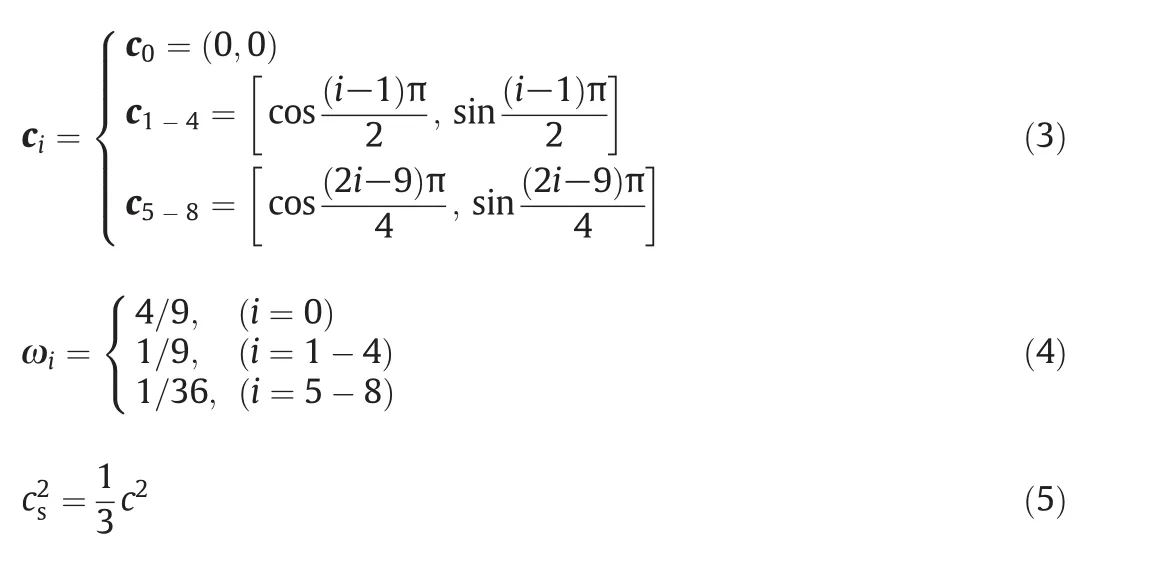
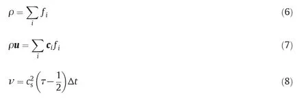
wherec=Δx/Δtis the lattice velocity,Δxis the lattice distance,and Δtis the evolution time step.And the macro variables,such as fluid density ρ,velocity u and the viscosity ν can be obtained from the following equations:
2.2.Shan–Chen model
In order to consider the interaction between fluid and the hydrophobic wall,a pseudo potential model,the Shan–Chen model is used,which can describe the short-range force interaction between different particles[31].It has been successfully used in simulating multiphase or multicomponent systems,a critical review can be referred to[32].
In a binary components system,the interaction force between components is.
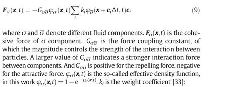
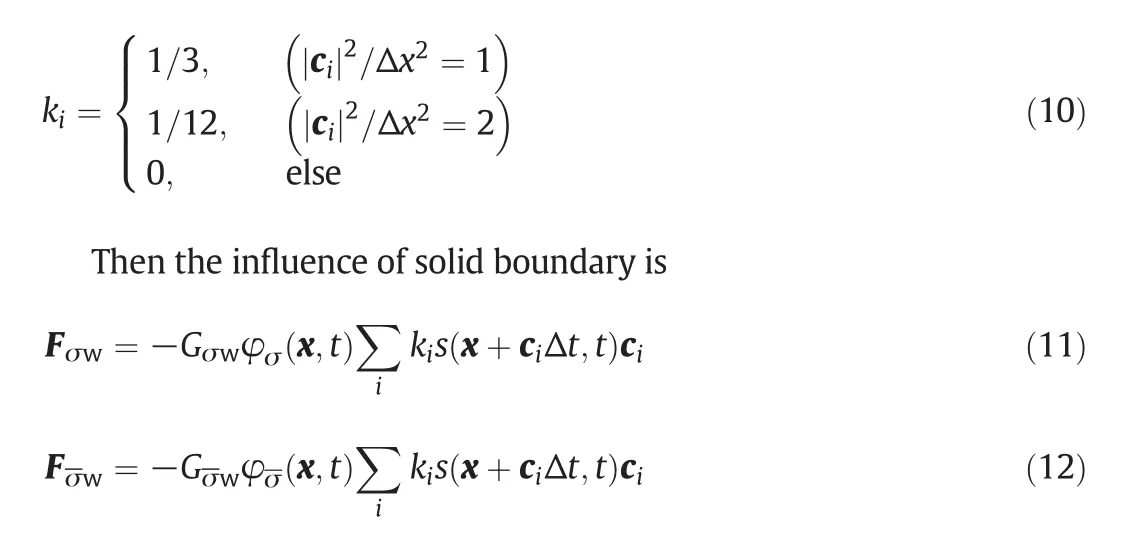
where Fσw(Fσw)andGσw(Gσw)denote the interaction force and the force coupling constant between solid wall and σ(σ)component.s(x+ciΔt,t)is an indicator function that is equal tos(x,t)=1−e−ρror 0 for a solid or a fluid domain node,respectively.ρris the density of solid wall.
Then according to Yang's equation,the contact angles of binary components system θ is a certain value which relates to θ(Gσσ,Gσw,Gσw,ρσ,ρσ).Thus,we can modify the magnitudes ofGσσ,GσwandGσwto simulate the flow systems with different wettability boundaries[34,35].

In this work,we apply Shan-Chen model in a single component system,in which the interaction force determines whether the surface will behave hydrophobic or hydrophilic for the liquid phase[36,37].The interaction force in single component system can be written as below:where Fl(Fw)andGl(Gw)denote the interaction forces and the force coupling constant between liquid–liquid(liquid-wall).As previously mentioned,φ(x,t)=1−e−ρ(x,t)ands(x,t)=1−e−ρrare for solid nodes,s(x,t)=0 for liquid nodes.In this paper,if there is no special explanation,ρralways equals 3ρ,which is in the range of the density ratios between some common solid materials and liquids.
These inter-particle forces cause an extra momentum change to the particles in each site.In the Shan–Chen model,a modified equilibrium state velocity in Eq.(2)is used to incorporate this momentum change in the dynamics of distribution functions[38]:
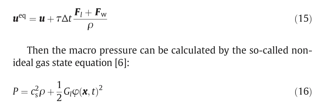
Which contains an ideal-gas contributioncs2ρ,and the second term in the rightside is the additional pressure caused by the particle interactions at each site.
The real macro velocity of fluid urealis defined as the average value of the local velocity before and after collision:

2.3.Boundary condition
In this work,a half-way bounce back boundary[39]is used to deal with the solid wall.The half-way bounce back boundary is a heuristic interpretation of no-slip boundary,which has a definite physical meaning:the fluid particles collide on the wall,then they propagate to the solid surface in the time of Δt/2,and in the following Δt/2,these particles are bounced back by the solid wall in the opposite direction.Thus,this process can be described as:

where ci+=−ci(ciis the direction towards the solid surface),xfindicates the node near the boundary,fi′(xf,t)is the distribution function after collision,andfi+(xf,t+Δt)is the distribution function after propagation(including the process of interacting with solid surface).
The non-equilibrium extrapolation scheme is used to deal with the pressure inlet and outlet.This boundary condition is proposed by Guoet al.[40],which divides the unknown distribution function on the boundary into two parts:equilibrium and non-equilibrium:

Here xbdenotes the boundary node.Then in the equilibrium term,for the pressure boundary condition,the densities on the boundary nodes are known,and the velocities are replaced by the fluid nodes near the boundary sites:

In addition,this method can ensure a fully developed inlet velocity if the simulation time is long enough.
3.Validation of Mathematical Model
In order to validate the built mathematical model and codes,a 2-D pressure-driven Poiseuille flow in the microchannel was simulated,and the results were compared to other reports.Here are some simulation parameters:the distance between two planes 2his 81 sites(ydirection),and the length of the flow regionLis 800 sites(xdirection).The value of driven pressure gradient on thexdirection is 0.0107.By changing the magnitude ofGlandGw,different hydrophobicity walls can be structured.It is worth noting that,all the geometry variables and fluid quantities are given in the lattice unit within certain ranges(e.g.,‖u‖<0.07,ρ~1,0≤Gw≤1.5),unless stated otherwise.Especially,in order to consider the influence of the hydrophobic wall only,the interaction parameter between liquid–liquidGlin our simulations was set to be a constant value,Gl=−0.1.
Typical velocity pro files of the simulation results in a hydrophobic microchannel(Gw=1.25)are displayed in Fig.1.The simulation results consist with the analytical results.At the same time,an evident boundary slip can be observed in it,which indicates the capability of this method to describe the boundary slip phenomenon.The density pro file is shown in Fig.2.We can find that due to the repulsion of solid surface,a low density layer appears near the wall.As with the enhancement of the hydrophobic property of the wall,the liquid density in the vicinity of the wall becomes smaller.It's worth noting that this low density layer emerges naturally from the simulation iteration,which may suggest the existence of‘nano-bubbles’[11].The bulk liquid slips in this low density region without direct contact with the solid wall,which may be the original reason for the boundary slip[6].
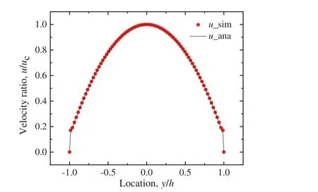
Fig.1.Axial velocity pro file(G w=1.25).X-coordinate is the dimensionless height,and y-coordinate is the dimensionless latitude velocity.u c is the latitude velocity of center.The dots(u_sim)are the simulation results in a hydrophobic microchannel(x=400).The line represents(u_ana)the analytical results.An obvious boundary slip can be observed.
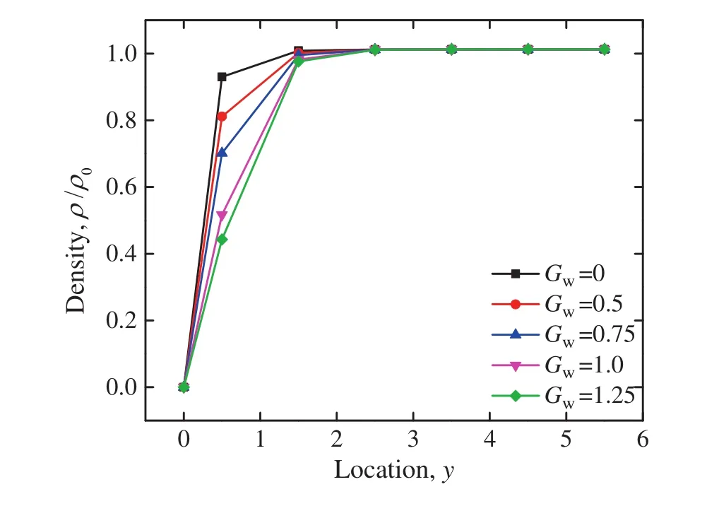
Fig.2.Density pro files in the y direction(ρ0 represents the density of outlet boundary,x=400).
The slip length in this microchannel is calculated by Naiver's slip boundary definition[41],based on the conception that the velocity in flow direction in Poiseuille flow is in the form of:

Then we can obtain the value of slip length from our calculation velocity pro files by a least square fit with Eq.(22).After that,the influence of the bulk density,the wetting property of wall and the microchannel diameter on the slip length are systematically investigated.The slip length decreases with the increase of the bulk pressure,and increases with the increase ofGw.In addition,although the diameter of the pipe has an impact on the slip length,compared to the other two parameters,its influence is much smaller.Remarkably,although the slip length is almost unchanged while the diameter of microchannel increases,from Eq.(23)we can know that the effect of boundary slip on the mass flux is gradually reduced.That means if the pipe is large enough,the influence of boundary slip can be ignored.All these results are in agreement with other reports[11,24],which verifies the correctness of our mathematical model and codes.
2.3.2 HPLC法测定PTX含量 色谱条件同“2.2.2(2)”项下。取PTX配制成2、5、10、15、20 μg/mL的溶液,进样,计算在此范围内质量浓度和峰面积。线性方程为Y=1 987.3 X+4.515 1,r2=1.000 0。表明PTX在2~20 μg/mL线性关系良好。样品预处理:12 000 r/min转速离心5 min,取上清液进样。
4.Results and Discussion
4.1.Variable-section microchannel simulation
Our verified codes are extended to simulate a hydrophobic microchannel with specific shape as shown in Fig.3.This microchannel includes three parts:the entrance sectionL1,the transition sectionL2and the exit sectionL3.The height of entrance is 2R1and the height of exit is 2R2.As in the Poiseuille flow,the fluid in the nozzle is driven by the pressure drop ΔPbetween inlet and outlet.Different hydrophobic properties of solid surface are constructed by changingGw.In this part,we will simulate a series of microchannels with different transition lengths and surface properties,so as to investigate the influence of boundary slip on the mass flux.
Some detailed simulation parameters are listed in Table 1.The simulation results are showed in Fig.4.In hydrophilic microchannel(Gw=0),there is an increase in the mass flux when the length of the transition section is increased.However,under the hydrophobic condition(Gw>0),as the length of the transition section increases,the mass flux in the microchannel first decreases but then increases.

Fig.3.Simulation domination.

Table 1Simulation parameters(all these geometry parameters are in the dimensionless form based on R1)
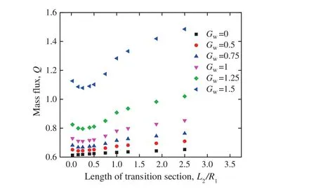
Fig.4.The relationship between mass flux and length of transition section(simulation results of Table 1).
In order to explain the variation of mass flux in Fig.4,detailed streamlines are displayed in Fig.5,from which we can observe that,the flow state is always kept in a laminar flow pattern in the hydrophilic microchannel.Therefore,with the increase ofL2,the average channel width increases,which will cause the increase of mass flux in the microchannel.Then in the hydrophobic condition,in Fig.5(a)there are two eddies formed in the transition section,which can significantly decrease the mass flux.That is the reason why the increase ofL2makesQdecrease first.In Fig.5(b)and(c),the flow pattern turns into laminar flow,then a longer transition section is beneficial for mass flux.And we discover that,while α=45°,the vortexes disappear,the mass flux is approximately equal to the orthogonal transition condition.Thus,a qualitative conclusion can be made:for the purpose of obtaining a larger mass flux in hydrophilic microchannel,a longer transition section is needed;but in hydrophobic microchannel,an orthogonal(α=90°)or sufficiently long transition section(α ≥ 45°)is better.
It is noteworthy that although the Reynolds number in Fig.5(a)is quite small(about 3.4),there are still two vortexes formed in the flow.This abnormal phenomenon was also mentioned in the MD simulation[15].In addition,Fig.5(c)indicates that the streamlines in the hydrophobic microchannel are quite different from those in the hydrophilic one,especially in the transition section,the streamlines in the bulk liquid have also been influenced.In fact,under the repulsive force of the tilted wall,a higher pressure area is formed in the center of the transition section,leading the streams bend to the wall.
To describe the slip phenomenon in this microchannel,an average slip length is defined,which is calculated by taking the average of the slip length in the mid of inlet and outlet sections.Since in this situation the slip length is mainly influenced by the wetting property of wall and the density of the bulk liquid,the slip length in the upstream and downstream was kept nearly the same in our simulation situation.In fact,we calculated them in each working condition,and the results verified our statement.
The slip length in the downstream is a bit larger than in the upstream,but the difference between them is no more than 4%.Then the relationships between mass flux and slip length in this variablesection microchannel are shown in Fig.6.As Fig.6 implies,the boundary slip is helpful to linearly increase the mass flux in this complex-shaped microchannel,similar to that in the straight channel.
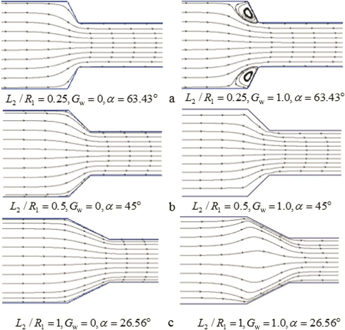
Fig.5.Streamlines in the transition zone.
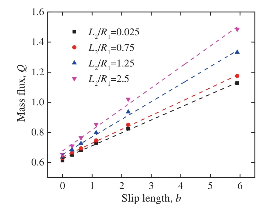
Fig.6.The relationship between mass flux Q and average slip length b.
4.2.Simulation of complex surface wettability of microchannel
A novel microchannel design that uses different hydrophobic properties of wall surface at different stages of the channel will be simulated in this section.Firstly,we will simulate a straight channel,and the influence of the length of hydrophobic segment on the mass flux is to be studied.The height of this straight microchannel is 2h=81,the total length isL=800,including hydrophilic(Lw)and hydrophobic(Ln)parts.
The velocity pro files(in thexdirection)and streamlines are shown in Fig.7.The simulation results are qualitatively similar to the MD simulation results[18].It is clear that the maximum velocity in the hydrophilic section is larger than that in the hydrophobic section.The reason is that the mass flux at each section is equal,but in the non wetting section,the boundary slip will lead to an increase of the liquid velocity near the wall,causing a decrease of the velocity of liquid at the center.
The relationships between length of hydrophobic surface and mass flux are shown in Fig.8.The simulation data indicates that the mass flux depends linearly on the length of hydrophobic surface.Then the mass flux in such a surface property mixed channel can be derived from Eq.(23)easily:

On the other hand,the frequency of surface wettability switching has been investigated.For simplicity,we consider the situation asLn=Lw.And the simulation setting and results are shown in Fig.9,from which we can conclude that a high frequency will cause a marginal reduction in the mass flux.
We also extend this mixed design into variable-section microchannel by separating the micro channel with complex geometry in Fig.3 into three sections and changing the hydrophobicity of each channel respectively.To explain the simulation conditions more visually,we use a parameterato describe the wettability of the surface:when the wall is hydrophobica=1,anda=0 in the condition of hydrophilic wall.So the wettability nature of the channel could be described by a combination of three parameters ofa.For example,101 means a microchannel with hydrophobic import and export section,but a hydrophilic transition section.There are eight kinds of combinations here in our simulation:000,001,010,011,100,101,110,and 111.All these combinations have been simulated,and the definite parameters are listed in Table 2.
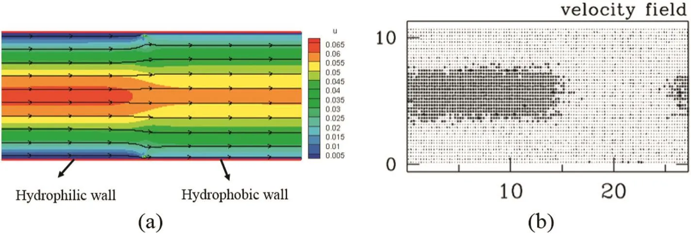
Fig.7.Velocity pro files comparison between LBM(a)and MD(b)simulations[18].(In the right picture,a darker color represents a larger velocity than the average speed at the center point of the system).
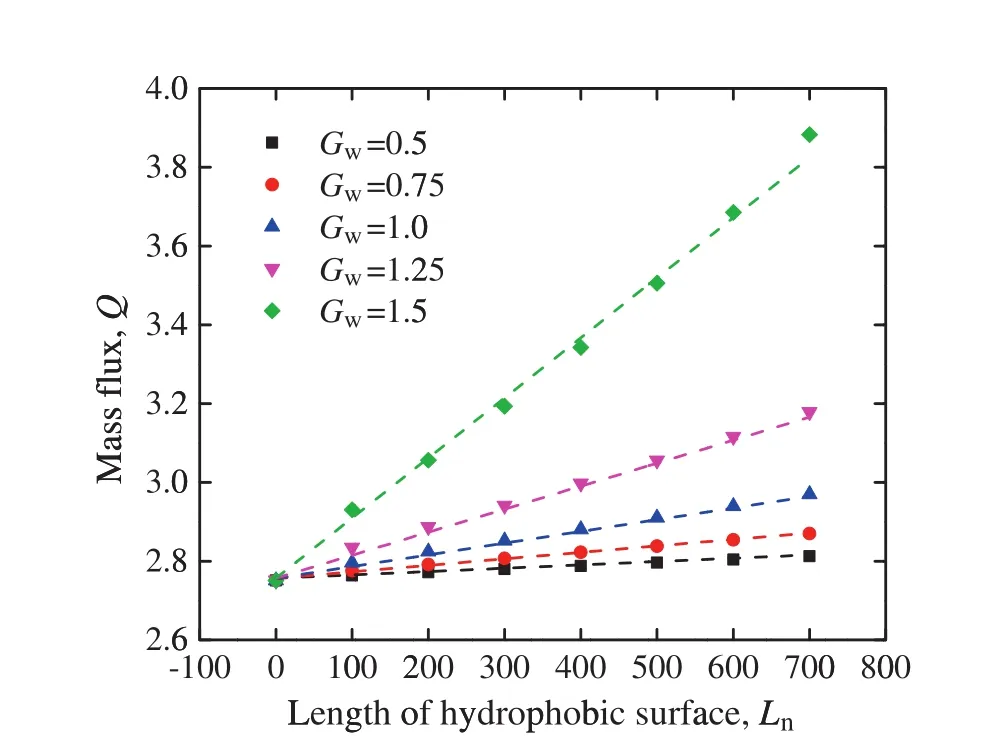
Fig.8.The relationship between the length of hydrophobic surface and the mass flux in a straight microchannel.(The dots are the simulation results and the dash lines are the calculation results of Eq.(24)).

Table 2Simulation parameters of complex-shaped microchannel while considering the effect of different surface wettability combinations.(The geometry parameters are all in the dimensionless form based on R1)
As shown in Fig.10,the wetting property of upstream section has little influence on the mass flux,the wetting property of downstream section has significant influence on the mass flux,and the effect of transition section is in between.On the whole,through the analysis of the overall trend,more sections with hydrophobic surface are beneficial to the mass flux.
5.Conclusions
We built up a pseudo potential LBM to describe the wettability of microchannel surface and simulated the flow process in microchannels with variable-section and surface property.Some conclusions are as follows:
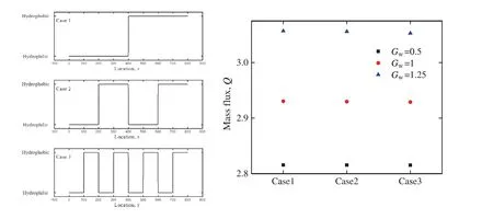
Fig.9.Different surface wettability alternative frequency setting(left)and the simulation results(right).
(1)The hydrophobic surface mainly has two effects on the liquid flow in a variable-section microchannel.On the one hand,the boundary slip caused by the repulsive force of wall increases the mass flux linearly.On the other,the hydrophobic surface influences the flow pattern.
(2)In a straight microchannel with different wetting property surfaces,a linearly relationship can be found between hydrophobic surface length and mass flux,and the surface wettability alternative frequency has little effect on the mass flux.In addition,more hydrophobic sections also have benefit for the mass flux in the variable-section microchannel.
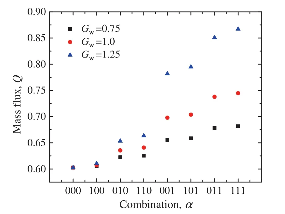
Fig.10.The mass flux in different combination microchannels with complex-shapes.
Acknowledgements
Jiangsu National Synergetic Innovation Center for Advanced Materials is gratefully acknowledged.
[1]G.M.Whitesides,The origins and the future of micro fluidics,Nature442(7101)(2006)368–373.
[2]C.Neto,D.R.Evans,E.Bonaccurso,H.-J.Butt,V.S.Craig,Boundary slip in Newtonian liquids:A review of experimental studies,Rep.Prog.Phys.68(12)(2005)2859.
[3]K.Watanabe,Y.Udagawa,H.Udagawa,Drag reduction of Newtonian fluid in a circular pipe with a highly water-repellent wall,J.Fluid Mech.381(1999)225–238.
[4]J.P.Rothstein,Slip on superhydrophobic surfaces,Annu.Rev.Fluid Mech.42(2010)89–109.
[5]D.R.Reyes,D.Iossifidis,P.-A.Auroux,A.Manz,Micro total analysis systems.1.Introduction,theory,and technology,Anal.Chem.74(12)(2002)2623–2636.
[6]R.Benzi,L.Biferale,M.Sbragaglia,S.Succi,F.Toschi,Mesoscopic two-phase model for describing apparent slip in micro-channel flows,EPL(Europhys.Lett.)74(4)(2006)651.
[7]D.C.Tretheway,C.D.Meinhart,Apparent fluid slip at hydrophobic microchannel walls,Phys.Fluids14(3)(2002)L9–L12.
[8]M.Asfer,P.K.Panigrahi,Boundary Slip of Liquids,in Encyclopedia of Micro fluidics and Nano fluidics,Springer,2014 1–12.
[9]P.Joseph,P.Tabeling,Direct measurement of the apparent slip length,Phys.Rev.E71(3)(2005)035303.
[10]J.Koplik,J.R.Banavar,J.F.Willemsen,Molecular dynamics of fluid flow at solid surfaces,Phys.Fluids A Fluid Dyn.1(5)(1989)781–794.
[11]Y.-Y.Chen,H.-H.Yi,H.-B.Li,Boundary slip and surface interaction:A lattice Boltzmann simulation,Chin.Phys.Lett.25(1)(2008)184.
[12]J.-T.Cheng,N.Giordano,Fluid flow through nanometer-scale channels,Phys.Rev.E65(3)(2002)031206.
[13]J.S.Lee,G.H.Gu,H.Kim,K.S.Jeong,J.Bae,J.S.Suh,Growth of carbon nanotubes on anodic aluminum oxide templates:Fabrication of a tube-in-tube and linearly joined tube,Chem.Mater.13(7)(2001)2387–2391.
[14]H.-C.Wu,W.-S.Hwang,H.-J.Lin,Development of a three-dimensional simulation system for micro-inkjet and its experimental verification,Mater.Sci.Eng.A373(1)(2004)268–278.
[15]X.-J.Fan,N.Phan-Thien,N.T.Yong,X.Diao,Molecular dynamics simulation of a liquid in a complex nano channel flow,Phys.Fluids14(3)(2002)1146–1153.
[16]I.Hanasaki,A.Nakatani,Water flow through carbon nanotube junctions as molecular convergent nozzles,Nanotechnology17(11)(2006)2794.
[17]L.Guo,S.Chen,M.O.Robbins,Slip boundary conditions over curved surfaces,Phys.Rev.E93(1)(2016)013105.
[18]M.Cieplak,J.Koplik,J.R.Banavar,Nanoscale fluid flows in the vicinity of patterned surfaces,Phys.Rev.Lett.96(11)(2006)114502.
[19]D.Byun,V.dat Nyugen,J.Kim,H.S.Ko,Free surface transition and momentum augmentation of liquid flow in micro/nano-scale channels with hydrophobic and hydrophilic surfaces,J.Mech.Sci.Technol.22(12)(2008)2554–2562.
[20]Y.Gogotsi,J.A.Libera,A.Güvenç-Yazicioglu,C.M.Megaridis,In situ multiphase fluid experiments in hydrothermal carbon nanotubes,Appl.Phys.Lett.79(7)(2001)1021–1023.
[21]R.W.Johnson,Handbook of Fluid Dynamics,CRC Press,USA,1998.
[22]B.-Y.Cao,J.Sun,M.Chen,Z.-Y.Guo,Molecular momentum transport at fluid–solid interfaces in MEMS/NEMS:A review,Int.J.Mol.Sci.10(11)(2009)4638–4706.
[23]J.Horbach,S.Succi,Lattice Boltzmann versus molecular dynamics simulation of nanoscale hydrodynamic flows,Phys.Rev.Lett.96(22)(2006)224503.
[24]J.Harting,C.Kunert,H.J.Herrmann,Lattice Boltzmann simulations of apparent slip in hydrophobic microchannels,EPL(Europhys.Lett.)75(2)(2006)328.
[25]C.Kunert,J.Harting,On the effect of surfactant adsorption and viscosity change on apparent slip in hydrophobic microchannels,Prog.Comput.Fluid Dyn.Int.J.8(1–4)(2008)197–205.
[26]L.Zhu,D.Tretheway,L.Petzold,C.Meinhart,Simulation of fluid slip at3Dhydrophobic microchannel walls by the lattice Boltzmann method,J.Comput.Phys.202(1)(2005)181–195.
[27]R.-L.Zhang,Q.-F.Di,X.-L.Wang,W.-P.Ding,G.Wei,Numerical study of the relationship between apparent slip length and contact angle by lattice Boltzmann method,J.Hydrodyn.B24(4)(2012)535–540.
[28]C.Kunert,J.Harting,Simulation of fluid flow in hydrophobic rough microchannels,Int.J.Comput.Fluid Dyn.22(7)(2008)475–480.
[29]X.He,S.Chen,G.D.Doolen,A novel thermal model for the lattice Boltzmann method in incompressible limit,J.Comput.Phys.146(1)(1998)282–300.
[30]Y.Qian,D.d'Humières,P.Lallemand,Lattice BGK models for Navier–Stokes equation,EPL(Europhys.Lett.)17(6)(1992)479.
[31]D.T.Thorne,Lattice Boltzmann Modeling:An Introduction for Geoscientists and Engineers,Springer,2006.
[32]L.Chen,Q.Kang,Y.Mu,Y.-L.He,W.-Q.Tao,A critical review of the pseudopotential multiphase lattice Boltzmann model:Methods and applications,Int.J.Heat Mass Transf.76(2014)210–236.
[33]X.Shan,Analysis and reduction of the spurious current in a class of multiphase lattice Boltzmann models,Phys.Rev.E73(4)(2006)047701.
[34]R.Benzi,L.Biferale,M.Sbragaglia,S.Succi,F.Toschi,Mesoscopic modeling of a two-phase flow in the presence of boundaries:The contact angle,Phys.Rev.E74(2)(2006)021508.
[35]H.Huang,D.T.Thorne,M.G.Schaap,M.C.Sukop,Proposed approximation for contact angles in Shan-and-Chen-type multicomponent multiphase lattice Boltzmann models,Phys.Rev.E76(6)(2007)066701.
[36]J.Harting,C.Kunert,J.Hyvaluoma,Lattice Boltzmann simulations in micro fluidics:Probing the no-slip boundary condition in hydrophobic,rough,and surface nanobubble laden microchannels,Microfluid.Nanofluid.8(1)(2010)1–10.
[37]S.Schmieschek,Computer simulation of boundary effects and multiphase flows on the mesoscopic scale,Technische Universiteit,Eindhoven,2015.
[38]X.Shan,G.Doolen,Multicomponent lattice-Boltzmann model with inter particle interaction,J.Stat.Phys.81(1–2)(1995)379–393.
[39]D.P.Ziegler,Boundary conditions for lattice Boltzmann simulations,J.Stat.Phys.71(5–6)(1993)1171–1177.
[40]Z.-L.Guo,C.-G.Zheng,B.-C.Shi,Non-equilibrium extrapolation method for velocity and pressure boundary conditions in the lattice Boltzmann method,Chin.Phys.11(4)(2002)366.
[41]C.Navier,Memoirs de l'Academie Royale Des Sciences de l'Institut de France,vol.1,Royale des Sciences de l'Institut de France,1823.
猜你喜欢
杂志排行
Chinese Journal of Chemical Engineering的其它文章
- Suppressing secondary reactions of coal pyrolysis by reducing pressure and mounting internals in fixed-bed reactor☆
- Transformation mechanism of nutrient elements in the process of biochar preparation for returning biochar to soil☆
- Preparation of cross-linked enzyme aggregates of nitrile hydratase ES-NHT-118 from E.coli by macromolecular cross-linking agent☆
- Development of a new cleaner production process for cassava ethanol☆
- Multi-objective regulation in autohydrolysis process of corn stover by liquid hot water pretreatment
- Modelling of adsorption of textile dyes over multi-walled carbon nanotubes:Equilibrium and kinetic
