Side force controlon slender body by self-excited oscillation flag
2016-12-24JinZhiWeiweiZhngChunqingGoYnhuZhngZhengyinYeHunlingWng
Jin Zhi,Weiwei Zhng,∗,Chunqing Go,Ynhu Zhng,Zhengyin Ye, Hunling Wng
aNationalKey Laboratory ofAerodynamic Design and Research,Northwestern PolytechnicalUniversity,Xi'an 710072,China
bAeronautics and Astronautics Engineering Institute,Air Force Engineering University,Xi'an 710038,China
Letter
Side force controlon slender body by self-excited oscillation flag
Jian Zhaia,Weiwei Zhanga,∗,Chuanqiang Gaoa,Yanhua Zhangb,Zhengyin Yea, Huanling Wanga
aNationalKey Laboratory ofAerodynamic Design and Research,Northwestern PolytechnicalUniversity,Xi'an 710072,China
bAeronautics and Astronautics Engineering Institute,Air Force Engineering University,Xi'an 710038,China
A R T I C L E I N F O
Article history:
Received in revised form
4 July 2016
Accepted 7 August 2016
Available online 28 August 2016
Self-excited oscillation flag Slender body High angle ofattack Proportionalcontrol Side force
Strong asymmetricalvortices appear on the leeward of slender body at high angles of attack,which has very unfavorable effect on the stability and controlofthe aircraft.A method is developed to control the side force of slender body at high angles ofattack,and is verified in wind tunnel.A thin-film triangular self-excited oscillation flag is fixed at the tip of the slender body model whose semi-apex angle is 10°. Side force is approximately linearly proportional to roll-setting angle of self-excited oscillation flag at high angles of attack,and the slop of fitting straight line obtained by the least square method is−0.158. The linear relationship between side force and roll-setting angle provides convenience for developing side force control law of slender body at high angles of attack.Experimental data shows that the side force coefficients vary linearly with roll-setting angles when a specific plastic self-excited oscillation flag is used as the control flag.The range of side force coefficient and roll-setting angle are,respectively,−3.2 to 3.0 and−20°to 20°.The device is simple,effective,and is ofgreatpotentialin engineering application.
©2016 The Authors.Published by Elsevier Ltd on behalfof The Chinese Society of Theoreticaland Applied Mechanics.This is an open access article under the CC BY-NC-ND license(http:// creativecommons.org/licenses/by-nc-nd/4.0/).
In order to obtain high maneuverability and agility,the modern fighter and tactical missile need to have excellent aerodynamic characteristics at high angles of attack.However,for the aircraft with a slender forebody,a multiple asymmetric vortices structure composed of a main vortex,secondary vortex,and tertiary vortex will be produced on the leeward[1].Even at zero sideslip angle,asymmetric vortices will induce large side force and yaw moment,and cause very unfavorable influence on the aerodynamic,stability,and controlcharacteristics ofaircraft[2].
Experimental and numerical methods have found that at high angles of attack,the symmetric vortices were very sensitive to the disturbance on the tip[3].The micro-disturbance has a significant effect of the spatial distribution of the leeward vortices of slender body.Based on the above ideas,a variety ofmethods to controlthe side force of the slender body at high angles of attack are developed.These methods can be divided into active control and passive control methods.Active controlmethod requires continuous energy input,while passive controlmethod does not require.
固定矿浆pH为11.5±0.2,淀粉用量为100 mg/L,CaCl2用量为100 mg/L,两种捕收剂不同用量对三种矿物的浮选结果如图6所示。
Active control techniques include steady jet blowing,single dielectric barrier discharge(SDBD)plasma actuators,and oscillating micro tip strake.
Bernhardtand Williams[4]applied jetblowing technique near the tip of the forebody to control the development of asymmetric vortices.Vortex position varies continuously when the control input is atα=45°,which is consistent with a convective type of instability.Thus,proportional control of the side force can be achieved.However,this process is not feasible under the condition α=55°,wherein bistable modes dominate.
Based on this study,many researchers established that the side force may respond to dynamic alternating excitations continuously.Liu et al.[5]replaced the blowing nozzles with a pair of SDBD plasma actuators to control asymmetric vortices.Ming and Gu[6]developed an oscillating micro tip strake to control asymmetric vortices.
Passive control techniques include nose strakes,boundarylayer transition strips,and nose boom,etc.Nose strakes and boundary-layer transition strips decrease the relative magnitude of the side force by suppressing the input sensitivity of the tip.Nose boom reduces the side force by inducing vortices.Malcolm[7]discussed various passive controltechniques and expounded on their effectiveness and limitations.Ma et al.[8]also indicated that the original uncertain asymmetric flow would be transformed into a deterministic asymmetric flow if a small artificial perturbation is added at the tip.
Zhang etal.[9,10]recently developed two passive dynamic control techniques,namely,self-excited oscillation flag and vortexgenerators fixed on the tip of the slender body.A thin-film flag[9] flutters when the free-steam velocity exceeds the critical speed. Thus,the dynamic excitation provided by the fluttering of the flag can transformthe bistable flow state from asymmetric to symmetric at high angles of attack;the corresponding side force then decreases significantly.In Ref.[10],the vortices induced by vortex generators break down within the range ofexperimentalangles of attack.Unsteady excitation of the breakdown of vortices controls the leeward asymmetric vortices of the slender body.Experimentalresults indicated thatthe side force changes monotonously with the setting angles of the vortex generators.

Fig.1.Sketch of slender body and self-excited oscillation flag.

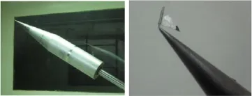
Fig.2.Photographs of slender body and self-excited oscillation flag fixed in wind tunnel.
In Ref.[9],the self-excited oscillation flag can controlthe spatial distribution of the asymmetric vortex of the slender body at high angles of attack.But,it can only suppress the side force of the slender body.
This paper is a continuation of the previous work of Ref.[9]. The wind tunnelexperiment is used to study the possibility of the linear controlofthe side force ofthe slender body under the high angles of attack by the self-excited oscillation flag.
Wind tunnelexperimentwas completed in the low speed wind tunnel at Air Force Engineering University.The test section is a rectangle(1.2 m X1.0 m X1.5 m),range of velocity of test section is 5-75 m/s,the turbulence intensity is 0.2%.Used a six component strain gauge measuring force balance,whose accuracy is 0.1%to 0.2%,to testing;sampling frequency of balance is 50 Hz during 1 s, sampling data average is force test results.The variation range of angles of attack is 27.5°to 55°,the accuracy is±3′.
The slender body model is designed according to Ref.[11], which is a conical cylinder combination,as shown in Fig.1. The length of model is 600 mm,diameter of the bottom of the cylindrical section is 100 mm,conical section slenderness ratio is 3,semi-apex angle is 10°.The model is divided into three parts: steelconicalsection,transition section,and the cylinder section of aluminum.The tip of the nose has a hole whose diameter is 1 mm, for the installation of the rod of self-excited oscillation flag.θis angle of rolling the slender body,θfis the angle of rolling the flag, as shown in Fig.1.
The thin film righttriangle flags were made offlexible material. The flag rod is bent.Figure 2 shows the photograph ofslender body fixed in wind tunnel and self-excited oscillation flag mounted to the slender body model.
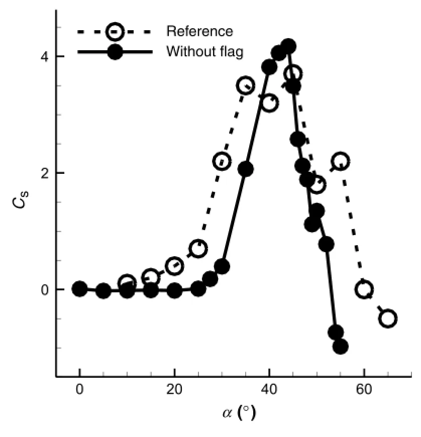
Figure 3 shows the side force coefficient changes with the angle ofattack when the wind speed is 15 m/s.From the figure,we can see the results obtained by the experiment are basically consistent with Ref.[11].When the angle of attack is 45°,the side force reaches the maximum value.

Fig.3.Side force coefficient of bareheaded slender body changes with angles of attack.

Fig.4.Side force coefficient of bareheaded slender body changes with rollangles (α=45°).
Figure 4 shows the side force coefficient changes with roll angle when the angle of attack is 45°.From the figure,we can see that the value of the coefficient of side force jumps between the two''extreme'',indicating that the slender body has in the global instability of the bistable mode,slender vortices can only switch between the two stable states.
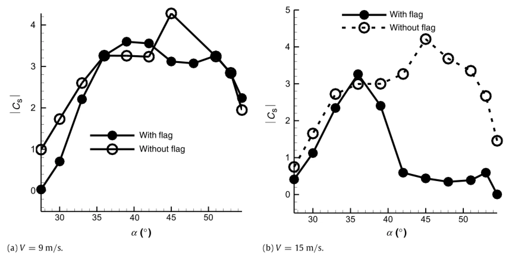
Figure 5 shows the absolute value of the side force coefficient changes with the angle ofattack.When the wind speed is 9 m/s,thevalue ofside force ofslender body with and withoutflag is basically the same,as shown in Fig.5(a).This is because the flag does not flutter,cannot produce unsteady wake and cannot influence the leeward vortices distribution of slender body basically.However, when the velocity is 15 m/s,the absolute value of side force of slender body with self-excited oscillation flag will decrease to 0 after the angle of attack more than 36°,as shown in Fig.5(b).It indicates thatthe side force has been eliminated,and slender body asymmetric vortices change to symmetric vortices.

Fig.5.The absolute value of side force coefficient changes with angles of attack.

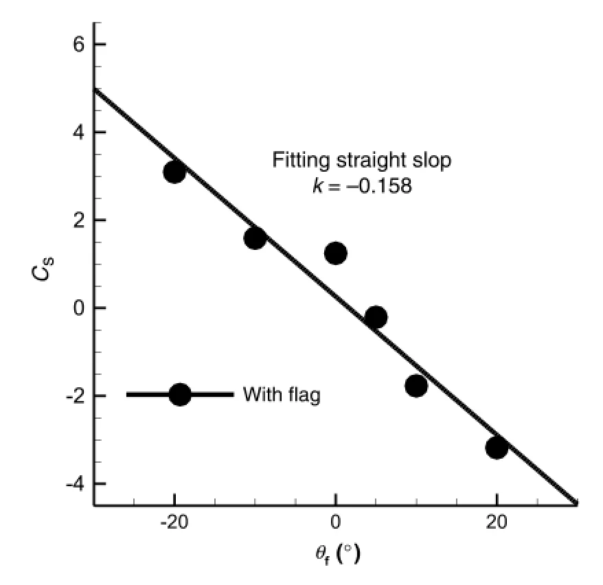
Fig.6.Side force coefficients change with roll setting angles of the flag and fitting line.
Figure 6 shows the side force coefficient changes with the roll angle of the flag.When the angle of attack is 45°,wind speed is 15 m/s,and the range of rollangle is−20°to 20°,the side force of slender body changes approximately linearly with the rollangle of flag.The linearslope obtained by the leastsquare fitting method is−0.158,which provides a great convenience for the design of the side force control law under the high angles of attack,side force coefficient amplitude range is−3.2 to 3.Compared with Fig.6,the absolute value of side force of slender body without flag does not change with the same roll angle range(−20°to 20°).This shows that the flag can be used to control the side force of slender body at high angles of attack.The unsteady wake of the flag is the key factor in the control of slender body.
In this paper,a new method to control the side force of slender body at high angles of attack is developed,and the effect of this method is verified by the wind tunnel experiments.The results indicate the following.
(1)When the angle of attack is 45°,the side force of the slender body is the largest and the asymmetricalleeward vortex enters into the bistable state.
(2)The unsteady wake is the key to controlthe spatialdistribution of the leeward vortex in the slender body.
(3)The side force of slender body changes approximately linearly with the roll angle of the flag.The slope of the fitting line obtained by the least square method is−0.158,this linear relationship provides great convenience for design side force controllaw ofslender body at high angles ofattack.
This experiment is a preliminary study,the next flow field display and related numerical simulation work will further reveal the mechanism of side force control of the self-excited oscillation flag.
Acknowledgment
The project was supported by the''National Natural Science Foundation-Outstanding Youth Foundation''.
[1]G.Wang,G.H.Li,X.G.Liang,et al.,Evolution mechanism for wake-type flow over slender body,Eng.Mech.24(2007)25-30.
[2]J.S.Cai,H.M.Tsai,S.J.Luo,Design of optimalwing-body configuration to delay onsetofvortex asymmetry,AIAA J.49(2011)164-171.
[3]B.F.Ma,X.Y.Deng,Tip-disturbance effects on asymmetric vortex breakdown around a chined forebody,J.Aircr.45(2008)1098-1104.
[4]J.E.Bernhardt,D.R.Williams,Proportional control of asymmetric forebody vortices,AIAA J.36(1998)2087-2093.
[5]F.Liu,S.J.Luo,C.Gao,Flow controlover a conicalforebody using duty-period plasma actuators,AIAA J.46(2008)2969-2973.
[6]X.Ming,Y.S.Gu,Flow controland mechanism for slender body at high angle ofattack,Modern Phys.Lett.B 19(2005)1571-1574.
[7]G.Malcolm,Forebody vortex control:a progress review,AIAA Paper 93-3540, Aug.1993.
[8]B.F.Ma,X.Y.Deng,Y.Chen,Effects offorced asymmetric transition on vortex asymmetry around slender bodies,AIAA J.45(2007)2671-2676.
[9]W.W.Zhang,X.B.Liu,J.Zhai,Experimentalstudy on side force alleviation of conicalforebody with a fluttering flag,Phys.Fluids 24(2012)124105.
[10]J.Zhai,W.W.Zhang,C.Q.Gao,etal.,Side force controlon slenderbody by vortex generators,Chin.J.Theor.Appl.Mech.46(2014)308-312.
[11]V.J.Modi,T.Ries,A.Kwan,Aerodynamics of pointed forebodies at high angles ofattack,J.Aircr.21(1984)428-443.
∗Corresponding author.
E-mail address:aeroelastic@nwpu.edu.cn(W.Zhang).
http://dx.doi.org/10.1016/j.taml.2016.08.004
2095-0349/©2016 The Authors.Published by Elsevier Ltd on behalfof The Chinese Society of Theoreticaland Applied Mechanics.This is an open access article under the CC BY-NC-ND license(http://creativecommons.org/licenses/by-nc-nd/4.0/).
猜你喜欢
杂志排行
Theoretical & Applied Mechanics Letters的其它文章
- Two-dimensionalmodeling of the self-limiting oxidation in silicon and tungsten nanowires
- Subset-based localvs.finite element-based globaldigitalimage correlation:A comparison study
- Magnetic induction strength on surface of a ferro-medium circular cylinder
- Numericalinvestigation of unsteady mixing mechanism in plate film cooling
- High temperature effects in moving shock reflection with protruding Mach stem
- The Richtmyer-Meshkov instability of a'V'shaped air/helium interface subjected to a weak shock
