Mechanics of bioinspired imaging systems
2016-12-09ZhengweiLiYuWangJianliangXiao
Zhengwei Li,Yu Wang,Jianliang Xiao
Department of Mechanical Engineering,University of Colorado Boulder,Boulder,CO 80309,USA
Review
Mechanics of bioinspired imaging systems
Zhengwei Li,Yu Wang,Jianliang Xiao∗
Department of Mechanical Engineering,University of Colorado Boulder,Boulder,CO 80309,USA
H I G H L I G H T S
•Two types of bioinspired imaging systems,i.e.tunable electronic eyeball cameras and artificial compound eye cameras,are introduced.
•Recent progresses in mechanics of these bioinspired imaging systems are reviewed.
•The impact of mechanics on related systems and future development of curvilinear optoelectronics are discussed.
A R T I C L EI N F O
Article history:
Accepted 26 November 2015
Available online 23 December 2015
Mechanics
Bioinspired imaging system
Eyeball camera
Compound eye camera
Stretchable electronics
Imaging systems in nature have attracted a lot of research interest due to their superior optical and imaging characteristics.Recent advancements in materials science,mechanics,and stretchable electronics have led to successful development of bioinspired cameras that resemble the structures and functions of biological light-sensing organs.In this review,we discuss some recent progresses in mechanics of bioinspired imaging systems,including tunable hemispherical eyeball camera and artificial compound eye camera.The mechanics models and results reviewed in this article can provide efficient tools for design and optimization of such systems,as well as other related optoelectronic systems that combine rigid elements with soft substrates.
©2015 The Authors.Published by Elsevier Ltd on behalf of The Chinese Society of Theoretical and Applied Mechanics.This is an open access article under the CC BY-NC-ND license(http://
creativecommons.org/licenses/by-nc-nd/4.0/).
Contents
1.Introduction........................................................................................................................................................................................................................11
2.Mechanics of tunable hemispherical eyeball camera......................................................................................................................................................12
2.1.Mechanics of tunable lens.....................................................................................................................................................................................12
2.2.Mechanics of tunable detector..............................................................................................................................................................................13
3.Mechanics of artificial compound eye camera.................................................................................................................................................................15
3.1.Mechanics of geometrical transformation of the compound eye camera.........................................................................................................16
3.2.Mechanics and optics of stretchable elastomeric microlenses...........................................................................................................................18
4.Conclusion and discussion.................................................................................................................................................................................................19
Acknowledgments.............................................................................................................................................................................................................20
References...........................................................................................................................................................................................................................20
1.Introduction
Evolution has created remarkable imaging systems with many attractive attributes[1–4].For example,human eyes use simple optics to collect light rays from the environment and focus them onto a hemispherical retina to form sharp images[5,6].This type of imaging system has the advantage of optimal photonic usage in order to guarantee maximum light sensitivity and high spatial resolution[1,2].Another type of imaging system is compound eyes that are commonly found in arthropods.A compound eye is usually composed of hundreds or thousands of individual units, i.e.ommatidia,on a curved surface.Each ommatidium has its own optical lens and light detector for imaging purpose[5].Such structures of compound eyes,although cause reduced resolutions, can provide very wide field of view angle,low aberration,high sensitivity to motion and infinite depth of field[7–9].
Due to their remarkable characteristics,bioinspired imaging devices have great potential in medical,industrial and military applications[10,11].However,almost all biological eyes adopt curvilinear imagers[11],which does not comply with established optoelectronic systems that are hard,rigid and planar,owning tothe inherent 2D nature of established materials processing technologies and intrinsic brittle nature of inorganic semiconductor materials[12–14].This mismatch in mechanics and forms greatly hinders the development of bioinspired digital cameras,with photodetector arrays wrapped onto curvilinear surfaces in order to achieve imaging performances comparable to biological counterparts.
Thanks to the progress of stretchable electronics,researchers havesuccessfullyrealizedcurvilinearoptoelectronics[15–24].Mechanical stretchability and flexibility have been introduced into otherwise rigid and brittle optoelectronic systems by utilizing advanced mechanics principles and structural designs,so that photodetector arrays can be wrapped onto curvilinear surfaces without noticeably affecting their operating performance[25–31]. For example,Ko et al.[25]developed a fully functional hemispherical electronic eyeball camera that mimics the structure and function of human eye.In this work,silicon photodetectors were connected by buckled,stretchable interconnects to form a mesh layout,such that mechanical stretchability of the array is achieved. This layout of photodetectors was first fabricated in planar geometry,by using established semiconductor processing steps,and then transformed into hemispherical shape to resemble the geometry of retina in human eyes.Impressive imaging capability has been demonstrated with a simple plano-convex lens.
One drawback of this imaging design,adopted by both the electronic eyeball cameras and human eyes,is that the detector curvature is fixed.However,some recent progresses in optoelectronics require dynamically tunable optical properties in a controllable manner.Different tuning mechanisms,such as strain [32,33],hydraulics[34,35],stimuli-responsive hydrogels[36,37], and others[38–41]have been reported to achieve tunable optics. To achieve tunability in imaging systems,Jung et al.[42]designed a tunable hemispherical eyeball camera system,with curvatures of both the optical lens and the hemispherical imaging plane coordinately adjustable to realize zoom capability.In this design, the stretchable photodetector array was bonded onto a thin elastomericmembrane,whichisthenmountedontoahydraulicchamber.By adjusting the hydraulic pressure,the deformed shape and thus the curvature of the hemispherical detector surface can be accurately controlled.
Compound eyes,commonly found in arthropods,represent a distinct imaging system from human eyes[43–48].They offer unique imaging characteristics,such as very wide field of view angle,low aberration,high sensitivity to motion and infinite depth of field.Recently,Song et al.[43]have successfully designed and fabricated a digital camera that mimics the apposition compound eyes of insects.Arrays of elastomeric microlenses and stretchable photodetectors were separately fabricated and integrated in their planar geometries,which were then transformed into a hemisphericalshapetorealizetheartificialcompoundeyecamera. Thisdigitalcameraexhibitedanextremelywidefieldofviewangle (160°)and infinite depth of field.
This article reviews recent progresses in mechanics of two types of bioinspired imaging systems.Mechanics of tunable hemispherical eyeball camera will be discussed in Section 2,and mechanics of artificial compound eye camera will be covered in Section 3.In the end,some discussion on future development of curvilinear optoelectronics is also included.
2.Mechanics of tunable hemispherical eyeball camera
The advantage of hemispherical electronic eyeball cameras over conventional digital cameras is that they can achieve superior imaging quality with simple optics[25,30].This could lead to lighter,simpler and cheaper digital cameras.However,the disadvantage is that the fixed detector curvature limits their compatibility with changes in the non-planar image surfaces resulting from adjustable zoom.This issue was overcome by Jung et al.They designed a dynamically tunable hemispherical eyeball camera system[42].In this system,the curvatures of both the lens and detector surface can be accurately controlled by hydraulic pressure. Schematic illustration of the system design is shown in Fig.1(a). The camera consists of two main components,a tunable planoconvex lens(Fig.1(a)upper frame)and a tunable hemispherical detector(Fig.1(a)lowerframe).Anelastomericpolydimethylsiloxane(PDMS)membrane was used to seal a water chamber to form the tunable lens.Changing water pressure in the chamber caused the PDMS membrane to deform into hemisphere with desired radiusofcurvature,yieldingtunableopticalzoom.Thetunabledetector was realized by integrating a stretchable silicon photodetector array with a thin PDMS membranes,and then also mounted onto a water chamber.The radius of curvature of the detector can also be tuned by adjusting the water pressure in the chamber.Figure 1(b) presents an optical image of the tunable hemispherical electronic eyeball camera system.To realize imaging capability,curvatures of both the lens and detector have to be adjusted coordinately.Figure 1(c)shows four pictures of the same disc array object taken by the camera at different zoom.
Mechanics played important roles in design and fabrication of this camera.It was also critical for system operation,since it gave the relationships between the hydraulic pressure and the curvatures of the lens and detector surface.In addition,mechanics was vital to image post processing,as it provided position tracking of photodetectors during deformation.In the following,we review themechanicsoftunablelensfirst,andthendiscussthemechanics of the tunable detector.
2.1.Mechanics of tunable lens
ThePDMSmembraneinthetunablelensisanearlyincompressible material,and its nonlinear mechanical behavior can be characterized by the Yeoh hyperelastic model,which gives the strain energy density as[49],

where Ckare material constants,is the first invariant of the left Cauchy–Green deformation tensor,andλ1,λ2, andλ3are the principal stretches.For PDMS,C1=0.29 MPa, C2=0.015 MPa,C3=0.019 MPa,anddue to incompressibility[50].
As schematically illustrated in Fig.2(a),the thickness of the PDMSmembraneistlens,andradiusoftheopeningofglasswindow is Rlens.During operation,water pressure p is applied to deform the PDMSmembranetoahemisphericalshapewithapexheightH.The radius R and spherical angleϕmaxof the hemisphere are obtained as

The principal stretches in meridional and circumferential directions are

The principal stretch in the thickness direction isλz=1/(λrλθ). The principle of virtual work is used to determine the relationship between the applied pressure p and the geometry of the deformed
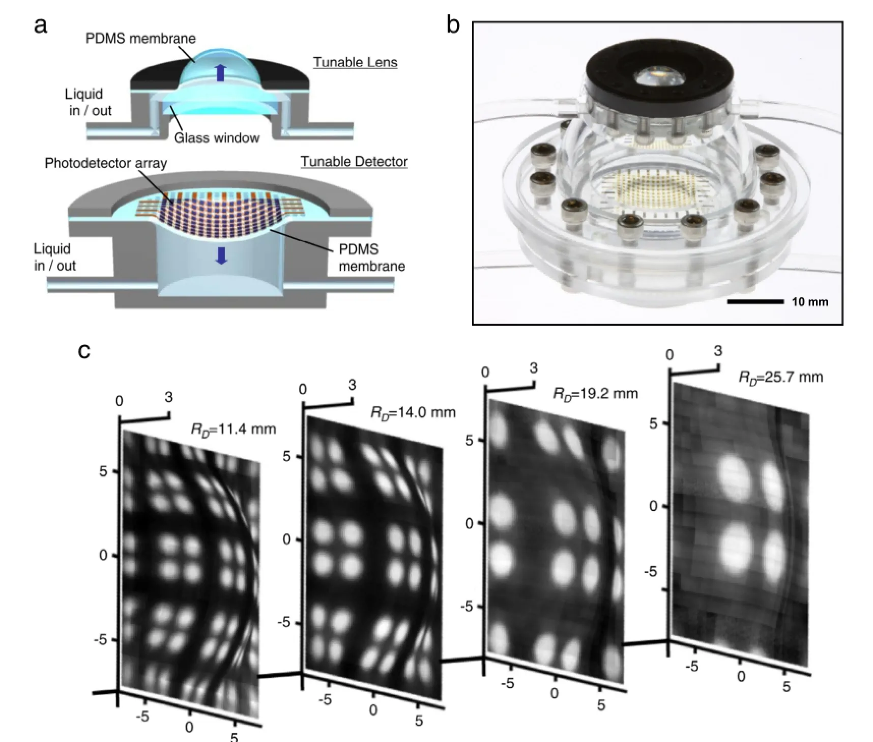
Fig.1.(a)Schematic design of the tunable hemispherical eyeball camera.(b)Optical image of the tunable hemispherical eyeball camera.(c)Images of the same object taken by the camera at different zoom.
tunable lens.Integrating W over the PDMS volume V,the strain energy of the deformed hemispherical lens is obtained as

The virtual work done by the applied pressure is


where G=2C1is the shear modulus.
In practice,fabrication of PDMS membrane and assembling of thesysteminducecompressiveprestrainε0(e.g.−2%)intheinitial state.To account for the effect of prestrain,the initial radius of the PDMS membrane corresponding to the tunable lens prior to prestrainshouldbeRlens/(1+ε0).Thentheprincipalstretchesare
expressed as:

The applied pressure in Eq.(6)becomes

where

Figure 2(b)plots relationships between normalized apex height,and the normalized pressure,,for prestrainε0=0%and−2%.The experiment data are based on Rlens=4.5mmandtlens=0.2mm.Thetheoreticalpredictionwith−2%prestrain shows very good agreement with the experimental results.As shown in Fig.2(b),results from linear elastic model also gives accurate prediction when deformation is small,but deviates from the experiment significantly when deformation is large.
2.2.Mechanics of tunable detector
Figure 2(c)shows the schematic illustration of the tunable detector.The tunable component is a PDMS membrane(thickness tsuband radius Rsub)with integrated silicon photodetectors. By controlling water pressure in the chamber,the detector is deformed to a concave hemispherical shape of apex height H,radius R,and spherical angleϕmax.The radius and spherical angle can be expressed as
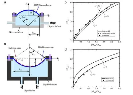
Fig.2.(a)Schematic illustration of the tunable lens.(b)Relationship between normalized apex height H/Rlensand the normalized pressure pRlens/(Gtlens)when prestrain ε0=0%and−2%are considered.(c)Schematic illustration of the tunable detector.(d)Normalized apex height H/Rsubversus the normalized pressure pRsub/(Gtsub)for prestrainsε0=0%and 2%and f=30%.

Let f denotes the fill factor of photodetectors on the PDMS membrane,i.e.areal fraction of photodetectors.The total length of photodetectors and that of PDMS uncovered by photodetectors can be expressed as fRsubandrespectively.When
water pressure p is applied,the total length of PDMS uncovered by photodetectorsincreases to.However, thelengthofPDMSunderneathphotodetectorschangesnegligibly, sincetensilestiffnessofthesiliconphotodetectorsisseveralorders of magnitude larger than that of PDMS.Therefore,the principal stretches of PDMS uncovered by the detectors are obtained as
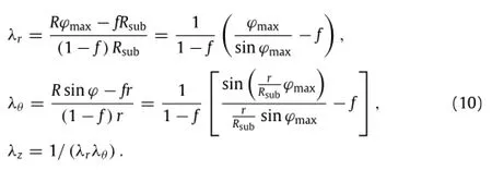
Considering the tensile prestrainε0(e.g.,2%)induced during integrating detectors onto the stage,the principal stretches of PDMS uncovered by photodetectors in the meridional and circumferential directions are given as

Integrating strain energy density over the volume of PDMS uncovered by photodetectors,the total strain energy is obtained a s

where
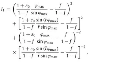
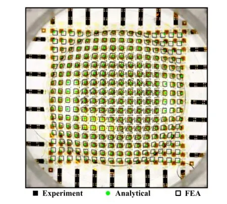
Fig.3.Top view of the photodetector positions given by analytical,experimental and finite element analysis(FEA)studies when apex height H=2.87 mm.
The normalized applied pressure can be obtained by principle of virtual work as

The curves in Fig.2(d)show the relationships between normalized apex height H/Rsub,versus the normalized pressure, pRsub/(Gtsub),for prestrainsε0=0%and 2%.The theoretical prediction is compared with the experimental results for Rsub= 8 mm,tsub=0.4 mm and fill factor f=30%.As shown in the figure,the results show good agreement when 2%prestrain is considered in the theory[42].

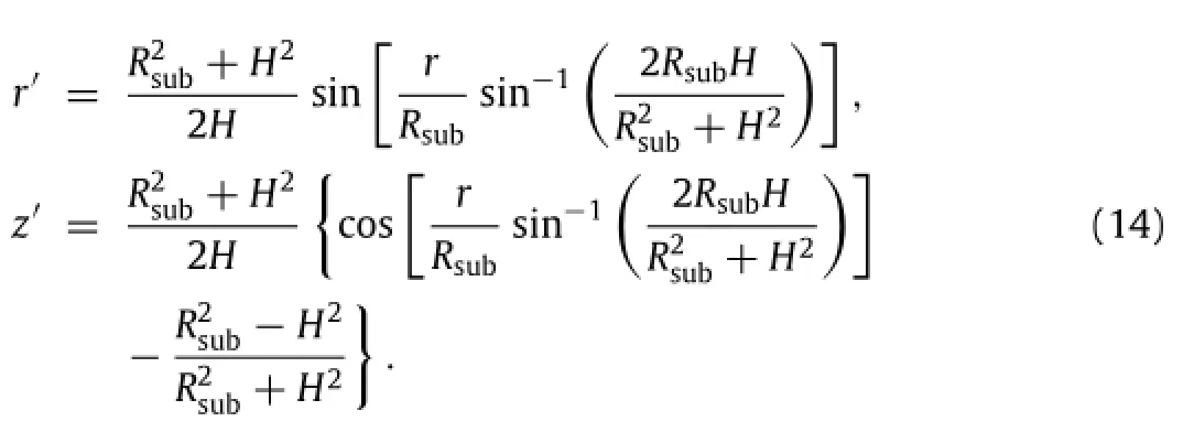
Positions of photodetectors predicted by Eq.(14)are compared with experiment in Fig.3.In experiment,the thickness and radius of PDMS membrane are 0.4 mm and 8 mm,respectively.Figure 3 presents the top view of the photodetector positions when apex height H=2.87 mm[42].Results from analytical,experimental, and FEA studies show good agreement,except for some deviation at the four corners.Deviation at the four corners is probably due to excessive confinement.
3.Mechanics of artificial compound eye camera
Many living organisms in nature(e.g.insects and crustaceans) see the world by means of compound eyes,which possess superior imaging characteristics,such as extremely large field of view angle,acutesensingtomotion,andinfinitedepthoffield[7–9].Recently,compound eye-inspired imaging systems have attracted a lot of attention due to the huge potential in medical,industrial and military applications[5,44].Song et al.[43]have successfully realized a digital camera resembling the structure and function of appositioncompoundeyescommonlyfoundinarthropod.Figure4(a) schematically illustrates the fabrication processes.The compound eye camera was composed of two sub-systems,the stretchable microlens array(the optical subsystem)and the stretchable photodiode array(the electronic subsystem).The stretchable PDMS (Sylgard 184)microlens array was consisted of densely packed microlenses,each sitting on a supporting post and joined by a continuous elastomeric base membrane.The stretchable photodiode array adopted an open mesh layout to enable superior stretchability while keeping optoelectronic performance of otherwise fragile silicon.Both arrays were firstly fabricated and combined at their planar configurations,and then transformed into a nearly full hemispherical shape via a hydraulic mechanism.The hemisphericalhybridsystemisshowninFig.4(b).Thesurfaceisdenselypopulated by 180 imaging elements(i.e.ommatidia),comparable to the eyes of fire ants and bark beetles.
During the geometrical transformation,very large deformation is introduced into both the microlens and photodiode arrays.FEA results show that the maximum strain in the whole microlens array can reach as large as 50%,as shown in the right frame of Fig.4(c).Under such large deformation,it is critical to ensure no fracture in silicone photodetectors and precise alignment between the photodiodes and microlenses,for the compound eye camera to operate properly.To achieve these goals,the optical and electrical sub-systems are only partially bonded at the positions of the photodetectors to maintain optical alignment,and also to allow free movement and deformation of the serpentine interconnects to minimize the effect on the overall mechanics.In addition,to maximumthestretchabilityinthephotodetectorarray,serpentine shapes are adopted for electrical interconnects to maximize stretchability.This design strategy can help keep the strains in photodetectors well below the fracture strain(e.g.1%for silicon). As shown in the left frame of Fig.4(c),the maximum strain in the siliconphotodetectormaintainsbelow0.3%,evenwhenthesystem is stretched by 50%.
Another challenge is how to design the optical sub-system such that it can be mechanically stretched to very large extent without deteriorating the optical performance.In this work,strain isolation design concept is adopted,with each microlens sitting on a cylindrical supporting pedestal connected to a continuous PDMS base membrane.By using such a design,the deformation induced by stretching the base membrane can be effectively decoupled from the microlenses,and therefore no adverse effects are introduced to the optical properties.As shown in the left frame of Fig.4(c),the peak strain in the microlens is less than 2%even when geometrical transformation induces 50%stretch in the base membrane.
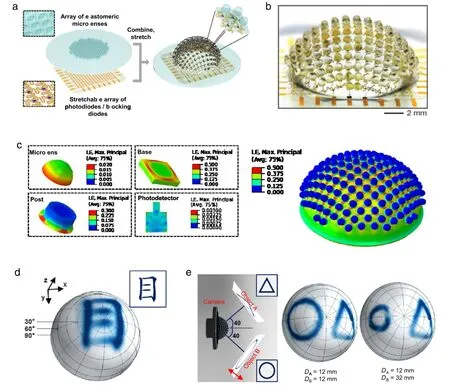
Fig.4.(a)Schematic illustration of the fabrication processes of the artificial compound eye camera.(b)Optical image of the artificial compound eye camera.(c)Strain contours of the entire hemispherical PDMS microlens array(right)and different parts in an ommatidium(left),including microlens,supporting post,base membrane and the photodetector.(d)Picture of a Chinese character‘‘eye’captured by this compound eye camera.(e)Schematic illustration of an experimental setup(left)to demonstrate the infinite depth of field,and pictures of two different objects taken by this camera when they are at the same distances but with different angles(middle)and at different angles and distances(right).
By adopting designs as discussed above,both the microlens and photodetector arrays can be stretched extensively without affecting their optical and electrical performances.Therefore, the hemispherical,apposition compound eye camera can realize superior imaging characteristics.Figure 4(d)exhibits a picture of line art for the Chinese character‘‘eye’captured by this compound eye camera.Figure 4(e)demonstrates one interesting and unique imaging attribute,i.e.,infinite depth of field.The left frame is the schematic illustration of the experimental setup,with two different objects(a triangle and a circle)simultaneously located in front of the camera.At first,these two objects are placed at the same distance to the camera but with different angular positions.Both objects can be clearly captured by the camera simultaneously,which illustrates large field of view angle of this camera.Next,the circle is moved away from the camera while the position of the triangle is fixed.Even now,the camera can still form clear pictures of both objects simultaneously.This simple experiment demonstrates that such a camera has the ability to capturer multiple objects in the field of view even when they are of very different angles and distances.
3.1.Mechanics of geometrical transformation of the compound eye camera
Figure 5(a)–(c)schematically illustrates the geometrical transformation of the elastomeric microlens array from planar to hemispherical shape,by using hydraulic actuation.As shown in Fig.5(a),the array is secured by a stiff ring of radius R1above a water chamber with a circular opening of radius of R2.The inner edge of the ring is rounded,with radius r0.Water pressure inside the chamber deforms the PDMS membrane into a hemispherical cap, as shown in Fig.5(b).During deformation,due to thickness reduction in the PDMS caused by stretching,sliding occurs between the PDMS and the stiff ring in the region highlighted by red in Fig.5(c).
A uniform PDMS membrane is used to approximate the response of the microlens array.When water pressure is applied, the base membrane deforms to be a hemisphere with the peak deflection H.The radius of the hemisphere R and spherical angle ϕmaxare expressed as

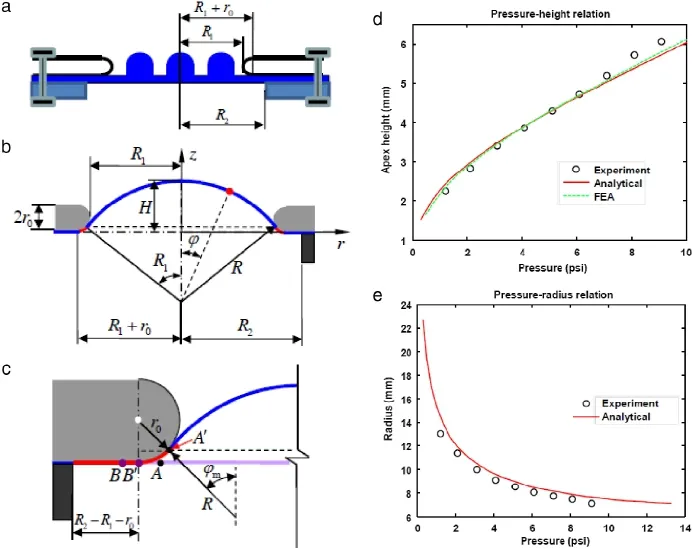
Fig.5.(a)Schematic illustration of the initially flat configuration of the stretchable microlens array.(b)Schematic illustration of the deformed,hemispherical microlens array.(c)Illustration of sliding between the stiff ring and the PDMS membrane.(d)The relationship between the apex height of the microlens array and applied hydraulic pressure obtained by experimental measurement(circle line),analytical model(red line)and FEA(green line).(e)The radius of curvature of the microlens array versus the applied hydraulic pressure,given by analytical(red line)and experimental(black circles)studies.(For interpretation of the references to color in this figure legend,the reader is referred to the web version of this article.)
The separation point A′in the deformed configuration is where the membrane separates from the stiff ring.Its cylindrical coordinate is

The radial coordinate of point A in the initial configuration corresponding to A′is

For any material point initially at(r<rA,θ,0),it moves to a new position on the hemispherical cap with a polar angleThe principle stretches at this point are

The point B′is the connecting point in the deformed configuration between the flat region and the curved region in contact with the stiff ring.The radial coordinate of its corresponding point B in the
initial configuration is

The contact region between the PDMS and the stiff ring consists of two parts,the flat region(rB≤r≤ R2)and the curved region (rA≤r≤rB).The principle stretches in the curved region are

The principle stretches in the flat region are

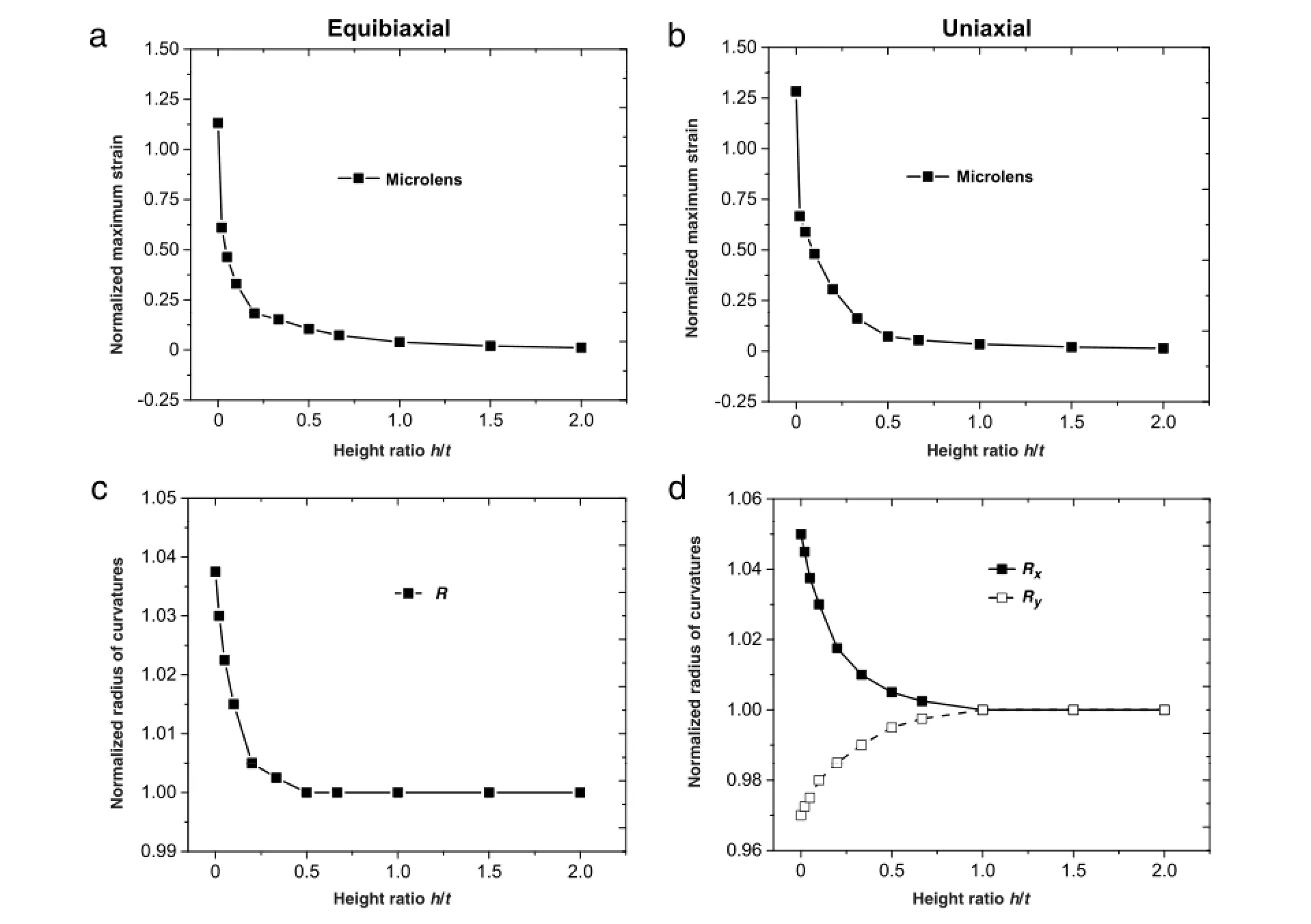
Fig.6.Relationships between the normalized maximum strain and the height ratio h/t for a microlens unit cell subject to(a)equibiaxial tension and(b)uniaxial tension. The normalized radius of curvature of the deformed microlens versus the height ratio h/t when equibiaxial(c)and uniaxial(d)tension are applied.
By adopting Yeoh hyperelastic model,the elastic strain energy in the PDMS membrane is obtained as
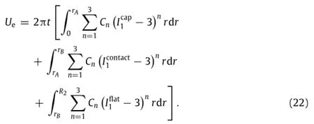
The work done by the hydraulic pressure p is


Figure 5(d)compares the analytical results given by Eq. (24)with the experiment and FEA results,which shows good agreement.Theanalyticalrelationshipbetweenradiusofcurvature R and the applied water pressure also exhibits good agreement with the experimental results,as shown in Fig.5(e).
3.2.Mechanics and optics of stretchable elastomeric microlenses
For the compound eye camera,one key mechanics design is adopting strain-isolation concept in the stretchable microlens array by introducing the supporting post between each microlens andthebasemembrane.Astheheightofsupportingpostincreases, the overall strain level in the microlens is expected to decrease. On the other hand,the photodetector should be placed at the focal point of the microlens to gain best imaging performance.So thesummationofhemisphericalmicrolensradius,supportingpost height and the base membrane thickness should be equal to the focal length of the microlens.Therefore,it is critically important to properly design an elastomeric microlens array that can be mechanically stretched to very large extent without introducing adverse effect to the optical performance.
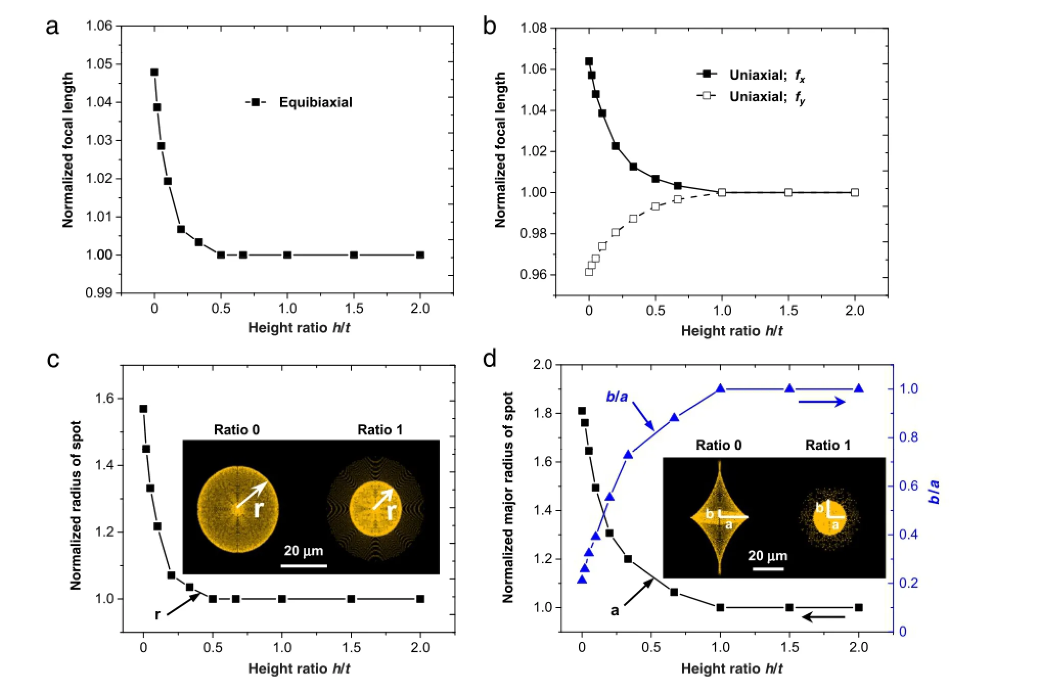
Fig.7.Curves of normalized focal length of the microlens versus the height ratio h/t under(a)equibiaxial and(b)uniaxial tension.Relationships between normalized radius of image spot and the height ratio h/t under(c)equibiaxial and(d)uniaxial tension.The insets are the shapes of the image spots.
Here,the radius of the microlens is fixed,so the summation of the supporting post height h and base membrane thickness t will be kept constant to meet optical requirements.However,their ratio h/t can be engineered to change the mechanics.Due to the periodic nature of the whole structure,one unit cell(i.e.artificial ommatidium)that contains a microlens,supporting post and base membrane is chosen to conduct FEA.During geometrical transformation of the microlens array from flat to hemispherical shape,the strain at the periphery is uniaxial and the strain at the center is equibiaxial.Therefore,both uniaxial and equibiaxial stretchingareconsidered.Figure6(a)and(b)showtherelationship between the maximum strain normalized by the applied strain in the microlens and the height ratio h/t under equibiaxial and uniaxial tension respectively.Under both equibiaxial and uniaxial tension,the normalized maximum strain in the microlens decreases dramatically as the ratio h/t increases.Once the ratio h/t is larger than 1,the maximum strain in the microlens is negligibly small.It was also shown that the surface profile of the deformed microlens can be very well fitted by a hemispherical cap.The relationships between the radius of the hemispherical cap and the height ratio,under equibiaxial and uniaxial tension are presented in Fig.6(c)and(d),respectively.Under equibiaxial tension,the radius of the microlens increases,but the shape keeps hemispherical.However,when uniaxial tension is applied, the shape of the microlens changes to be oblate,which can be characterized by major and minor axes,Rxand Ry.It is also clearly demonstrated by Fig.6(c)and(d)that once the height ratio h/t is greater than 1,the change in the surface profile of the microlens is negligible.
Based on the results from mechanics simulations,optical raytracing simulation is used to study the change in optical properties (e.g.focal length and image spot)of the microlens unit cell subject to stretching.Figure 7(a)and(b)show the curves of focal length of the microlens normalized by that of undeformed microlens versus the height ratio h/t under equibiaxial and uniaxial tension, respectively.Under equibiaxial tension,the focal length is larger than that of the undeformed microlens,but it decreases rapidly as the height ratio increases.Once the height ratio is larger than 1, the focal length is equal to that of undeformed microlens.Similar trend can be seen when uniaxial tension is applied,as shown in Fig.7(b).The influence on imaging characteristics of the microlens is presented in Fig.7(c)and(d),when the microlens is subject equibiaxial and uniaxial tension,respectively.The geometry of image spot of the light beam focused by the microlens is important for the design of photodetectors.The inset in Fig.7(c)shows the shapes of two image spots focused by the microlens with and without supporting post under equibiaxial tension.The difference in size is significant.The spot radius normalized by that of the undeformed microlens versus the height ratio is exhibited in Fig.7(c).The spot size quickly decreases as the height ratio h/t increases,and it reaches the spot size of the undeformed lens once h/t is greater than 1.Figure 7(d)presents normalized major radius of spot and the ratio of minor radius over major radius(b/a) versus the height ratio h/t.The spot size quickly approaches that of undeformed microlens as h/t increases.Once h/t is greater than 1,the effect of stretching on imaging is negligible.
4.Conclusion and discussion
This article has reviewed the progress in mechanics of bioinspired imaging systems,including the dynamically tunable hemispherical eyeball camera and the artificial compound eye camera.Mechanics analysis illustrates the relationships between the deformation of the tunable lens and tunable detector and the hydraulic pressure,which can be used for not only designing the tunable electronic eyeball camera,but also guiding the system operation.A simple mechanics model is also established to track the positions of photodetectors on the dynamically deforming hemispherical surface,which is critically important for image post-processing.For the artificial compound eye camera,the relationship between the deformation of the hybrid system and the actuation pressure is also given by an analytical mechanics model.Computational mechanics and optics study on stretchable microlens provides important guidance for designing elastomericmicrolens arrays that can sustain very large strain without sacrificing the optical performance.The results and models reviewed in this article can provide important guidance for the design of similar systems,and can also find applications in other systems that require dynamical tunability,stretchable optoelectronics and optics.
It is also notable to mention that in the systems reviewed here, the geometrical transformation requires external actuation,such as hydraulic mechanisms.Recent research in soft active materials might potentially broaden the application range of stretchable optoelectronics[51–57],since they can deform by themselves in response to environmental stimuli.For example,SMPs can recover as large as 400%programmed strain in response to different environmental stimuli,such as heat,humidity and magnetic field [51,54].The effect of strain on optics was eliminated in the design of stretchable elastomeric microlens array as reviewed in this article,however,it could be useful in other applications.For example,recent studies have shown that tunable optics can have many interesting applications,and the mechanisms can be used to tune optics include strain[32,33],electrowetting[38],hydraulics [34,35,42],dielectric[39]and electromagnetic actuation[40].
Acknowledgments
TheauthorsgratefullyacknowledgesupportfromACSPetroleum Research Fund(Grant No.53780-DNI7)and NSF(Grant No.CMMI-1405355).
References
[1]M.F.Land,D.E.Nillson,Animal Eyes,Oxford Univ.Press,2012.
[2]M.F.Land,The optics of animal eyes,Contemp.Phys.29(1988)435–455.
[3]D.E.Nilsson,A new type of imaging optics in compound eyes,Nature 332 (1988)76–78.
[4]J.Zeil,A new kind of neural superposition eye:the compound eye of male Bibionidae,Nature 278(1979)249–250.
[5]L.P.Lee,R.Szema,Inspirations from biological optics for advanced photonic systems,Science 310(2005)1148–1150.
[6]A.Borst,J.Plett,Optical devices:Seeing the world through an insect’s eyes, Nature 497(2013)47–48.
[7]E.Warrant,D.E.Nillson,Invertebrate Vision,Cambridge Univ.Press,2006.
[8]R.Dudley,The Biomechanics of Insect Flight:Form,Function,Evolution, Princeton Univ.Press,2000.
[9]D.Floreano,J.C.Zufferey,M.V.Srinivasan,et al.,Flying Insects and Robot, Springer,New York,2009.
[10]K.H.Jeong,J.Kim,L.P.Lee,Biologically inspired artificial compound eyes, Science 312(2006)557–561.
[11]T.Someya,Optics:Electronic eyeballs,Nature 454(2008)703–704.
[12]R.G.Arns,Theothertransistor:earlyhistoryofthemetal-oxidesemiconductor field-effect transistor,Eng.Sci.Educ.J.7(1998)233–240.
[13]G.E.Moore,Cramming more components onto integrated circuits,Proc.IEEE 86(1998)82–85.
[14]I.Hayashi,Optoelectronic devices and material technologies for photoelectronic integrated systems,Japan.J.Appl.Phys.32(1993)266.
[15]Z.Li,Y.Wang,J.Xiao,Mechanicsofcurvilinearelectronicsandoptoelectronics, Curr.Opin.Solid State Mater.Sci.19(2015)171–189.
[16]H.C.Ko,G.Shin,S.Wang,et al.,Curvilinear electronics formed using silicon membrane circuits and elastomeric transfer elements,Small 5(2009) 2703–2709.
[17]S.Wang,J.Xiao,J.Song,et al.,Mechanics of curvilinear electronics,Soft Matter 6(2010)5757–5763.
[18]J.A.Rogers,T.Someya,Y.Huang,Materials and mechanics for stretchable electronics,Science 327(2010)1603–1607.
[19]D.H.Kim,J.Xiao,J.Song,et al.,Stretchable,curvilinear electronics based on inorganic materials,Adv.Mater.22(2010)2108–2124.
[20]J.A.Rogers,Materials for semiconductor devices that can bend,fold,twist,and stretch,MRS Bull.39(2014)549–556.
[21]D.H.Kim,N.Lu,Y.Huang,et al.,Materials for stretchable electronics in bioinspired and biointegrated devices,MRS Bull.37(2012)226–235.
[22]Y.Zhang,Y.Huang,J.A.Rogers,Mechanics of stretchable batteries and supercapacitors,Curr.Opin.Solid State Mater.Sci.19(2015)190–199.
[23]N.Lu,S.Yang,Mechanics for stretchable sensors,Curr.Opin.Solid State Mater. Sci.19(2015)149–159.
[24]D.Kang,S.M.Lee,Z.Li,et al.,Compliant,heterogeneously integrated GaAs Micro-VCSELs towards wearable and implantable integrated optoelectronics platforms,Adv.Opt.Mater.2(2014)373–381.
[25]H.C.Ko,M.P.Stoykovich,J.Song,et al.,A hemispherical electronic eye camera based on compressible silicon optoelectronics,Nature 454(2008)748–753.
[26]G.Shin,I.Jung,V.Malyarchuk,etal.,Micromechanicsandadvanceddesignsfor curved photodetector arrays in hemispherical electronic-eye cameras,Small 6 (2010)851–856.
[27]I.Jung,G.Shin,V.Malyarchuk,et al.,Paraboloid electronic eye cameras using deformable arrays of photodetectors in hexagonal mesh layouts,Appl.Phys. Lett.96(2010)021110.
[28]C.C.Huang,X.Wu,H.Liu,et al.,Large-field-of-view wide-spectrum artificial reflecting superposition compound eyes,Small 10(2014)3050–3057.
[29]L.Li,A.Y.Yi,Development of a 3D artificial compound eye,Opt.Express 18 (2010)18125–18137.
[30]X.Xu,M.Davanco,X.Qi,et al.,Direct transfer patterning on three dimensionally deformed surfaces at micrometer resolutions and its application to hemispherical focal plane detector arrays,Organ.Electron.9(2008)1122–1127.
[31]S.Wang,J.Xiao,I.Jung,et al.,Mechanics of hemispherical electronics,Appl. Phys.Lett.95(2009)181912.
[32]Z.Li,J.Xiao,Strain tunable optics of elastomeric microlens array,Extreme Mech.Lett.4(2015)118–123.
[33]D.Chandra,S.Yang,P.C.Lin,Strain responsive concave and convex microlens arrays,Appl.Phys.Lett.91(2007)251912.
[34]S.T.Choi,J.Y.Lee,J.O.Kwon,et al.,Varifocal liquid-filled microlens operated by an electroactive polymer actuator,Opt.Lett.36(2011)1920–1922.
[35]S.T.Choi,B.S.Son,G.W.Seo,et al.,Opto-mechanical analysis of nonlinear elastomermembranedeformationunderhydraulicpressureforvariable-focus liquid-filled microlenses,Opt.Express 22(2014)6133–6146.
[36]L.Dong,A.K.Agarwal,D.J.Beebe,et al.,Adaptive liquid microlenses activated by stimuli-responsive hydrogels,Nature 442(2006)551–554.
[37]L.Dong,A.K.Agarwal,D.J.Beebe,et al.,Variable-focus liquid microlenses and microlens arrays actuated by thermoresponsive hydrogels,Adv.Mater.19 (2007)401–405.
[38]T.Krupenkin,S.Yang,P.Mach,Tunable liquid microlens,Appl.Phys.Lett.82 (2003)316–318.
[39]F.Carpi,G.Frediani,S.Turco,et al.,Bioinspired tunable lens with muscle-like electroactive elastomers,Adv.Funct.Mater.21(2011)4152–4158.
[40]P.Liebetraut,S.Petsch,W.Mönch,et al.,Tunable solid-body elastomer lenses with electromagnetic actuation,Appl.Opt.50(2011)3268–3274.
[41]A.Llobera,R.Wilke,S.Büttgenbach,Poly(dimethylsiloxane)hollow Abbe prismwithmicrolensesfordetectionbasedonabsorptionandrefractiveindex shift,Lab Chip 4(2004)24–27.
[42]I.Jung,J.Xiao,V.Malyarchuk,et al.,Dynamically tunable hemispherical electronic eye camera system with adjustable zoom capability,Proc.Natl. Acad.Sci.108(2011)1788–1793.
[43]Y.M.Song,Y.Xie,V.Malyarchuk,et al.,Digital cameras with designs inspired by the arthropod eye,Nature 497(2013)95–99.
[44]Z.Li,J.Xiao,Mechanics and optics of stretchable elastomeric microlens array for artificial compound eye camera,J.Appl.Phys.117(2015)014904.
[45]D.Floreano,R.Pericet-Camara,S.Viollet,et al.,Miniature curved artificial compound eyes,Proc.Natl.Acad.Sci.110(2013)9267–9272.
[46]H.Zhang,L.Li,D.L.McCray,et al.,Development of a low cost high precision three-layer 3D artificial compound eye,Opt.Express 21(2013)22232–22245.
[47]A.Brückner,J.Duparré,R.Leitel,et al.,Thin wafer-level camera lenses inspired by insect compound eyes,Opt.Express 18(2010)24379–24394.
[48]K.Stollberg,A.Brückner,J.Duparré,et al.,The Gabor superlens as an alternativewafer-levelcameraapproachinspiredbysuperpositioncompound eyes of nocturnal insects,Opt.Express 17(2009)15747–15759.
[49]O.H.Yeoh,Some forms of the strain energy function for rubber,Rubber Chem. Technol.66(1993)754–771.
[50]C.Lü,M.Li,J.Xiao,et al.,Mechanics of tunable hemispherical electronic eye camera systems that combine rigid device elements with soft elastomers, J.Appl.Mech.80(2013)061022.
[51]H.Meng,G.Li,A review of stimuli-responsive shape memory polymer composites,Polymer 54(2013)2199–2221.
[52]T.Xie,Tunable polymer multi-shape memory effect,Nature 464(2010) 267–270.
[53]L.M.Cox,J.P.Killgore,Z.Li,etal.,Morphingmetal–polymerJanusparticles,Adv. Mater.26(2014)899–904.
[54]Q.Zhao,H.J.Qi,T.Xie,Recent progress in shape memory polymer:New behavior,enablingmaterials,andmechanisticunderstanding,Prog.Polym.Sci. 49–50(2015)79–120.
[55]L.M.Cox,Z.Li,N.Sowan,et al.,Reconfigurable surface patterns on covalent adaptive network polymers using nanoimprint lithography,Polymer 55 (2014)5933–5937.
[56]S.H.Maruf,Z.Li,J.A.Yoshimura,et al.,Influence of nanoimprint lithography on membrane structure and performance,Polymer 69(2015)129–137.
[57]C.Yu,Z.Duan,P.Yuan,et al.,Electronically programmable,reversible shape change in two-and three-dimensional hydrogel structures,Adv.Mater.25 (2013)1541–1546.
7 October 2015
http://dx.doi.org/10.1016/j.taml.2015.11.011
2095-0349/©2015 The Authors.Published by Elsevier Ltd on behalf of The Chinese Society of Theoretical and Applied Mechanics.This is an open access article under the CC BY-NC-ND license(http://creativecommons.org/licenses/by-nc-nd/4.0/).
∗.
E-mail address:jianliang.xiao@colorado.edu(J.Xiao).
杂志排行
Theoretical & Applied Mechanics Letters的其它文章
- Editorial:Recent advances in mechanics of unconventional electronics
- The finite deformation of the balloon catheter
- Adhesion-governed buckling of thin-film electronics on soft tissues
- Recent development of transient electronics
- Recent advances on thermal analysis of stretchable electronics
- Acoustomechanics of semicrystalline polymers
