Producing ultra-high-speed nitrogen jets by arc heating in a low-pressure chamber
2016-12-09WenxiaPanXianMengHejiHuangChengkangWu
Wenxia Pan,Xian Meng,Heji Huang,Chengkang Wu
The State Key Laboratory of High Temperature Gas Dynamics,Institute of Mechanics,Chinese Academy of Sciences,Beijing 100190,China
Letter
Producing ultra-high-speed nitrogen jets by arc heating in a low-pressure chamber
Wenxia Pan∗,Xian Meng,Heji Huang,Chengkang Wu
The State Key Laboratory of High Temperature Gas Dynamics,Institute of Mechanics,Chinese Academy of Sciences,Beijing 100190,China
H I G H L I G H T S
•Pure nitrogen was accelerated with a low-power arc-heater of novel structure.
•The jet flow can reach very high speed around 7 km/s.
•A bypass-exhaust for cool boundary layer at end of the throat plays an important role.
A R T I C L EI N F O
Article history:
Accepted 18 December 2015
Available online 16 January 2016
Low-power nitrogen arc-heater
Lateral bypass-exhausting
Very high flow speed
Nozzle structure
Chamber pressure
Pure nitrogen gas was heated with direct current arc,at input powers from several hundred W to over 5 kW,and then injected through a nozzle into a chamber at 1 or 10 Pa pressure,with the purpose of accelerating the gas to very high speed around 7 km/s.Various structures of the arc generator and gas expansion nozzle were examined.Results show that bypass exhausting of the boundary layer before it enters the nozzle divergent section can greatly increase flow speed of the jet,thus it might be possible to use nitrogen as a working gas in high speed gas dynamic test facilities.
©2016 The Authors.Published by Elsevier Ltd on behalf of The Chinese Society of Theoretical and Applied Mechanics.This is an open access article under the CC BY-NC-ND license(http:// creativecommons.org/licenses/by-nc-nd/4.0/).
Non-transferred direct current(dc)arc heaters,extremely high temperature gas heaters or plasma jet generators are widely used in materials processing[1,2],space thruster application[3,4]and wind-tunnel test facilities[5,6]for high speed flight.One feature of these installations might be the production of high speed, high total-temperature jet,which may have various significance in different applications.Nitrogen is a popular working gas for arc heating application in industry usages.However,it is quite difficulttobeacceleratedtoveryhighflowvelocitiesbyarcheating and nozzle expansion,to be used for space thruster and special high speed flow testing applications.Thus,few research results have been reported for nitrogen propellant arcjet thrusters[7], compared with hydrogen,ammonia and helium propellants,etc. Generally,specific impulse of nitrogen arcjet is much lower than 300 s[7],and its maximum axial flow velocity near the nozzle exit center is around 4 km/s[8].
Flow in the small nozzles used in low-power arcjets demonstrates much more complicated phenomena and energy conversion mechanism than those in the normal rocket,although their working principles are basically similar.Arcjets are also quite differentinworkingprincipleasotherelectricthrustersliketheionor Hall engine.In testing of the arcjets in low-pressure environments, the propellant flow rates are much higher compared to other kinds of electric thrusters.This causes difficulty in keeping a high vacuum level in the simulation facility chamber and in reflecting the real performance which an arcjet would have in space propulsion. Atthesametime,itisdifficulttolimitthegasfeedingsimplybyreducing the diameter of throat because of the relative thick boundary layer in the small flow passage[9].
It is the purpose of this work to study ways of producing very high speed nitrogen jets,to see if they might be useful in certain special applications.In these experiments,pure nitrogen,heated by an electric arc,was expanded through a small nozzle and issued into a low-pressure chamber as a high speed jet.The construction of the heater-nozzle combination and the operating conditions were varied to see their effects on the jet performance when injected into different environment pressures.An effort was made to relieve the effects of the thick boundary layer:a lateral bypassing exhaust technique was adopted at the throat exit section,with the purpose of producing a high speed nitrogen jet in the exhaust chamber.

Fig.1.The schematic diagram of arc heater(Structure D).
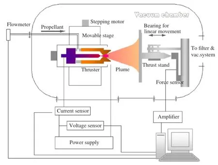
Fig.2.Schematic drawing of the facility.
Four structures of anode/nozzle were studied:A,throat dia. 0.7 mm,expansion half-angle 20°,expansion area ratio 204;B, throat dia.0.6 mm,expansion half-angle 20°,expansion area ratio 220;C,throat dia.0.6 mm,expansion half-angle 15°,expansion area ratio 220;D,throat dia.1.1 mm,expansion half-angle 20°, expansion area ratio 330,with a bypass exhausting structure. Schematic diagram of the arc heater D is shown in Fig.1.Pure nitrogen was used as the working gas.The experiments were run within the range of stable operation of the arc and where long run time could be maintained without burning out or damage of the nozzle.This limits the range of arc current to an order of 10 A for the nozzle A,B and C,and 50 A for nozzle D,corresponding gas flow rates 50 mg/s and 208 mg/s,respectively.In structure D,an annular slit of about 0.4 mm width is opened at the end of the throat section,connected to the Roots and mechanical pumps. This arrangement provides means to pump out the cooler,higherdensity gases near the wall,so that the hotter gas at the center of the electric arc can expand more fully in the divergent portion of the nozzle.The diverted flow rate was measured by a flow meter.
Figure 2 shows the schematic drawing of the facility consisting of a vacuum chamber,2 m diameter by 4 m long,ultimate vacuum 10−4Pa.Two sets of vacuum pumps,one with a Roots blower and a mechanical pump for higher operational flow rates at~10 Pa chamberpressure,anotherwithanadditionaldiffusionpumpwith maximum exhausting rate of 30 000 L/s and molecular pumps of total 7000 L/s exhausting rate for lower flow rates at~1 Pa. The chamber pressure was detected with a capacitance gauge with measuring range of 0.01 Pa–133 Pa.The chamber pressure shows a rapid change during arc ignition or working parameters adjustment,but these fluctuations are much smaller than in the situation when small chamber and high gas flow rate are used,and the present data were taken under conditions where the pressure wassteady.Thearcheaterismountedonamovabletabledrivenby steppingmotors.Theproducedthrustismeasuredindirectlybythe impulse method[10].The mass flow rate,arc current and voltage, pressures,etc.are measured by transducers and were collected on a computer.From the measured parameters,the specific power input,specific impulse and thrust efficiency are calculated[9].The specific impulse actually reflects the average axial speed of the exhausting jet.
For non-transferred dc-arc gas heater of a given structure,the range of operating parameters for stable operation and negligible erosion of the electrodes is not very wide.And to keep a nearly constant environmental pressure in the vacuum chamber with a givensetofpumps,theflowrateofthegasheater isbasicallyfixed. Thus the data presented are rather limited in range.Data for the different nozzle structures and at 10 or 1 Pa exhaust pressures are given in the same diagrams to see the differences more clearly.
Figure 3 shows the voltage–current characteristics of the heaters at 10 Pa and 1 Pa exhaust pressure.The arc voltage always rises with increasing flow rate.Nozzle D has much higher arc voltage,because it uses much higher flow rate and arc current, and cannot be directly compared with the other nozzles.At the same vacuum chamber pressure of 1 Pa and same flow rate and arc current,heater C has significantly higher arc voltage than heater B.This could be caused by different arc anode root attachment positions in the two heaters with their different nozzle configuration.
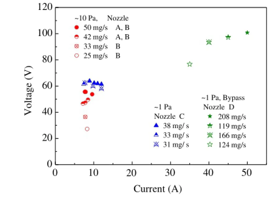
Fig.3.The voltage–current characteristics of the heaters at 10 Pa and 1 Pa exhaust pressure.
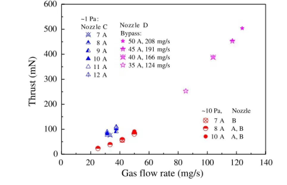
Fig.4.Variations of the thrust with gas flow rate.
The thrust produced by the exhausting jet is related to the gas velocity and the flow rate,the measured results are shown in Fig.4.For nozzle D,the flow rate shown is the value of the total flow subtracted by the laterally exhausted flow,since the latter has no effect whatsoever on the thrust,which was measured by the indirect method of impulse against the flat plate[10].The maximum flow of the laterally exhausted gas is determined by the condition in the arc chamber(total flow rate and arc current) and is not arbitrarily controllable.As shown in Fig.4,at 50 A arc current,total flow 208 mg/s and laterally exhausted flow 84 mg/s, the nozzle exhaust flow producing the thrust is 124 mg/s.
For nozzles A and B,at the same exhaust chamber pressure of 10 Pa,the thrust vs.flow rate characteristics are the same,but at exhaust chamber pressure of 1 Pa,the thrust is higher than that at 10 Pa,with same arc current and gas flow rate.This phenomenon is not compatible with the ordinary concept of supersonic nozzle flow that pressure beyond the supersonic nozzle exit would not affect the flow inside the nozzle.The explanation may lie in the existence of very thick boundary layer in nozzles with throat diameterunder1mm,sothatlargesectionsoftheflowthroughout the nozzle are subsonic,as has been studied in Argon and Helium nozzle flows in Ref.[9].
The specific impulse is deduced from the ratio of measured thrust and the flow rate producing the thrust,shown in Fig.5. Clearly,the specific impulse produced by the jet at exhaust pressure of 1 Pa is much higher than that at 10 Pa,at same arc current and gas flow rate.The reason for this is that the lower back pressure allows for fuller expansion in these low Reynolds number flows where very thick boundary layers prevent an ideal gas flow expansion.For nozzle D,at 5 kW input power,the specific impulse with the laterally exhausted gas flow rate deducted from the total is greater than 400 s.The estimated average exhaust gas velocity is over 4 km/s.With exit velocity usually in a parabolic distribution for such nozzles[8],the velocity in central part of the jet can easily exceed 6 km/s.This velocity is not ordinarily achievable in nitrogen jets of small size produced in arc-heated nozzles.In later work,this nozzle has been tested in a small-scale rarefied gas wind tunnel.Under similar operating conditions as in this work,the flow velocity in the central portion of the jet measured by laser-induced-fluorescence coupled with high-speed ICCD camera method was above 7 km/s.Such velocities would be useful in studying interaction between rarefied hypersonic flow and body surfaces.
The abscissa in Fig.5(b)is specific power,i.e.the ratio of input electric power to the input mass flow rate.Here,for nozzle D operating at relatively high power,part of the hot gas is exhausted near the end of the throat section.The green data points are for total flow rates,and the purplish red points are for the net flow producing thrust.The laterally exhausted flow rates are 84,74,62, and 39 mg/s at total flow rates of 208,191,166 and 124 mg/s. The ratios of exhausted to total flow are 40%,39%,37%and 32%, respectively.Considering nozzle temperature not over 2000 K in general,it can be assumed that the average temperature T of the gas boundary layer exhausted to be 4000 K.The enthalpy h of nitrogen gas can be expressed as

in the temperature range of 350–4000 K.Thus the rate of energy flowing out with the laterally exhausted gas is 394 W,347 W, 293 W,and 185 W taking 7.8%,7.9%,7.8%,and 6.9%from the total power input,respectively.
From these data,it can be seen that a certain high rate of flow is necessary to be compatible with the relatively high power input conditions,and the lower-temperature,higher-density gas near the wall is beneficial for the protection of the components from the high-temperature arc.After performing this useful function,it is exhausted laterally,bringing with it a not-too-high proportion of the input energy.If this part of the gas is not exhausted but participates in the expansion through the nozzle,it will definitely reduce the specific impulse(or jet velocity).There are no directlycompareddataforconstructionDwithandwithoutbypass exhausting,because if this gas is not pumped out beforehand,the chamber pressure would be well above 10 Pa.The 30 000 L/s diffusion pump used in this facility has a limiting point at about 1 Pa,above which the pumping capacity is reduced dramatically.
AsshowninFig.6,thethrustefficiencyofthissetupisquitelow, even though the energy loss connected with the lateral exhausting islessthan10%oftheinput,andtheheatlossisgenerallyestimated to be under 15%.This further loss of efficiency is caused by the incomplete conversion of internal energy of the high-temperature gas entering the divergent section of the nozzle into axial kinetic energy of the gas at the nozzle exit,through the expansion process in the nozzle passage.Taking the 50 A data in Fig.6 as an example, deducting 7.8%energy carried out by the bypassed gas from the electric energy input,the gas at the beginning of expansion in the divergent part of the nozzle would have a specific enthalpy of 3.75× 10⁷J/kg.At a pressure of about 0.2 atm measured at the throat exit section,the average temperature would be 6920 K, calculatedwiththemethodinRef.[11].Furthersubtractingthe15% heat loss and taking the thrust efficiency of 20%as given in Fig.6, the specific enthalpy at the nozzle exit would be 2.33×10⁷J/kg. Neglecting the effect of chemical non-equilibrium in the gases, this would correspond to an average temperature of 4600 K at a pressure of 10 Pa[8,11].This number approximately agrees with the numerical modeling result given in Ref.[8]for a low-power nitrogen arcjet,at an arc current of 10 A and exit pressure of about 100 Pa.The calculated temperature at the center of the jet was above 4000 K,much higher than those in hydrogen arcjets.The insufficient expansion in the divergent part of the nozzle due to the viscosity effects in the low Reynolds number flow could make the conversion process into kinetic energy very inefficient,leaving a large portion of energy in the thermal form(high temperature).Also,nitrogen is a molecular gas of much higher molecular mass than hydrogen,and the chemical non-equilibrium condition in the flow of dissociated nitrogen would leave energy in the frozen dissociation state and detract from the thrust efficiency.These are the reasons for which nitrogen is difficult to be accelerated to very high speed through the arc-heating and expansion process.
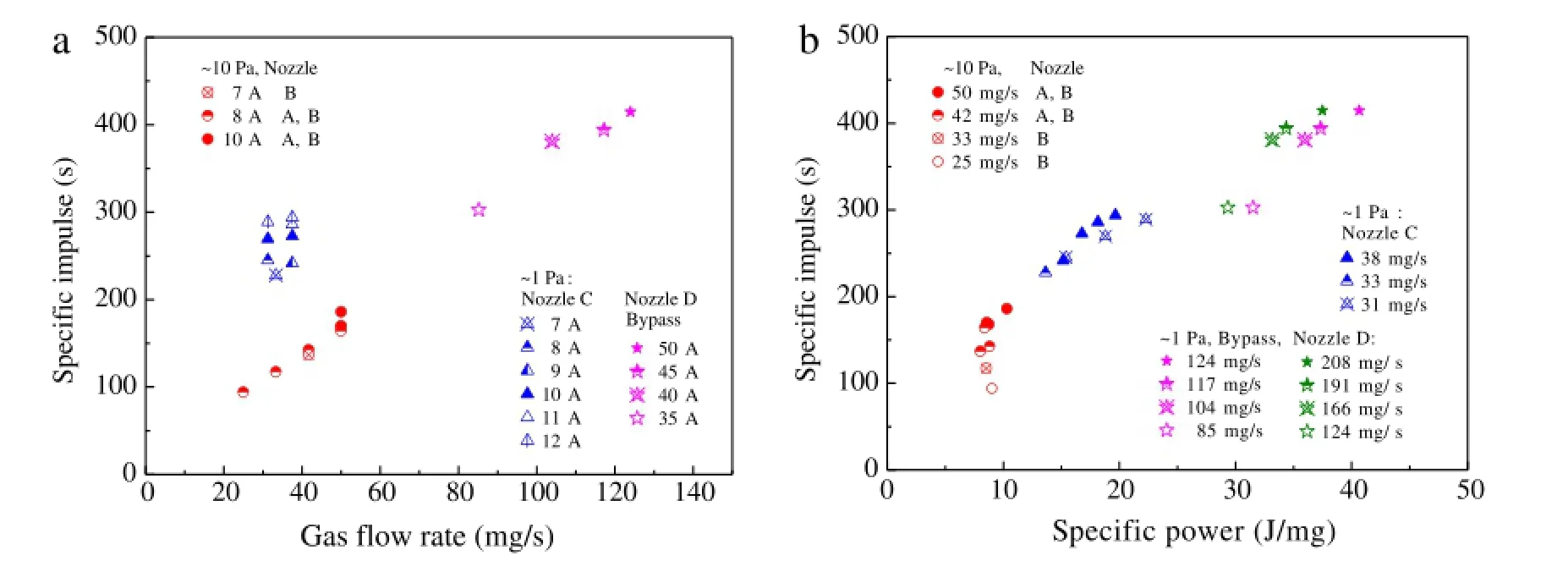
Fig.5.Variations of the specific impulse with gas flow rate(a)and specific power(b).
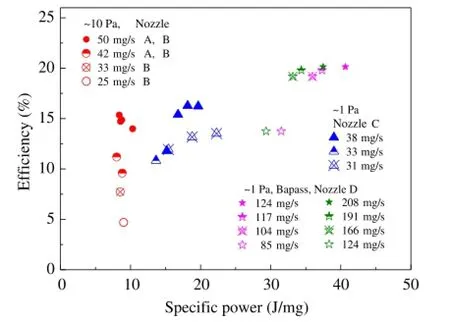
Fig.6.Variations of the thrust efficiency with specific power.
Pure nitrogen is difficult to be accelerated to very high speed through the arc-heating and expansion process.Several structures of low-power arc-heated nitrogen heater with expansion nozzles were tested in a low-pressure chamber.A novel construction which has a lateral bypass-exhausting passage at the end of the throat passage,allowing sucking-off of the relatively cool and higher density boundary layer,enables the central core of the high-temperature flow to expand to a velocity about 7 km/s.This method could be useful in hypersonic rarefied gas wind tunnels using nitrogen as the working media.
Acknowledgment
This work is supported by the National Natural Science Foundation of China(Nos.11575273 and 11475239).
References
[1]J.Mostaghimi,M.I.Boulos,Thermalplasmasources:howwellaretheyadopted to process needs?Plasma Chem.Plasma Process.35(2015)421–436.
[2]E.Pfender,Thermal plasma technology:where do we stand and where are we going?Plasma Chem.Plasma Process.19(1999)1–31.
[3]L.K.Johnson,G.G.Spanjers,D.R.Bromaghim,et al.,On-orbit optical observations of electric propulsion space experiment 26-kilowatt arcjet,J.Propulsion and Power 18(2002)763–767.
[4]Fred.C.Wilson,Recentadvancedinsatellitepropulsionandassociatedmission benefits,AIAA-2006-5307.
[5]O.Chazot,F.Panerai,High-enthalpy facilities and plasma wind tunnels for aerothermodynamics ground testing,in:Hypersonic Nonequilibrium Flows: Fundamentals and Recent Advances,Am.Inst.Aero.&Astro.,Inc.,2015, pp.471–522.
[6]T.M.Dubreus,Development of a mid-pressyre arc-heated facility for hypersonic vihicle testing,AIAA 2010-1732.
[7]H.B.Tang,X.A.Zhang,Y.Liu,et al.,Experimental study of startup characteristics and performance of a low-power arcjet,J.Propulsion and Power 27(2011)218–226.
[8]H.X.Wang,J.Y.Geng,X.Chen,et al.,Modeling study on the flow,heat transfer and energy conversion characteristics of low-power arc-heated hydrogen/nitrogen thrusters,Plasma Chem.Plasma Process.30(2010) 707–731.
[9]C.K.Wu,W.X.Pan,X.Meng,et al.,Mechanisms for non-ideal flow in low-power arc-heated supersonic nozzles,Acta Mech.Sin.31(2015) 500–511.
[10]C.K.Wu,H.X.Wang,X.Meng,Aerodynamics of indirect thrust measurement by the impulse method,Acta.Mech.Sin.27(2011)152–163.
[11]A.B.Murphy,C.J.Arundell,Transport coefficients of argon,nitrogen,oxygen, argon-nitrogen,and argon-oxygen plasmas,Plasma Chem.Plasma Process.14 (1994)451–490.
26 November 2015
http://dx.doi.org/10.1016/j.taml.2015.12.003
2095-0349/©2016 The Authors.Published by Elsevier Ltd on behalf of The Chinese Society of Theoretical and Applied Mechanics.This is an open access article under the CC BY-NC-ND license(http://creativecommons.org/licenses/by-nc-nd/4.0/).
∗.
E-mail address:wxpan@imech.ac.cn(W.Pan).
*This article belongs to the Fluid Mechanics.
杂志排行
Theoretical & Applied Mechanics Letters的其它文章
- Editorial:Recent advances in mechanics of unconventional electronics
- The finite deformation of the balloon catheter
- Adhesion-governed buckling of thin-film electronics on soft tissues
- Mechanics of bioinspired imaging systems
- Recent development of transient electronics
- Recent advances on thermal analysis of stretchable electronics
