Design of multi-layered porous fibrous metals for optimal sound absorption in the low frequency range
2016-12-09WenjiongChenShutinLiuLiyongTongShengLi
Wenjiong Chen,Shutin Liu,∗,Liyong Tong,Sheng Li
aState Key Laboratory of Structural Analysis for Industrial Equipment,Dalian University of Technology,Dalian 116023,China
bSchool of Aerospace,Mechanical and Mechatronic Engineering,The University of Sydney,NSW 2006,Australia
Letter
Design of multi-layered porous fibrous metals for optimal sound absorption in the low frequency range
Wenjiong Chena,Shutian Liua,∗,Liyong Tongb,Sheng Lia
aState Key Laboratory of Structural Analysis for Industrial Equipment,Dalian University of Technology,Dalian 116023,China
bSchool of Aerospace,Mechanical and Mechatronic Engineering,The University of Sydney,NSW 2006,Australia
H I G H L I G H T S
•A method for enhancing sound absorption coefficient of fibrous metals is presented.
•A fibrous layout with given porosity of multi-layered fibrous metals is suggested.
•Appropriate surface porosity balances dissipation and reflection of acoustic energy.
A R T I C L EI N F O
Article history:
Accepted 25 December 2015
Available online 21 January 2016
Porous fibrous metal
Multi-layer
Low frequency
Acoustic model
Design optimization
We present a design method for calculating and optimizing sound absorption coefficient of multi-layered porous fibrous metals(PFM)in the low frequency range.PFM is simplified as an equivalent idealized sheet with all metallic fibers aligned in one direction and distributed in periodic hexagonal patterns.We use a phenomenological model in the literature to investigate the effects of pore geometrical parameters (fiber diameter and gap)on sound absorption performance.The sound absorption coefficient of multilayered PFMs is calculated using impedance translation theorem.To demonstrate the validity of the present model,we compare the predicted results with the experimental data.With the average sound absorption(low frequency range)as the objective function and the fiber gaps as the design variables, an optimization method for multi-layered fibrous metals is proposed.A new fibrous layout with given porosity of multi-layered fibrous metals is suggested to achieve optimal low frequency sound absorption. The sound absorption coefficient of the optimal multi-layered fibrous metal is higher than the singlelayered fibrous metal,and a significant effect of the fibrous material on sound absorption is found due to the surface porosity of the multi-layered fibrous.
©2016 The Authors.Published by Elsevier Ltd on behalf of The Chinese Society of Theoretical and Applied Mechanics.This is an open access article under the CC BY-NC-ND license(http:// creativecommons.org/licenses/by-nc-nd/4.0/).
As a new type of sound-absorbing materials,porous fibrous metal(PFM),e.g.stainless steel and FeCrAl,has been found to be effective in reducing noise.Compared with the conventional nonmetallic porous fibrous material,PFM becomes attractive due to its mechanical properties,e.g.large surface area,low density, excellent permeability and higher mechanical strength.Hence under extreme circumstances(such as acoustical liner of turbofan engine inlet)PFM may be suitable for applications[1,2].Therefore recently the study of the sound absorption performance of PFM is of considerable interest.
PFM often has high porosity,as metal fibers cross over each other and there exist a lot of small air passages in the material.Due to these specific pore geometries,energy dissipation in the forms of damping and thermal loss leads to superior sound absorption performance of the PFM.Similar to most sound porous materials, uniform(homogeneous)PFM has excellent sound absorption properties in middle–high frequency range,however,in the low frequency range,the capability of sound absorption is relatively poor.The most common way to improve the performance in low frequencies is to increase the thickness of material[3].However, this approach may limit the development of PFM to control noise in microelectronics and precision instruments.An alternative way is to optimize the pore geometric parameters to influence the sound propagation in the fibrous material.It has also been found that the gradient porosity can improve PFM’s sound absorption performance[1,3–5].An analysis and design model is in need to be established for designing optimal pore geometric parameter distribution.
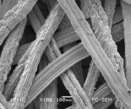
Fig.1.A typical structural configuration of PFM[12].
Many researchers have studied the acoustic model for predicting the sound absorption properties of uniform porous materials. These models generally fall into two types:empirical and phenomenological models.Bazley and Delany[6]have proposed one of the most representative empirical model.This model can be used to study the single parameter’s influence on sound absorption properties,such as state air-flow resistivity,and may not be directly used for studying microscopic structure of porous material.Apart from the empirical model,a number of phenomenological models have also been established,for example,the Biot model[7],Johnson–Champoux–Allard(JCA)model[8,9],Wilson model[10]Lafarge model[11],etc.Accuracy is improved by these models through introducing extra macroscopic acoustic parameters,which are usually obtained through solving the viscous boundaryvalueproblemsoftheporestructure.Relationshipofmaterial’s sound absorption properties and the pore structure can be established using the JCA model,since it is accurate in both high and low frequencies.Therefore,the JCA model is employed to determine the sound absorption characteristics of PFM in this study. In this paper,an optimization method of designing multilayeredPFMsisalsoproposedformaximizinglowfrequencysound absorption.We use the JCA model to investigate the effects of the pore structural parameters(fiber diameter D and gapw)on sound absorption coefficient.The impedance translation theorem is also introduced to calculate the sound absorption coefficient of multi-layered PFMs.To validate the present analytical model and designmethod,wecomparetheobtainedresultsofcomputationto experimental data available in literature.With the average sound absorption in low frequencies as the objective function and the fibergapsasthedesignvariables,anoptimizationmethodofmultilayered PFMs is established.By using the proposed optimization method,we identified an optimal fiber distribution pattern for optimalsoundabsorptionperformanceinthelowfrequencyrange. Figure1showsatypicalstructuralconfigurationofPFM[12].To simplify the calculation,PFM is idealized as a parallel fiber array with repetitive hexagonal distribution patterns of individual fiber having circular cross-section(Fig.2(a)).Therefore,the parameters of pore structure are only the fiber diameter D and fiber gapw. We perform numerical computations on the scale of the half unit cell(as shown in Fig.2(b)).The porosityφof the PFM can be conveniently calculated by:

In PFM,fibers’density and stiffness are much higher than those of the air in the fibrous material.Therefore,acoustic propagation and dissipation through a rigid frame of porous media can be macroscopically described as a layer of equivalent fluid having the bulk modulus Keq(thermal interaction dependent)and frequencydependenteffectivedensityρeq(whichismainlydependentonthe viscous interaction between the fluid and frame)[13,14].In this study,the JCA model[8,9]is employed to calculate the effective density and bulk modulus as
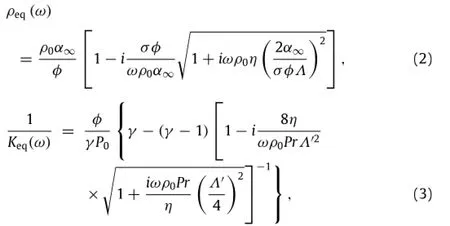
whereρ0andα∞denote the fluid density and tortuosity,φ the open porosity,σthe static airflow resistivity,ωthe angular frequency,ηthe air viscosity,Λ andΛ′represent the viscous and thermal characteristic lengths respectively,γthe specific heat ratio,P0the atmospheric pressure,and Pr is the Prandtl number. The JCA model consists of five macroscopic acoustic parameters: φ,σ,α∞,ΛandΛ′.
These macroscopic acoustic parameters are determined by the velocity field and property of fluid in fibrous material,which can be defined as

where the following symbol designates a fluid-phase average:

and the subscripts∗xdenote the x component.
The viscous boundary value problems were solved using finite element analysis at the micro-structure scale under both asymptotic low(f→0)and high(f→∞)frequencies,to deduce themacroscopicparametersintheequivalentfluidJCAmodel[15].
Using the solution of steady state Navier–Stokes(NS)problem, we can deducethelow-frequency limit(f→0)leading parameter (i.e.the static airflow resistivityσ).The NS problem is defined as

Here,∆ and∇ represent the local 2-d del and Laplacian differential operators,e is the unit vector,andΩfand∂Ωdenote fluid domain and fluid surface.In addition,w andπ represent a static velocity field and associated scalar pressure. As shown in Fig.3(a),we can numerically(including via the finite element method)solve the velocity field by imposing a noslip boundary condition at the fluid–solid interface and placing a periodic condition onπand w at the inlet/outlet surfaces.Once we get the solution for a given micro-structure,we can obtain the macroscopic static airflow resistivity by Eq.(4).
Comparing to the pore size,the boundary layer is small under extreme high frequency(f→ ∞),so we can ignore its viscouseffect.Similar to the electric conditions,the governing equations of sound propagation are defined as follows
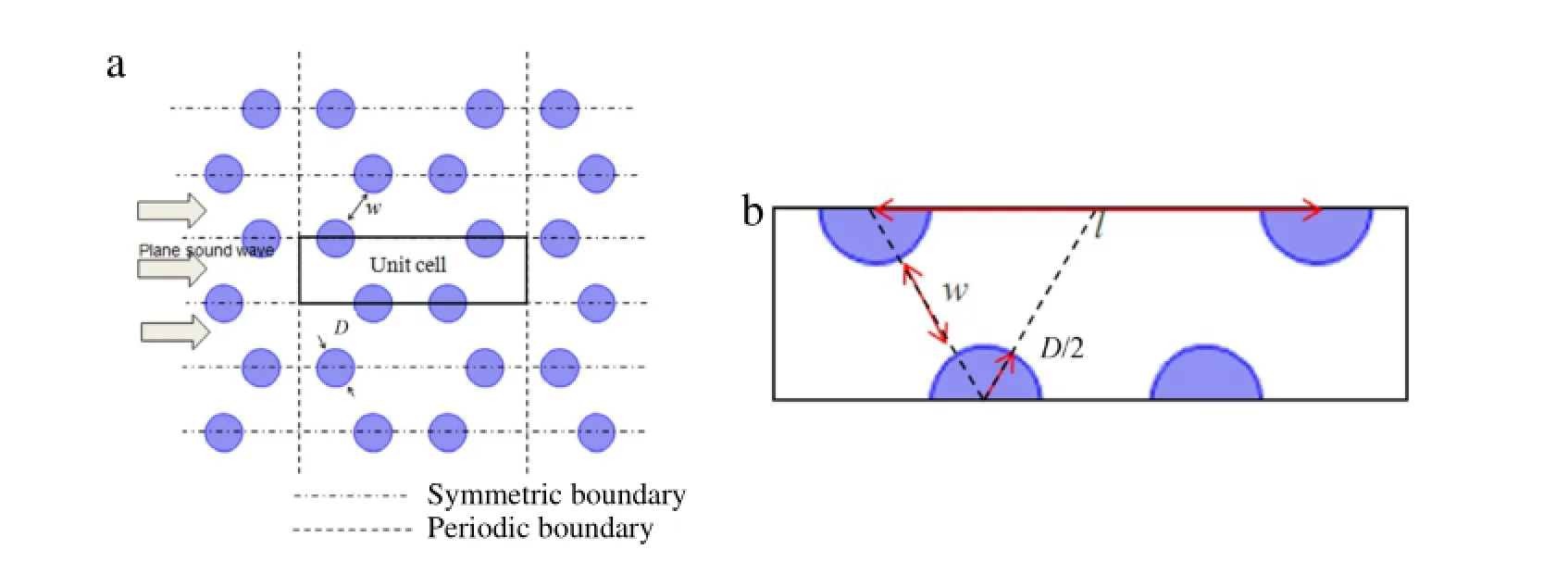
Fig.2.(a)Cross-sections of parallel fibers array;(b)Periodic micro-structure.

Fig.3.Velocity field at(a)low-frequency limit(f→0)and(b)high-frequency limit(f→∞).

Fig.4.Sound propagation in a multi-layered PFMs backed by an impervious rigid wall.

whereEandψdenotethevelocityfieldandpressure(similartothe electric field and electric potential)and n is the outward normal unit vector from the pore boundaries.Again,we can numerically solve the velocity field as shown in Fig.3(b).When the solution is obtained,we can use Eqs.(5)and(6)to determine the tortuosity α∞,viscous characteristic lengthΛ,and thermal characteristic lengthΛ′.
Table 1 lists properties of the air used in the following simulations.
Consider a multi-layered PFMs sample that is composed of n layers of PFM placed in series format as shown in Fig.4. In Fig.4,plane waves propagate in the opposite directionsparallel to the x-axis in the multi-layered PFMs sample backed by an impervious rigid wall.The sound propagation properties of the ith layer PFM are determined by ki(wave number),(characteristic impedance),and di(thickness).The wave number and characteristic impedance can be determined by the effective complex density and the bulk modulus of the ith layer PFM via[14]:

Table 1 Properties of air used in all studies.

The governing equation for harmonic plane wave propagation along the x-axis can be expressed as:

where piis the sound pressure of the ith layer.Two boundary conditions have to be satisfied at each layer interface:(a) continuity of the sound pressure and(b)continuity of the effective velocity.The solution of Eq.(11)in the ith layer is assumed as a superposition of forward and backward traveling waves:


Table 2 Some PFM samples[3].
By employing Eqs.(11)and(12)for the pressure and velocity, the impedance Ziat Mi(i.e.left boundary of the ith layer)is known and can be written as follows:

At Mi+1(i.e.right boundary of the ith layer),the impedance Zi+1 is given by

From Eq.(15),it follows that

Substitution of Eq.(16)into Eq.(14),the impedance translation theorem can be obtained.

As the multi-layered PFMs sample backed by an impervious rigid wall,the impedance at the surface of thewall is infinite.Then, by using Eq.(17),the total impedance at the surface of the multilayeredfibrousmetalZ1canbecalculated.Therefore,thereflection coefficientofthemulti-layeredPFMs’surfacecanbedeterminedas follows:


PFM’s sound absorption coefficient is calculated using an idealized and simplified hexagonal pore structure,and this pore structure and fibrous distribution are indeed different from the real PFM.In order to prove the validity of the proposed theoretical modelfor single-and multi-layeredPFMs,wecomparethepresent theoretical results with the experimental ones in Refs.[1,3].Four PFM samples and their geometric parameters are listed in Table 2. The samples all have the same diameter 50µm,but different thickness(10–25 mm)and porosities(73%–91%).As reported in Refs.[1,3],these four PFM samples were used in different assembling sequences to form four types of single-and multiplelayered porous structures as given in Table 3,which were tested for the measurement of sound absorption coefficient.The tested structures A and B are the single-layered PFM with PFM samples 1#and 2#respectively,structure C is composed of three layers of PFM in the order of PFM samples 2#,3#and 4#,and structure D is composed of two layers with PFM samples 4#and 2#.
Comparisons between the obtained results of the proposed model and experimental measurements are shown in Figs.5 and 6 for single-and multi-layered PFMs,respectively.Figure 5 shows that the predicted sound absorption coefficients for structures A andB(e.g.single-layeredPFM)matchwellwiththemeasuredonesin the low frequency range.For structures C and D(e.g.multilayered PFMs),there exists a small deviation between the computations and measurements as shown in Fig.6.This small deviation may be due to the idealized and simplified hexagonal pore structure and the simplified treatment of the transmission between the layers in our theoretical model or the inevitable micro-defects in the test samples.

Table 3 Four tested structures(the first layer is referred to the one that is closest to the incident sound resource(see Fig.4)).
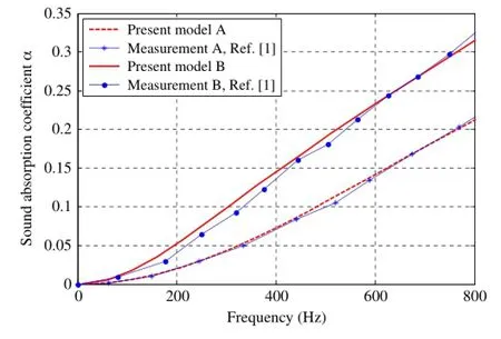
Fig.5.Sound absorption coefficient predicted and measured for single-layered PFM A and B.
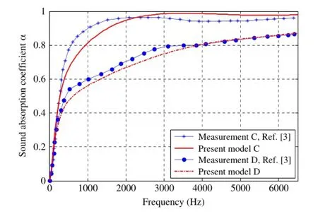
Fig.6.Sound absorption coefficient predicted and measured for multi-layered PFMs C and D.
We consider the optimum design of the pore structures (i.e.fiber diameter and gap)of multi-layered PFMs for enhancing the performance of sound absorption in the low frequency range. From the previous work[16],we can know that variation of fibergap can easily affect the sound absorption but fiber diameter’s change cannot.Therefore we choose the fiber gaps in each layer are the design variables,and keep the fiber diameter fixed as 50µm.The optimization model for maximizing the average sound absorption in the low frequency range(<500 Hz)is formulated as follows:

Table 4 The calculated macroscopic parameters and performance index of optimal four-layer PFMs(the first layer is referred to the one that is closest to the incident sound resource).
where n is number of layers,I denotes the average sound absorption coefficient index,L0is the absorber thickness(in this paper,we choose the thickness of absorber is 50 mm),α(fi) denotes the normal sound absorption coefficient computed at the ith frequency,and N is the number of discrete frequencies in frequency range of interest(here,we choose N=50 and the frequency intervalWe can use the finite difference method to derive the sensitivity of the objective function I to the design variableswias

Sequential linear programming(SLP)is used to solve the optimization problem(20).
A single-layered PFM with thickness of 50 mm and diameter of 50µmbackedwitharigidwallisconsidered.Thesoundabsorption index I in the low frequency range as a function of fiber gapw is calculated by using parameter analysis and is shown in Fig.7. In Fig.7,it is found that there exists a specific value of fiber gap (i.e.w=52µm)where we can achieve the optimal sound absorption performance index(i.e.I=0.301).The corresponding sound absorption coefficient for optimal single-layered fibrous material(as a function of frequency)is shown in Fig.8.
We aim to investigate the optimal fiber gaps of four-layer PFMs(Fig.9(a))for maximizing the sound absorption performance index I in the low frequency range.The thickness of material is 50 mm(same as single-layered PFM),and each layer has the same thickness 12.5 mm.The diameter is also chosen as 50µm. By solving the optimization problem(20),the optimal fiber gap distribution is achieved.The optimal fiber gaps from first layer to fourth layer arew1=40µm,w2=88µm,w3=75µm, andw4=64µm,respectively.The corresponding porosities are 81.3%,92.1%,90.3%,88.4%.Figure 9(b)shows the iteration history of the objective function and Fig.9(c)–(f)depict the sketches of pore structures of each layer.In this case,the optimal sound absorption performance index I is 0.358,which represents a 19.3% increasewhencomparedwithsingle-layeredfibrousmaterialwith the same diameter and thickness.The calculated macroscopic parameters and performance index are presented in Table 4. Figure 10 shows the sound absorption coefficient of optimal single and four-layer PFMs in the low frequency range(10–500 Hz).
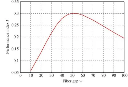
Fig.7.The sound absorption index I in the low frequency range as a function of fiber gapw.
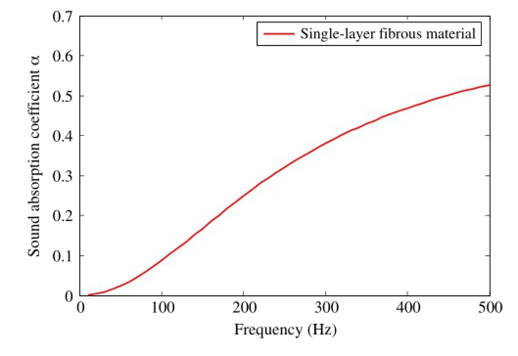
Fig.8.The sound absorption coefficient of optimal design of single-layered fibrous material.
It can be seen from Table 4 that the fiber gaps(or porosities) decrease along the sound incident direction except for the first layer in the low frequency range.To understand the effects of the first layer(surface pore structure)on the sound absorption performance of multi-layered fibrous metals,we perform a parametric study by considering the same multi-layered materials in Table 4 but with four different fiber gaps in the first layer.The different fiber gap in the first layer is chosen as 40µm,20µm,80µm,100µm(i.e.porosities are 81.4%,69.1%, 91.1%,93.3%respectively)whiletheotherthreelayersarethesame as fibrous metals in Table 4.These four cases with different fiber gaps in the first layer are denoted as S1,S2,S3,S4 respectively.
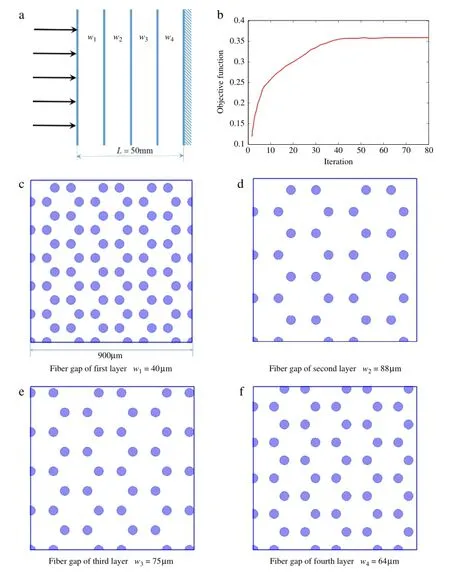
Fig.9.(a)Four-layer PFMs backed a rigid wall;(b)Iteration history of objective function;Optimal fiber gaps of each layer(c)first layer;(d)second layer;(c)third layer;(d) fourth layer.
Tocomparethesoundperformancesofthesefourmulti-layered structures,the average sound absorption coefficient index defined in Eq.(20)will be used.Table 5 presents the average sound absorption coefficient indexes of the four multi-layered structures in both low and mid-high frequency ranges.For the case in the low frequency range(10–500 Hz),case S1 has the optimal sound absorption performance.For the mid-high frequency range (500–5000 Hz),cases S3 and S4 have better sound absorption performances than S1.The detail sound absorption coefficient curves of the four multi-layered structures are present in Fig.11. It is obvious that the sound absorption coefficient of the multilayered PFMs increases with the frequency generally.It can also be noted that:(a)the sound absorption coefficient for case S2 with the lowest surface porosity is higher than other cases when the frequency is below about 130 Hz;(b)case S1 has the largest sound absorption coefficient when the frequency is in the range of 130–500 Hz;and(c)the absorption coefficient increases monotonically with the surface porosity when frequency is above~1500 Hz.It is believed that the acoustic resistance plays a major role for sound absorption in the low frequency range due to that a smaller surface porosity yields a higher acoustic resistance[14]. Although more acoustic energy can be dissipated by a higher acoustic resistance in porous media,most of acoustic energy is reflected when the surface porosity is too small.Therefore,an appropriate surface porosity of multi-layered PFMs can balance the dissipation and reflection of acoustic energy to maximize the sound absorption.
From Table 5 and Fig.11,it can be seen that the variation of the surface porosity has a significant effect on the soundabsorptionofmulti-layeredfibrousstructures.Generallyspeaking, an arrangement in the order of high porosity to low porosity along the sound incident direction is beneficial for improving the sound absorption in mid-high frequency range.However,this rule of porosity distribution cannot apply to low frequency range.

Table 5 The average sound absorption coefficient indexes of S1–S4.
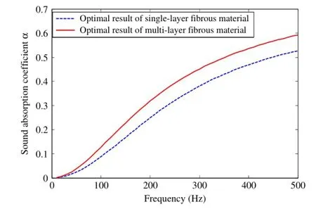
Fig.10.The sound absorption coefficient of optimal single and four-layer PFMs.
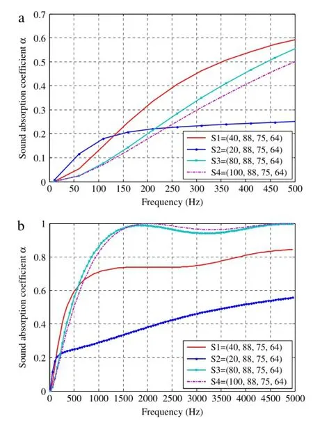
Fig.11.Sound absorption coefficient of four multi-layered PFMs with different fiber gaps of first layer.(a)10–500 Hz;(b)10–5000 Hz.
In this paper,an analytical model and a design method for multi-layered PFMs are presented for improving low frequency sound absorption.In the analysis model,the PFM is idealized and simplified as a periodic hexagonal arrangement of fibers aligned in one direction,and the sound absorption coefficient is determined based on the JCA acoustic model and impedance translation theorem;In the optimization model,the average sound absorption coefficient at low frequencies is chosen as the objective function andthefibergapsasthedesignvariables.Comparingthepredicted results with experimental data in the literature verifies that the analytical model is valid and effective.Numerical examples demonstrate also that the optimization model is applicable and efficient.The average sound absorption coefficient of optimal four-layered PFMs is 20%higher than that of the single-layered PFM with the same diameter and thickness in the low frequency range.Furthermore,the surface porosity of the multi-layered PFMs has a significant influence on the fibrous material’s sound absorption.Generally,increasing the surface porosity can improve sound absorption in mid-high frequency range but does not work for the low frequency range.The work presented in this paper would provide the references and guides for the future studies and manufacture of multi-layered PFMs.
Acknowledgments
The authors acknowledge the support of the National Basic ResearchProgram(973Program)ofChina(GrantNo.2011CB610304), the National Natural Science Foundation of China(Grant Nos. 11332004 and 11402046),China Postdoctoral Science Foundation (No.2015M571296),the 111 Project(B14013)and the CATIC Industrial Production Projects(Grant No.CXY2013DLLG32).
References
[1]H.Meng,Q.Ao,H.Tang,F.Xin,T.Lu,Dynamic flow resistivity based model for sound absorption of multi-layer sintered fibrous metals,Sci.China Technol. Sci.57(2014)2096–2105.
[2]Z.Bo,C.Tianning,Calculation of sound absorption characteristics of porous sintered fiber metal,Appl.Acoust.70(2009)337–346.
[3]T.Huiping,Z.Jilei,G.Yuan,W.Jianyong,L.Cheng,Sound absorbing characteristics of fibrous porous materials gradient structure,Rare Metal Mater.Eng.36(2007)2220.
[4]H.Ke,Y.Donghui,H.Siyuan,H.Deping,Acoustic absorption properties of open-cellAlalloyfoamswithgradedporesize,J.Phys.D:Appl.Phys.44(2011) 365405.
[5]J.E.Lefebvre,V.Zhang,J.Gazalet,T.Gryba,V.Sadaune,Acoustic wave propagation in continuous functionally graded plates:an extension of the Legendrepolynomialapproach,IEEETrans.Ultrason.Ferroelectr.Freq.Control 48(2001)1332–1340.
[6]M.Delany,E.Bazley,Acoustical properties of fibrous absorbent materials, Appl.Acoust.3(1970)105–116.
[7]M.A.Biot,Theory of propagation of elastic waves in a fluid-saturated porous solid.I.Low-frequency range,J.Acoust.Soc.Am.28(1956)168–178.
[8]D.L.Johnson,J.Koplik,R.Dashen,Theory of dynamic permeability and tortuosity in fluid-saturated porous media,J.Fluid Mech.176(1987)379–402.
[9]Y.Champoux,J.F.Allard,Dynamictortuosityandbulkmodulusinair-saturated porous media,J.Appl.Phys.70(1991)1975–1979.
[10]D.K.Wilson,Relaxation-matched modeling of propagation through porous media,including fractal pore structure,J.Acoust.Soc.Am.94(1993) 1136–1145.
[11]D.Lafarge,P.Lemarinier,J.F.Allard,V.Tarnow,Dynamic compressibility of air in porous structures at audible frequencies,J.Acoust.Soc.Am.102(1997) 1995–2006.
[12]W.Zhou,Y.Tang,M.Pan,X.Wei,J.Xiang,Experimental investigation on uniaxial tensile properties of high-porosity metal fiber sintered sheet,Mater. Sci.Eng.A 525(2009)133–137.
[13]R.F.Lambert,Propagation of sound in highly porous open-cell elastic foams, J.Acoust.Soc.Am.73(1983)1131–1138.
[14]J.Allard,N.Atalla,Propagation of Sound in Porous Media:Modelling Sound Absorbing Materials 2e,John Wiley&Sons,2009.
[15]C.Perrot,F.Chevillotte,R.Panneton,Dynamicviscouspermeabilityofanopencell aluminum foam:Computations versus experiments,J.Appl.Phys.103 (2008)024909.
[16]S.Liu,W.Chen,Y.Zhang,Design optimization of porous fibrous material for maximizing absorption of sounds under set frequency bands,Appl.Acoust.76 (2014)319–328.
28 September 2015
in revised form 24 December 2015
http://dx.doi.org/10.1016/j.taml.2015.12.002
2095-0349/©2016 The Authors.Published by Elsevier Ltd on behalf of The Chinese Society of Theoretical and Applied Mechanics.This is an open access article under the CC BY-NC-ND license(http://creativecommons.org/licenses/by-nc-nd/4.0/).
∗.Tel.:+86 411 84706149;fax:+86 411 84706149.
E-mail address:stliu@dlut.edu.cn(S.Liu).
*This article belongs to the Solid Mechanics
杂志排行
Theoretical & Applied Mechanics Letters的其它文章
- Editorial:Recent advances in mechanics of unconventional electronics
- The finite deformation of the balloon catheter
- Adhesion-governed buckling of thin-film electronics on soft tissues
- Mechanics of bioinspired imaging systems
- Recent development of transient electronics
- Recent advances on thermal analysis of stretchable electronics
