A review of cavitation in hydraulic machinery*
2016-10-18XianwuLUO罗先武BinJI季斌YoshinobuTSUJIMOTO
Xian-wu LUO (罗先武), Bin JI (季斌), Yoshinobu TSUJIMOTO
1. Beijing Key Laboratory of CO2 Utilization and Reduction Technology, Tsinghua University, Beijing 100084,China, E-mail: luoxw@tsinghua.edu.cn
2. School of Power and Mechanical Engineering, Wuhan University, Wuhan 430072, China
3. Graduate School of Engineering Science, Osaka University, Osaka, Japan
A review of cavitation in hydraulic machinery*
Xian-wu LUO (罗先武)1, Bin JI (季斌)2, Yoshinobu TSUJIMOTO3
1. Beijing Key Laboratory of CO2 Utilization and Reduction Technology, Tsinghua University, Beijing 100084,China, E-mail: luoxw@tsinghua.edu.cn
2. School of Power and Mechanical Engineering, Wuhan University, Wuhan 430072, China
3. Graduate School of Engineering Science, Osaka University, Osaka, Japan
This paper mainly summarizes the recent progresses for the cavitation study in the hydraulic machinery including turbopumps, hydro turbines, etc.. Especially, the newly developed numerical methods for simulating cavitating turbulent flows and the achievements with regard to the complicated flow features revealed by using advanced optical techniques as well as cavitation simulation are introduced so as to make a better understanding of the cavitating flow mechanism for hydraulic machinery. Since cavitation instabilities are also vital issue and rather harmful for the operation safety of hydro machines, we present the 1-D analysis method, which is identified to be very useful for engineering applications regarding the cavitating flows in inducers, turbine draft tubes, etc. Though both cavitation and hydraulic machinery are extensively discussed in literatures, one should be aware that a few problems still remains and are open for solution, such as the comprehensive understanding of cavitating turbulent flows especially inside hydro turbines, the unneglectable discrepancies between the numerical and experimental data, etc.. To further promote the study of cavitation in hydraulic machinery, some advanced topics such as a Density-Based solver suitable for highly compressible cavitating turbulent flows, a virtual cavitation tunnel, etc. are addressed for the future works.
cavitating turbulent flow, numerical simulation, turbopump, hydro turbine
Introduction
Cavitation is a very important hydrodynamic phenomenon occurring in many fields associated with liquid transportation. It is well known that hydraulic machinery usually suffers from severe vibration, noise,material damage, etc. due to cavitation. This is the reason why cavitation in hydraulic machinery has attracted our interests for decades.
Hydraulic machinery, such as pumps, hydro turbines, propellers, etc. is widely used in many sectors in our modern society. For examples, turbopumps are utilized in rocket engine system, circulating pumps are used for propellant transportation and heat control unit in a space station[1], 4 rotational ducted propellers and 1 tunnel propeller are utilized for China’s first deep manned submersible, Jiao-long[2], the first hydro turbine with huge capacity of 1 000 MW per unit has been developed for sustainable energy supply in the world[3],etc. For those hydraulic machines, the stable and safe operation is critical and should be carefully considered. Based on our experiences, the main causes of damage of hydraulic machinery are due to cavitation problems,sand erosion, material defects and fatigue, etc. Among those causes, cavitation is the most important issue which not only erodes the flow passage, but also induces flow blockage and violent pressure vibration. Generally, cavitation is very harmful to the hydraulic machinery and its system for deteriorating the operation quality and life. Therefore, cavitation has been an active topic for decades in the field of hydrodynamics,and its everlasting progress in mechanism findings and simulation techniques is expected.
To promote the research on cavitation in hydraulic machinery, few scholars summarized the relatedstudies. Arndt[4]tried to show a broad overview based on the state-of-art till 1980. He reviewed the physical phenomena of cavitation, and discussed the factors such as cavitation nuclei, surface roughness, viscosity,etc.. leading to the occurrence of cavitation and its impact on the performance of hydraulic machinery and hydraulic structures. Brennen[5]published a technical book, where unsteady cavitating flows, cavitation induced vibration and dynamic forces in pumps were introduced besides the basic cavitation related principles. Further, Tsujimoto[6]complemented the chapter titled by “Unsteady phenomena in turbomachinery” in the Japanese version, in which the author analyzed 1-D unsteadiness (surge and cavitation surge), 2-D unsteadiness (rotating stall and rotating cavitation),and their interactions in detail. Franc and Michel[7]explained the physical concepts and theoretical explanation for cavitation in their book. The book includes the contents of bubble dynamics and different types of cavitation, and is fairly good for understanding the general nature of cavitation. d’Agostino and Salvetti[8]collected nine lectures related to cavitation in turbopumps, such as the analysis and suppression of cavitation instabilities in turbopump inducers, rotordynamic forces acting on blades, etc..
The reviews for cavitation in hydro turbines are fewer compared with that in pumps. Avellan[9]demonstrated various types of cavity development related to different turbines, and the influences of the operating conditions such as load, head and submergence, etc. on cavitation. Escaler et al.[10]showed the structural vibrations, acoustic emissions and hydrodynamic pressures in several prototype turbines suffering from different types of cavitation. Kumar and Saini[11]discussed various aspects related to cavitation, different causes for the declined performance for the reaction turbines basing on literature survey. Since the drafttube-surge at part load seriously affects the limit of turbine operating range, extensive studies on the surge have been conducted. Nishi and Liu[12]introduced the related contributions on the following topics: a rational method for component test of a draft tube, nature of spiral vortex rope and its behavior in a draft tube,cavitation induced pressure fluctuations.
In the last two decades, the most remarkable progress must be the challenge of numerical simulation for cavitating flow in hydraulic machinery[13]. The numerical results involving the cavity evolution,vortex shedding, etc. as well as some visualization experiments enable us to have the insight into the nature of various cavitating flows. Though cavitating flows should be computed with a cavitation model based on assumptions, and some discrepancies between calculation and measurement are still observed[14], simulations are considerably helpful to evaluate the cavitating flows and cavitation performance instead of experimental investigations for hydraulic machines during design procedure. Thus, the authors would like to emphasize the recent progress of the study on cavitation in hydraulic machines. Furthermore, the methods for cavitation simulation, and the achievements based on the numerical calculations are focused.
1. Recent progresses for cavitating flow modeling
Most cavitation phenomena involve with turbulence. The numerical accuracy for cavitating turbulent flow simulation depends on both cavitation model and turbulence modeling method.
The present cavitation models in the literature can be classified into two categories: interface tracking and interface capturing procedures. Interface tracking procedures explicitly track and fit a distinct gas/liquid interface, and usually have the limitation to simple problems due to the great numerical difficulties of integrating through the interface for engineering applications. The interface capturing treatment, where the gas/liquid interface is obtained as part of the solution procedure, are more general in their applications and may be applied to both attached sheet cavitation as well as bubbly cavitation[15].
1.1 Homogeneous mixture flow model
The mixture cavitation model based on homogeneous flow assumption[16]is one of interface capturing cavitation models, and has been widely applied for the engineering practices in the industry of hydraulic machinery. A typical example of this kind of cavitation model has been developed by Schnerr and Sauer[17], where the physical properties of liquid-vapor mixture are described by Eqs.(1) and (2), and the cavitation process is governed by the mass transfer equation shown as Eq.(3).
The density of liquid-vapor mixture,ρ, is defined by

where the subscriptv means the vapor phase, and l means the liquid phase.αis the volume fraction of each phase.
The laminar viscosity of liquid-vapor mixture,µ,is defined by

The mass transfer equation related to cavitation is

whereu is the flow velocity. Two source terms, i.e.,andrepresent the evaporation and condensation effects during the phase change, and can be derived from the generalized Rayleigh-Plesset equation. Their definitions are expressed as:

If we consider the widespread application of hydraulic machinery, the machines may treat various fluids with large temperature variation, or cryogenic liquids. In those situations, the effects of fluid physical properties should be considered during cavitation simulation. Table 1 shows the physical properties at 1 atm for water with different temperatures. It is noted that there are obvious variations in viscosity as well as vapor saturated pressure with temperature changes.

Table 1 Physical properties of water at different temperatures
There are two ways to treat the cavitating flows with large temperature variations.
Yu et al.[18]directly considered viscous effect as well as the local variation of saturated vapor pressure,density, etc., and proposed a cavitation model (being named Yu’s model) based on the bubble dynamics, where the growth of bubble radiusis controlled by the simplified form of the Rayleigh-Plesset equation presented as Eq.(7). Note that the energy equation is applied to model the temperature distribution due to mass transfer in the model.


On the other hand, Zhang et al.[19]treated the flow at different temperatures based on the concept of thermal boundary between the bubble and bulk liquid. In the proposed thermodynamic cavitation model(being named Zhang’s model) involving the incompressible continuity equation, the momentum equation,and the energy equation, the process for vapor generation is divided into two stages:
First, the vapor growth is mainly controlled by the pressure difference between liquid phase and vapor phase as the conventional cavitation models. Once the bubble generation is developed, the further bubble growth will be dependent on the heat transfer from superheated liquid to the liquid-vapor interface. Thus,the source terms in Eq.(3) are as follows:


Fig.1 Pressure distributions along NACA0015 hydrofoil inwater at different temperatures
Figures 1 and 2 show the comparisons of the steady-state results predicted by different models for water at three temperatures. In the simulations, the cavitating flows over NACA0015 hydrofoil were treated with the above-mentioned cavitation models. The hydrofoil has a chord length of 0.115 m, and the angle of attack is. For the operation conditions, the inlet velocity i.e.is 8m/s, and the pressure at domain outletis designated based on the cavitation numberof 1.5. The pressure distributions along the hydrofoil are presented in Fig.1,where the pressure coefficient is defined to be

The results shown in Fig.1 demonstrate that both models can appropriately predict the thermodynamic effect on pressure distribution along the hydrofoil compared with the experimental data. At the room temperaturethe static pressure at hydrofoil leading edge is near the saturated vapor pressure due to the occurrence of the attached cavity there. With the increase of water temperature, the low pressure zones become much smaller due to the great shrinkage of the attached cavities as shown in Fig.2,where the cavity is presented by the area with vapor volume fraction larger than 10%. The vapor becomes shorter and thinner as the temperature increases. The results indicate that Zhang’s model predicts slightly longer vapor cavities due to larger mass transfer rates for evaporation than Yu’s model[18]at the temperatures of 25oC and 70oC.

Fig.2 Vapor cavity distributions along NACA0015 hydrofoil in water at different temperatures
It is noted that the numerical results by both models yield very similar cavitation features, and are basically reasonable. Since most thermodynamic cavitation models[19-21]should make use of thermal boundary assumption, Yu’s model naturally considering the effects of temperature on fluid physical properties, is preferable for engineering applications. 1.2 Three-component two phase flow model
Air admission is often used to reduce the drag for a moving under-water body, or to alleviate the material damage due to cavitation erosion, etc.. For those cases, since there are three fluid components in theflows, i.e., liquid, vapor and air/gas, the cavitating flows should be treated with special models.
Lindau et al.[22]proposed a cavitation model for simulations with air/gas admission. The mass transfer equations for both the vapor, and the air/gas are adopted as follows:
where the subscript g means the component of gas. Γ is the diffusion coefficient.ρ is the mixture density defined by

In the model, the effects of gas on cavitation process are represented by the source terms as follows:

To update the nuclei content in the flow field due to air/gas admission and emphasize the effect of air/gas content on cavitation, Ji et al.[23]suggested to use the source term for evaporation i.e., Eq.(18) instead of Eq.(16), because the gas contentcould affect the evaporation as the vapor volume fractiondid.

The revised model was applied to simulate the cavitating flow around an underwater body[24]. The numerical results reproduced the cavitation evolution,and indicated that the air admission promoted the cavitation development, and the vapor formed by nature cavitation was depressed rapidly as the experiment demonstrated.
For better understanding of cavitation with air/gas admission, Yu et al.[25]considered the interfaces between the liquid and the vapor/gas based on the Levelset method, and proposed a special three component cavitation model. The momentum conservation equation for the homogeneous flow is revised by adding a surface tension force term in Eq.(19).

This model has been used to simulate the turbulent flow over a cylindrical underwater body with natural and ventilation cavitation. The results depict that air admission can depress the vapor rapidly, and promote the steep growth of air cavity with the increasing air content. The comparison between the simulation and experiment showed good agreements, and verified that the simulation method predicted fairly well the cavitating turbulent flow with three components (water, vapor and air).
Among these cavitation models, Yu’s model can depict thermodynamic and viscous effects on cavitation development, and is suitable for most cavitating flows. Because the effect of surface tension is not considered in Yu’s model, the three-component two-phase flow model based on the Level-set method is better for the applications such as the ventilation cavitation in hydro turbines, cavitation at micro gravity circumstances, etc..
1.3 Turbulent flow modeling
There are many evidences that cavitation is a complicated phenomenon closely related with vorticity movement. Thus, turbulence modeling is an important issue for cavitation simulation.
As a popular approach, the Reynolds-averaged Navier-Stokes (RANS) method has been widely used for engineering turbulent flow computations. It is well recognized that RANS approach, such as thetwo-equation model, has the deficiency of over-estimating the turbulent viscosity when treating time dependent cavitating flows.
To improve the numerical simulation for cavitation, Johansen et al.[26]developed a filtered-based model (FBM) originated from theturbulence model. Wu et al.[27]adopted the model to simulate 2-D cavitating flows over the Clark-Y airfoil. The numerical results qualitatively agreed with the experimental data including lift, drag and velocity profiles. Further,Huang et al.[28]blended the FBM model to reduce the turbulent eddy viscosities in a turbulent cavitating flow, and the density correction model (DCM) according to the local fluid density, and proposed the filter-based density correction model (FBDCM). In FBDCM approach, which combines the merits of both DCM and FBM, the turbulent eddy viscosityis described as follows


Yu et al.[29]analyzed the unsteady turbulent cloud cavitation around a NACA66 hydrofoil with FBDCM. The results indicate that the transient pressure pulsation as well as the cloud cavity shedding frequency basically agrees with experimental results. The numerical simulations also indicate that the reduction of the turbulent eddy viscosity based on the meshing resolution and local fluid density tends to promote the vortex production and unsteady shedding of the cavities of the turbulent flows.
Another turbulence modeling approach, partiallyaveraged Navier-Stokes (PANS) method originally proposed by Girimaji[30]has been applied for cavitating turbulent flows recently[31,32].
In PANS method based on the standardtwo-equation model, the turbulent governing equations are shown in Eqs.(25) and (26), where the challenge is to determine the closure model as a function of the ratio of the unresolved-to-total kinetic energy i.e.,and that of the unresolved-to-total dissipation i.e.,defined in Eq.(28).


The application of PANS method was carried out for modeling cavitation around a NACA66 hydrofoil using different values of resolution control parametersIt is noted that cavitation is much steady at the case ofWith the decrease ofmore complicated cavitating flows are predicted by PANS method. The transient cavity oscillations during one vapor cloud shedding cycle are obtained and compared with the experiments. Those results indicate that the PANS approach withcan well reproduce the unsteady cavitation patterns as observed in experiments[31].
In engineering fields, especially at the simulationbased-design stage, RANS approach is the mainstream treatment for cavitating turbulent flows. The supplemented FBDCM improves the capability of RANS approach for the cavitation solutions with acceptable grid resolution and prediction error. Due to the inherent limitation, it is reported that RANS approach cannot reveal vast unknown temporal-spatial correlations in the multiphysics phenomena[33]. On the other hand,large eddy simulation i.e., LES is used for unsteady cavitating flows, and it is proved that LES is a promising approach to reproduce the complicated cavitation evolution and depict cavitation-vortex interaction[34]. Even there are very few attempts using direct numerical simulation i.e., DNS to treat a cavitating flow[35],the sufficient computation resource is necessary for DNS as well as LES, and DNS needs much more computing resource than LES. As a bridging model,PANS solver has the advantages of good simulation accuracy and affordable computation resource, and has been applied for some engineering cases[36].
2. Cavitation in pumps
Pumps are widely applied in various industries,and cavitation in pumps has been concerned near one century. Many concepts such as net positive suction head i.e., NPSH, cavitation number, suction specific speed, etc. have been introduced to evaluate the operation condition and suction performance for pumps[37]. Gulich summarized suction capability and cavitation for pumps in his technical book, where cavitation in impeller or diffuser, determination of the required NPSH, influence of the fluid properties, cavitationinduced noise, vibration and erosion, etc. are described and explained[38]. With the improvement of experimental techniques and simulation methods, people have achieved a lot to understand the flow mechanisms and promote design optimization for pumps.
2.1 Centrifugal pumps
Basically, cavitation in a centrifugal pump is simple, and usually occurs near leading edge of impeller blade. For the flow discharge less than the optimum design point, the flow is apt to separate at the suction side and generates a low pressure zone, where a cavity occurs as indicated in Fig.3. On the contrary,cavitation occurs at the blade leading edge of pressure side at higher discharge.

Fig.3 Schematic for leading edge cavitation in a centrifugal impeller
The prediction of cavitation inception and performance breakdown in centrifugal pumps is important for engineering application[39]. The simple treatment is to carry out numerical calculation with the quasi 3-D single passage. In the analysis, the numerical method is the RANS equations coupling with a homogeneous mixture cavitation model. The results can capture the principal physical elements of cavitation breakdown,where a significant two-phase region can be observed on the suction side, with an attendant large recirculation (re-entrant jet) at the aft end of the cavity[40-44]. Some unsteady flow simulations reveal that the main component of pressure pulsation at cavitation condition is due to the structural coupling between the impeller and the casing tongue, and had the same frequency as that of blade passing[45].
It is noted that there are discrepancies between the simulation and the experiment, such as the critical cavitation number, the gradient of performance breakdown curve, etc.. The present methods usually underestimate or overestimate the effect of cavitation on pump performance. Further, the simulated cavities had simple shapes without cloud shedding, and unsteady cavitation behavior remained unaddressed. To improve the accuracy, many researchers have conducted useful investigations, e.g., the staggered pressure discretization scheme as well as mesh adapting technique[46], the turbulent viscosity modification using liquid-vapor density[47], different empirical coefficients (the nucleation site radius, evaporation and condensation coefficients) in cavitation model[48], turbulence modeling with PANS[36], etc. Even with these efforts, the summary of cavitation simulations for centrifugal pump performance under cavitation conditions with several CFD methods indicates that the prediction accuracy for pump head drop and calculation stability should be improved further[49].
On the other hand, experimental study is necessary for understanding the cavitation evolution in a centrifugal pump. Besides pump performance test under cavitation condition, there are two important methods:visualization experiment and pressure fluctuation measurement. The visualization tests have been widely applied since the particle image velocimetry (PIV)technique was applied to measure the flow inside a pump by Dong et al.[50], where optical refractive index matching of the transparent flow passage component with that of the fluid is utilized as well as the flow tracer. Compared to the quantitative visualization i.e. PIV, high-speed video system can be used to investigate the unsteady behavior of leading edge cavitation by laser light-sheet and stroboscopic light illumination. An experiment using the high-speed video system was successful to catch two different stages of a cavitation cycle in a centrifugal pump with 2-D curved blades: (1 the larger extent of the shear cavitation on top of the attached part, (2) a smaller sheet cavitation and cloud cavitation, but no shear cavitation[42].
Rotating cavitation is a two-phase instability phenomenon, and affects the performance and reliability of centrifugal pumps. Rotating cavitation was first discovered in high speed rocket turbopump inducers. From then on, it has become a well known problem which has been analyzed by experimental and theoretical methods[51]. A similar effect in a centrifugal pump was reported in 1997. Several experimental investigations had been conducted from then on[52]. Those results depict a characteristic creeping head-drop curve compared to the usual sudden head-drop at normal operation conditions. The onset of rotating cavitation was assigned to the valueis the(whereα the incidence angle) of 2.5-2.8, and was mainly driven by an interaction of the cavity closure region and the following impeller blade[53].
Recently, the structural interaction has been concerned for a centrifugal pump, where there is fluidinduced rotordynamic force acting on the impeller,which is a combination of a steady radial force due to volute asymmetries and an unsteady force due to the eccentric motion of the rotor[54]. Compared to the noncavitating condition, cavitation corresponding to a head drop of three percent did not have a significant effect upon the unsteady force[55]. Due to the limited blade wrap angle, the rotordynamic whirl forces in radial impellers are much different from those in axial impellers. For the effect of impeller-tongue interaction on the unsteady cavitation in a centrifugal pump, the simulation showed that cavitation had the pulsation feature under off-design conditions, and was associated with the response of the vortex and uneven pressure distribution on volute[56].
In order to improve hydrodynamic performance,design optimization is necessary. The enlarged clearance between volute tongue and impeller up to about 20% of the radius at impeller exit successfully alleviated the noise induced by wake-jet flow structure at impeller exit. The attempt to improve the nonuniform outflow from the impeller by inserting additional short vanes i.e., splitter blade between regular blades reduced the original wakes, but generated an additional wake/jet phenomenon[57]. Note that splitter blades can influence cavitation performance for a double suction centrifugal pump. The results showed that the pump with splitter blades had lower required NPSH especially at high flow rate, and the improvement of cavitation performance would be attributed to better pressure loading distributions on blades due to the splitter blades[58].
For the centrifugal pumps, whose suction performance is strictly required, an inducer can be applied. To further reduce the required NPSH, a splitter-vane inducer is used to improve cavitation performance for a high-speed centrifugal pump[59,60]. The numerical results indicate that cavitation performance of the pump is much improved, and the main reason should be the increasing pressure upstream the main impeller. Besides, optimization of impeller inlet geometry[61],utilization of inlet guide vane[62], etc. are helpful to obtain uniform flow near impeller inlet and therefore improve cavitation performance of the pump.
2.2 Axial pumps and inducers
Generally, cavitation in an axial pump or inducer is much complicated than that in a centrifugal pump,because there is tip clearance between the impeller and the pump casing. Further, the effect of tip clearance is more significant on the performance of an axial impeller, since an axial pump has relatively small head,even compared to an unshrouded centrifugal impeller.
Figure 4 shows the possible cavitation patterns in a typical axial pump[5], where there are tip vortex cavity and backflow cavity due to the existence of tip clearance.

Fig.4 Cavitation types in an axial impeller
Usually, a laboratory test for axial flow pumps can be conducted using a water tunnel, or specially designed to insert an pump into a water tunnel[63]. Thiskind of test rig design is very helpful for the visual investigation and pressure oscillation measurement,and has been applied by many researchers. The experimental investigation for an axial pump includes high-speed video observation[64], dynamic pressure measurement, laser velocimetry measurement, flow field measured by PIV or SPIV, etc. so as to understand the cavitation development, pressure oscillation,axial and tangential velocity perturbation distributions,cavitation and tip vortex interaction, etc. Based on those experiments, the main achievements can be concluded: (1) Even in the operation range with negative slope of head-flowrate curve, a rotating choke occurred when the pump inlet pressure was decreased. The rotating choke induced large amplitude pressure oscillation with the frequency of half times of the shaft rotational speed and unbalanced peripheral pressure distribution[65]. (2) Sometimes there were two types of cavitation in the inducer: rotating cavitation and cavitation induced low cycle oscillation. For rotating cavitation, pressure oscillations upstream of the inducer were more severe than that downstream of the inducer. For cavitation induced low cycle oscillation, there were severe pressure oscillation both upstream and downstream of the inducer, and the cavity of each blade oscillated almost in unison[66]. (3) There was a critical tip clearance ratio (tip clearance divided by maximum blade thickness at tip section). For tip clearance ratio less than the critical value, cavitation likely appeared as surface cavitation on the tip section profile, and for tip clearance ratio larger than the critical value, vortex cavitation first appeared due to the flow through tip clearance zone[63]. (4) For the small tip clearances, the end-wall vortex originated near the leading edge, and for the large tip clearances the vortex originated near the trailing edge. Further, the normalized tangential velocity distribution downstream of the rotor trailing edge had the following features: for relatively larger tip clearance, it was similar to the laminar Burgers vortex model, for the intermediate tip clearance, it followed the Rankine model, as the blade-tip clearance further decreased, it appeared unlike either vortex model[67]. (5) The formation of tip vortex cavitation was affected by the pressure difference along the section profile of impeller blade, clearance geometry, gap height and tip sharpness, and tip vortex cavitation could be avoided by adjusting the flow rate out of the critical region[68]. (6) Among gap height, clearance, blade geometries and operating conditions, the gap height much affected clearance cavitation inception, and had less influence on tip vortex cavitation. The forward or backward blade skew may reduce or increase tip vortex cavitation respectively. There was an optimum clearance geometry to eliminate clearance cavitation when the clearance edge was rounded on the blade pressure side[69]. (7) A spiral-type vortex breakdown at the operation condition close to the stall was observed, and made the relative rotor flow highly unsteady. The stall phenomenon induced pump head drop to approximately 83 per cent of the peak value[70].(8) The tip leakage flow crosses the tip clearance passage with the vorticity generated at the blade tip. The development of tip leakage vortex (TLV) experienced several stages: at early stage, the vorticity rolled up near the corner of blade suction side, as the TLV detached from the blade, the leakage flow emerged as a wall jet and generated a train of vortex filaments connecting to the tip suction surface corner, and the TLV induced flow entrained this shear layer along with the endwall boundary layer, as well as the opposite sign vorticity[71-73].
The presently obtained experimental data are beneficial to the understanding of the distribution and circulation of vortices in the rotor passage, TLV evolution and the interaction of TLV and shear vortices. Based on these achievements, a schematic diagram is drawn to show the flows around the vane tip clearance in an axial pump or inducer as Fig.5.

Fig.5 Flows around vane tip clearance in an axial pump
Besides, the temperature effects on cavitation in a turbopump inducer has also been investigated[74]. The experiments indicated that the onset of rotating cavitation correlates with the start of the head coefficient degradation. For temperature lower than 340 K,the increasing temperature enhanced the hydrodynamic stability of the test inducer by suppressing the rotating cavitation. For temperature larger than 340 K,cavitation number corresponding to the onset of rotating cavitation remained unchanged.
In order to compare with the experiment and further depict the mechanism of cavitating flow, numerical investigations have been carried out for axial flow pumps[75], axial-flow pump blade cascades[76],propellers[77], etc.. Based on the corresponding results,the following can be summarized: (1) A linear equation was correlated to show the relation between the ratio of the tested to the predicted suction specific speed and averaged incidence angle corresponding to flow discharge. The results showed that the prediction error increased with the incidence angle[78,79]. (2) A correlation for predicting the vortex minimum pressure was proposed to identify an optimum tip clearance theoretically to depress leakage vortex cavitation[80],(3) The interaction between vane and tip vortex was not a primary cause of unsteady cavitation as indicated in some previous researches, but the negative flow velocity divergence due to cavity collapse much affected the flow incidence angle. At the operation with large flow coefficient, the backflow was weak, and the interaction with the cavity collapse was strong. As the flow coefficient decreased, there was stronger backflow, and the interaction between backflow, cavity collapse, and flow angle weakened[81]. (4) TLV dominated the end-wall vortex structures, and its size increased with the tip clearance. The tip leakage cavitation was enhanced and the angle between the blade chord and the TLV also increased with the tip clearance, but the propagation path of the TLV was nearly independent of the tip clearance in the downstream of the rotor or cascade. The TLV significantly changed the mean pressure and pressure fluctuations in the vicinity of the tip clearance zone. Though the smallest tip clearance resulted in minimum tip-leakage vortex and the cavitation, it was unclear what the optmal tip clearance for minimizing tip leakage cavitation was[82,83]. (5) In an axial flow pump, the TLV cavitation cloud was correlated with the TLV structure, and dependent on the blade chord fraction. The TLV induced suction-side-perpendicular cavitating vortices(SSPCV) oriented perpendicularly to the neighboring blade suction surface near trailing edge owing to the interactions of TLV and the trailing edge of the shed cloud cavitation on the suction surface at the part load condition. The SSPCV moved downstream and was cut off into two parts due to the next blade. This process triggered the cavitation instability, and the tip leakage flow and shear layer cavitation in the tip disappeared suddenly because of the rapid decrease in blade loading near the tip[84,85].
It is also identified that cavitation inception much influences the backflow structure[86]. Recent focus on the interaction of cavitation and vortex based on vorticity transport equation (VTE) demonstrates that cavitation promote vorticity production, the vortex dilation and baroclinic torque of VTE show a steep jump as cavitation occurs and vortex stretching is the main contributor to the large scale vortex generation for a water-jet pump[87].
It is obvious that numerical simulation has been indispensable for us to make clear the complicated cavitation phenomenon. In most cases, the qualitative agreement for the overall performance, cavity size and cavity location is obtained between experiment and prediction. Unfortunately, some limitations of numerical method can be found. For examples, the head breakdown in the simulations started at a different cavitation coefficient from that in the experiment[88],and the simulation did not correctly detect the vortex observed in experiment[89].
The tip vortex cavitation inhibition by drag-reducing polymer solutions was also investigated to suppress the effect of tip clearance in an axial pump[90,91]. Further, water injection into the core region of a tip vortex on an elliptical hydrofoil was tested. It was found that the optimal levels of water injection with the addition of polymer solution led to a reduction of 45% for the inception cavitation number, which was resulted from suppression of flow unsteadiness in the core region of the vortex. The active control is helpful for alleviating the unsteady TLV and its induced unfavorable phenomena in axial pumps and inducers[92].
3. Cavitation instability analysis for turbopumps
Cavitation instabilities lead to downstream and upstream pressure oscillation, and may be related to system instabilities[93-95]. Therefore, cavitation instability is so important for safe operation of hydro machines, a lot of experimental tests[96-99]and numerical researches[100-104]have been conducted extensively. In this article, both the physical phenomena and mechanism related to cavitation instability are discussed based on theoretical analysis[105,106].
3.1 Cavitation instabilities in inducers
An inducer is an axial flow pump used in the upstream of main impeller to avoid cavitation in the main impeller. It is generally operated with cavitation and often suffers from instabilities associated with cavitation. To minimize the head decrease due to cavitation, inducer impellers have a high solidity of around 2.0 at blade tip. Unlike other turbo-pumps, inducers are designed to have a certain incidence angle at the design point so that cavitation occurs only on the suction side. To secure the suction performance, the angle at blade leading edge measured from the tangential direction is very small, typicallyat blade tip. Both high solidity and large incidence angle causes strong secondary flow in the impeller and severe backflow at the inlet, resulting in lower hydraulic efficiency compared with other types of pumps. Rocket turbopump inducers are operated with high rotational speed to minimize their size and weight. To withstand high centrifugal force, the blades are usually stacked radially. All these features lead to the high risk of cavitation and instability in an inducer.
Based on the literatures, cavitation instabilities in inducers can be assorted into two types, cavitation surge and rotating cavitation[4].
With cavitation surge, the cavities on each blade oscillate in the same phase and the upstream and downstream flow rate fluctuates associated with the fluctuation of total cavity volume in the impeller. So,the frequency of cavitation surge depends on the upstream and downstream pipe length. This is somewhat similar to normal surge in pumps and compressors,which occurs at smaller flow rate where the head-flowrate curve has a positive slope. However, cavitation surge can occur even at the design flow rate where the performance curve has a negative slope[107]. This shows that the cause of cavitation surge is different from that of normal surge. Cavitation surge can occur above the cavitation number where the head starts to decrease caused by cavitation. These characteristics make the cavitation surge more serious since it may occur even at the design point.
With rotating cavitation, the cavity on each blade fluctuates with a certain phase difference. The phase difference is such that the cavity on the blade propagates from one blade to another in the same direction as the impeller rotation. Viewed in the stationary frame,the cavity rotates around the impeller at a speed faster than the impeller rotation[66]. This means that the rotating cavitation has larger frequency than pump shaft rotating frequency.
With rotating stall, the stalled region rotates around the impeller with a speed lower than the impeller rotation. Rotating cavitation occurs even at design flow rate and in the region of suction pressure where the head is not decreased by cavitation. This is the same as the case of cavitation surge. The total cavity volume in the impeller is kept nearly constant and the flow rate upstream and downstream the impeller is kept nearly constant. Rotating cavitation is not affected by the inlet and outlet pipe length and the frequency is proportional to the impeller speed.
3.2 Explanation of instabilities
In order to explain the cause of cavitation surge and rotating cavitation and to understand their relation to normal surge and rotating stall, one dimensional stability analysis[108,109]is carried out on a system shown in Fig.6.

Fig.6 A hydraulic system for instability analysis
The system is composed of an inlet pipe with the lengtha rotor, a tank, and the exit valve. Uniform flow of velocityis assumed for normal surge and cavitation surge, and sinusoidal disturbances with the wavelengths are assumed for the case of rotating stall and rotating cavitation. The velocity triangle at the blade inlet is shown at Fig.7, where the subscript 1 means the parameters at inlet, andh is the blade spacing. For convenience, cavities and blade cascades are shown in the same figure. In the impeller, it is assumed that the flow is perfectly guided by the blades. It is assumed that the cavity volumeoccurs at the inlet.

Fig.7 Velocity triangle at the blade inlet and cavities in blade cascades
Rotating cavitation, as well as cavitation surge, can be treated by assuming that the cavity volumeis a function of the cavitation number, (whereis the inlet pressureis the inlet relative velocity ) and the local incidence angle to the bladeis The normalized cavity volumea represented by

Then, the mass flow gain factorand the cavitation complianceare defined by

For 1-D instabilities of surge and cavitation surge,an axial velocity disturbance in upstream pipe of finite length is considered. For 2-D instabilities of rotating stall and rotating cavitation, a two-dimensional sinusoidal potential flow disturbance is assumed in the upstream of the impeller. In both cases the pressure fluctuation at the impeller inlet can be correlated with the axial flow velocity disturbance by applying the momentum equation to the inlet flow. This is why one-dimensional stability analysis is possible also for two-dimensional instabilities such as rotating stall and rotating cavitation. The pressure increase in the impeller is obtained by assuming that the flow in the impeller is perfectly guided by the blades. To simulate surge and rotating stall, two types of loss are assumed: an incidence loss proportional to the loss coefficientand the square of the incidence velocityat the inlet, and a through flow loss proportional to the loss coefficientand the square of the flow velocitythrough the impeller flow channel.

Table 2 The onset condition and the frequency of instabilities in turbo machines
The effect of cavitation is taken into account in the continuity relation across the impeller by representing the cavitation characteristics byand. If we represent the axial velocity disturbance at the inlet and the outlet of the impeller byand, respectively, and represent the cavity volume per blade by, the continuity equation across the impeller can be expressed by

As the cavity volume is a function of the cavitation numberand the incidence angleshown in Eq.(32), the cavity volume fluctuation can be represented by

The effect of cavitation on the pressure performance of the impeller is neglected since most of cavitation instabilities occur in a range where the pressure performance is not affected by the existence of cavitation.
To obtain simple expressions of the onset condition and the frequency of surge, cavitation surge, rotating stall and rotation cavitation, various simplifying assumptions are made for each instability: (1) For cavitation surge and rotating cavitation, it is assumed that the downstream flow rate fluctuation does not occur. This is a good approximation for typical inducers with a smaller blade angle. (2) For surge, it is assumed that the flow from the rotor is discharged to a surge tank followed by an exit valve. (3) For rotating stall, it is assumed that the flow from the impeller is discharged directly to a space of constant pressure.
By writing down the relations connecting the flow disturbances in the upstream and the downstream of the impeller, we obtain a set of linear equations in terms of the amplitudes of fluctuations. From the coefficient matrix of the linear equations, we obtain a polynomial characteristic equation in terms of a complex frequency whose real part represents the frequency and the imaginary part represents the damping rate of possible instability mode.
The onset conditions and the frequencies obtained by solving the characteristic equations are summarized in Table 2. The symbols in the table are as follows:is the static pressure coefficient of the impeller.is the flow coefficient, with the mean axial velocityand the circumferential velocity of the impeller
Greitzer’s B factor is calculated by

The results shown in Table 2 show the following features:
(1) Both surge and rotating stall occur at small flow rates with a positive slope ofcharacteristic curve. Under this condition, the head produced by the rotor will increase if the flow rate is increased which accelerate the flow and results in further increase of the flow rate. This positive feedback is the cause of surge and rotating stall.
(2) Both cavitation surge and rotating cavitation occur when
(3) The frequency of surge is basically identical to, the natural frequency of a Helmholtz resonator composed of a tank with the complianceand an inlet pipe with the lengthand does not depend on the impeller speed.
(4) The frequency of cavitation surge is proportional to the impeller speedand inversely proportional to the square root ofand. This shows that cavitation surge is an oscillation of the upstream fluid associated with the compliance of cavitation in the impeller.
(5) The propagation velocity ratio defined asfor rotating stall is less than 1, suggesting that the stalled region rotates slower than the impeller.
(6) Two modes of rotating cavitation are predicted. One of them rotates faster than the impeller and this mode is generally observed in experiments[110]. The other mode rotates slower than the impeller and occasionally observed as a mode rotating in the opposite direction of the impeller.
When the flow rate is increased, the angle of attack to a rotor blade is decreased. If the value of mass flow gain factoris positive, the cavity volume will also decrease from the definition of mass flow gain factor. If the cavity volume is decreased, the inflow to the rotor will increase to fill up the space occupied by the cavity volume decreased. Thus, the increase of flow rate results in further increase of flow rate. This mechanism of instability depends totally on the continuity relation and is not associated with impeller performance. Actually, both rotating cavitation and cavitation surge occur at a higher inlet pressure where the performance degradation due to cavitation is insignificant.
On the contrary, positive cavitation compliance has an effect to suppress instabilities: when the inlet flow rate is increased, the inlet pressure will decrease due to the Bernoulli effects and the cavity volume will increase if, resulting in the decrease of the inlet flow rate. Thus,provides negative feedback and stabilizes the system. The onset condition of cavitation surge and rotating cavitation does not depend on the steadyperformance and they may occur even at the design flow rate. This makes the cavitation instabilities more serious than surge and rotating stall that occur at off design points. The mechanism of instabilities in turbopumps is summarized in Fig.8.
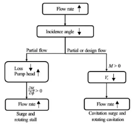
Fig.8 Mechanism of instabilities in turbopumps
Although not treated in this article, there exists cavitation instabilities caused by the positive slope of the characteristic curve resulted from the blockage effects of cavitation[111,112]. These instabilities occur at smaller cavitation number where the cavity extends into the passage between blades. These conditions are not used as the design point but we should be careful so that the operation point does not fall into this region.
4. Cavitation in hydro turbines
There are largely two types of hydro turbines, i.e.,reaction turbine and Pelton turbine. Though cavitation has been rarely discussed for a Pelton turbine, the needle valve of a nozzle and turbine bucket are apt to suffer from severe damage due to cavitation[113,114]. For a reaction turbine, cavitation has been an important issue for decades, and should be carefully considered during hydraulic design and prototype operation. It is clear that the runner design influences cavitationinception and development besides the operation conditions such as the machine setting level and the operating point.

Fig.9 Typical performance diagram of a Francis turbine with a high specific speed
4.1 Cavitation features in hydro turbines
Since hydraulic stability as well as cavitation depends on the operation conditions, Fig.9 shows six typical operation zones for a high specific speed Francis turbine[115]. Note that the guide vane opening is indicated by the solid dash line in Fig.9, where different openings are marked with a1-a9. The features for these operation zones are as follows:
(1) At Zone 1, the flow at runner outlet has a circulation in the direction of runner rotation. Because of low load and very low efficiency, the turbine should not be operated.

Fig.10 Vortex ropes at different operation zones
(2) Zone 2 is a partial load operation area, where the turbine is not allowed to be operated at a long period. There is the predominant pressure fluctuation with a low frequency[116]as well as discharge oscillation[117]due to helical vortex rope in draft tube shown in Fig.10(a). The vortex rope is generally filled with cavitation since the pressure there is lower. According to Rheingans[118], the frequency of pressure fluctuation is calculated by

(3) Francis turbines are usually operated at Zone 3 and Zone 4, where Zone 3 is a high partial load operation zone with 65%-90% of optimal flow, and Zone 4 is the optimal efficiency operation zone. In Zone 3, there can have pressure fluctuation with frequency higher than rotating frequency. In Zone 4,there is no vortex rope in the draft tube, and the operation is stable.
(4) Zone 5 is the full load operation zone, where a cylindrical vortex rope with inverse runner rotation can be observed as shown in Fig.10(b). In full load conditions, self-oscillations may occur[119]. These selfoscillations are experienced with an axial pulsation of the cavitation volume corresponding to the first eigen frequency of the system[120]. The onset of full load pressure surge may cause pressure and power oscillations. The hydro-acoustic and modal analysis can be used to illustrate the self induced oscillation nature of the full hydraulic circuit[121].
(5) In the overload zone, i.e., Zone 6, both cavitation as well as pressure fluctuation increases. Sometimes, a second vibration occurs[115].
Among those zones, the vortex rope phenomenon has been extensively discussed, which occurs at both partial load and full load conditions[122,123]. At partial load, the vortex rope develops from the runner cone and wraps around the dead water region at the center of the draft tube. It is also well recognized that the geometry of vortex rope depends on the operation load (flow coefficient), though the rope diameter is dependent on cavitation number.
The great risk of a high amplitude pressure fluctuation in prototype turbine operation is due to the resonance between the vortex rope rotation and the natural oscillation of the water in draft tube when their frequencies become close to each other. The natural oscillation frequencyis expressed as

To further investigate the vortex rope at partial flow operation of hydro turbines, flow visualization by particle image velocimetry[124], laser Doppler velocimetry (LDV)[125,126], unsteady wall pressure measurement[127,128]and simulation model test[129]have been conducted to extract both the periodic velocity components and the rope dimension. The results[124]indicate that the rope diameter as well as diameter oscillation increases with the decreasing cavitation number. The vortex position variations demonstrate that the vortex at partial load has a kind of precessional motion,whose eccentricity increases downstream since the diameter of dead water region increases downstream.
Besides swirling cavity (i.e., vortex rope), several types of cavitation should be discussed. Figure 11 shows leading edge cavitation, inter blade vortex cavitation and traveling bubble cavitation in hydro turbines.

Fig.11 Three types of cavitation in Francis turbines
Leading edge cavitation is likely to occur in Francis turbines. However, leading edge cavities can sometimes be observed at the inlet of the Kaplan turbine runner even at the case of on cam operation[7]. The leading edge cavitation is sensitive to the energy coefficientrather than cavitation number. As shown in Fig.12, the high or low levels of energy coefficient correspond to cavitation onset at the leading edge suction side or pressure side of the runner blades respectively for both Francis turbines and Kaplan turbines.
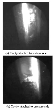
Fig.12 Leading edge cavitation in Francis runner (courtesy of DEC)
Inter blade vortex cavitation[130]can attach to the intersection of the blade inlet-edge with the crown or mid-way of the crown between the blades close to the suction side. The vortex cavitation may be originated from the complex flow recirculation at the inlet of the runner at partial load operation[7]. Another explanation is that the inter blade vortex cavitation is formed by secondary vortices located in the channels between blades that arise due to the flow separation provoked by the incidence variation from the crown to the band[8].
For traveling bubble cavitation[131], it is a cluster of separated bubbles attached to the blade suction side near the mid-chord next to the trailing edge. These bubbles appear due to a low plant cavitation number. Traveling bubble cavitation is very sensitive to the cavitation nuclei content and cavitation number. Thus,the plant NPSH should be determined with consideration of traveling bubble cavitation. The efficiency drop is noticed when cavities extend to the runner outlet. The cavities grow with load, reaching the maximum when the machine operates in full load condition with the highest flow rate[8].
Von Kármán vortex cavitation is shed from the trailing edge of runner blade or stay vane. The frequency and amplitude of the von Kármán vortices are highly dependent on the free stream velocity and the trailing edge profile of the vane[132]. When this excita-tion frequency coincides with one of the natural frequencies of the hydro turbine, resonance occurs, causing vibration and potentially initiating cracks for the machine, especially for low head turbines such as Kaplan or tubular turbines[133]. Ref.[115] shows the evidence of Von Kármán vortex cavitation, an eroded zone like “cat ear” in a Francis turbine. Thus, it is important to check that the vane natural frequency do not match the vortex shedding frequency.
For Kaplan turbines, two types of the cavitation often occur: tip clearance cavitation and tip vortex cavitation. The tip clearance cavitation occurs in the tip clearance due to high leakage flow in the clearance. So, it depends on the pressure difference between pressure and suction side of the blade. The flow in the clearance could be very fast, and the high velocity is linked to the decrease of the pressure.
The tip vortex cavitation is also originated from the clearance flow. When the tip clearance flow leaves the gap between the runner casing and the blade tip, a jet is created. The shear layer between the leakage jet and the main flow rolls up and creates the tip vortex at the end of the jet. The tip vortex starts near the leading edge of the blade, detaches the blade suction side surface and develops downstream along the runner blade. Usually, a longwise wavy shape can be observed for the vortex[134].
Both types of cavitation are not very dependent on cavitation number. They do not cause the efficiency drop of the turbine, compared with those dangerous cavitation phenomena such as surface cavitation,hub cavitation, leading edge cavitation, etc. But special attention should be paid because they can cause severe cavitation erosion for runners of Kaplan or tubular turbine.
Thus, hydro turbines have many types of cavitation, and each type of cavitation originates from different flow conditions. For most cases, there may be several types of cavitation in a turbine at one certain operation condition. This is the reason why the cavitating flows as well as its effects on machine performance are not easy to be quantitatively predicted with satisfactory accuracy by numerical simulations.
4.2 Draft tube surge modeling
As mentioned in last section, vortex rope phenomenon in the draft tube of hydro turbines has been excessively studied due to its very harmful effects on a turbine or a hydropower plant. For decades, great efforts have been made to make clear the flow mechanism of vortex rope and the suppression of the pressure surge in turbine draft tubes.
Besides the experimental investigations[135,136],lots of numerical analyses have been conducted to find out the flow features in the draft tube. The general works are the flow simulations in whole passage of a hydro turbine based on Navier-Stokes equation coupling with or without cavitation model. Among those studies, the most are carried out using commercial codes[137-140], and few are realized by OpenFOAM free source software[141]. The velocity distribution, flow pattern and pressure fluctuation in draft tubes under surge conditions are comprehensively studied. Those results indicate that the numerical simulation can capture the vortex rope behavior and low-frequency pressure oscillation in draft tube fairly well, and the strong pressure fluctuation can propagate to the gap between runner and guide vane[142]. Further, the uneven flow field caused by spiral vortex leads to the asymmetric cavitation development[143].
Some useful trials have been done for huge savings in both computing time and resources in the full 3-D flow simulation from the viewpoint of industrial application. A 2-D axisymmetric model is applied to numerically predict the mean flow field in a draft tube operating under partial load. For compensation of the lack of circumferential derivatives, a stagnant region model is introduced, where a unidirectional circumferentially averaged meridian flow is artificially suggested based on the experimental data, to modify the axisymmetric turbulent swirling flow[144]. It is confirmed that the 2-D axisymmetric model can give the average location of the vortex rope, and be used for further stability analysis, as well as for assessing and optimizing various techniques to stabilize the flow in draft tubes. The 2-D model underestimated the turbulent kinetic energy production and diffusion near the draft tube center, resulting in incorrect calculation of turbulent kinetic energy profiles and poor prediction of the axial velocity[145]. Of course, the 2-D method cannot capture the unsteadiness of the complicated 3-D flow in the draft tube of a hydraulic turbine operating under off-design condition.
Theoretically, 1-D stability analysis can also be used to determine the cause of the draft tube surge[146]for hydro turbines. In the analysis for a hydraulic system composed of a penstock, a runner and a draft tube, the cavity volume is assumed to be a function of the pressure at the vortex core, which is evaluated from the instantaneous local pressure at the runner exit and an additional pressure decrease due to the centrifugal force on the swirling flow. The results indicate that the diffuser effect of the draft tube has a destabilizing effect at all flow-rate conditions, while the swirl effects stabilize the system at larger flow rates, and destabilize the system at smaller flow rates[147]. It is also revealed that the oscillation frequency for flow discharge is determined from the compliance of the cavitation and the inertial length of the draft tube.
4.3 Draft tube surge suppression
To avoid the unfavorable effects of vortex rope,there are largely three groups of method for draft tubesurge suppression.
The first group is to optimize the turbine geometry if the replacement of turbine runner or draft tube is possible. Through design optimization, better hydraulic efficiency and pressure fluctuation alleviation can be obtained by securing the sufficient meridional flow near the crown side even at the partial load[148], mitigating the velocity distortion in the elbow part, decreasing total pressure loss[149], etc.. With the help of multi-objective genetic algorithm, the design optimization has become much effective method to improve the hydraulic performance and control the unsteady flow in the draft tube[150].
For the cases that the turbine runner is not allowed for replacement, people can use some flowcontrol structures to suppress the pressure oscillation in a draft tube. Because the pressure oscillation results from the vortex rope whirl, it is possible to mitigate the pressure fluctuation by applying suitable structures to weaken the swirl flow. It is verified that the optimization of runner cone shape[151], fin installation inside the draft tube inlet[152], runner cone with vortexcontrol groove[153], etc. are possible to depress the vortex rope phenomenon.
Because there is a stagnation zone with low pressure in a draft tube, the fluid admission with high pressure is regarded as the third group of the applicable methods to mitigate the pressure surge at partial load condition. Because the pressure at this zone is low, the ventilation with the nature air is preferable for the operations of prototype turbines.
Air ventilation can be introduced at the spiral casing, the annular chamber between the guide vane and the runner, the runner band, the runner crown cone or a snorkel attached to the runner cone, the draft tube wall, etc.. It is reported that the location and volume for air ventilation affect the amplitudes of pressure oscillations, but hardly affect the oscillation frequencies[154]. It has been confirmed that the air admission with suitable volume has preferable effect for pressure surge suppression in a draft tube[155].
Instead of air ventilation, water admission from the tip of runner cone axially in the inlet cone of a draft tube was proposed to eliminate the stagnation of swirling flow in a draft tube[156]. It is reported that the jet control of the swirling flow effectively removes the vortex breakdown at partial load. Compared with air jet, water jet has much larger momentum and is effective in elimination of the stagnant region in a draft tube operating at part load conditions[157]. The water jet supplied from the high-pressure flow upstream of the turbine spiral case by a bypass line increases the axial momentum of flow at the center of the draft tube,decreases the wake of the crown cone and thereby decreases the shear at the interface of the stagnant region and high velocity outer flow[158,159].
Generally, there are several requirements and guidelines for a successful vortex rope control technique[157,160]: (1) The cause of the vortex rope formation should be addressed clearly, (2) It is better to control the vortex rope at the inlet of the draft tube, (3) The control should focus on the stagnant region near the center of the draft tube rather than the swirl near the wall, (4) It is necessary to pay attention to the influence on hydraulic efficiency over all operation conditions whatever methods are applied to mitigate the pressure surge in a draft tube.
At last, it should be addressed that the cavitating turbulent flow simulation in hydro turbines is more difficult than that in turbo pumps, because a hydro turbine has the much more complicated flow passage geometry and large domain size. Once cavitation model is triggered, the simulation may become further more unstable. Thus, there are hardly actual applications of advanced cavitation model and turbulence modeling methods such as PANS, large eddy simulation i.e. LES, etc. for the flow simulation in hydro turbines, though very few attempts have been carried out for the cavitating turbulent flow simulation in a centrifugal pump, whose geometry is relatively simple.
5. Future works
In spite of the amazing progress in the study on cavitation in hydraulic machinery, further improvement is still necessary for both experimental and numerical methods.
Considering the engineering application, the suitable cavitation model and turbulence model should be optimized so as to achieve acceptable prediction accuracy. At present, numerical simulation can roughly reproduce cavitation phenomenon, some complicated flows are not predicted appropriately. The main reason may be the widely applied Pressure-Based CFD solvers for cavitating flows, which actually include highly compressible gas/air and vapor components. The pressure-based solver uses the incompressible Navier-Stokes equations and is formulated as mixed ellipticparabolic type equations. In cavitation area, the compressibility is remarkable, so the pressure correction equation for the pressure-based algorithm needs some revision to achieve solutions for the cavitating flow,which makes the fluid density be corrected to account for the strong pressure-density dependency[161]. Unlike the incompressible Navier-Stokes equations, the compressible Navier-Stokes equations have a time-derivative term in their continuity equation and are formulated as mixed hyperbolic-parabolic equations. This change in equation makes a significant difference in terms of suitable numerical schemes and can make us to refer to some recent CFD development of aerodynamics, i.e., shock wave simulation. Thus, a suitable density-based solver is expected.
As for cavitation model, an incorporated expre-ssion is expected instead of several types of specified models, and can be suitable for various applications. As for turbulence modeling, LES or PANS method may be a promising approach. Instead of the fixed ratios of unresolved turbulent kinetic energy and dissipation rate, suitable dynamic resolution control parameters for PANS approach are necessary to obtain reasonable cavitating turbulent flows. Cavitating flow simulation by LES is a hot topic for the recent cavitation simulation[162-169]. Most of these works selected the simple geometry, e.g., hydrofoil, Venturi-type section. The mesh resolution is very important for the successfully cavitating flow simulation by LES and we need to ensure that the predicted turbulent kinetic energy spectrum obeys the Kolmogorov -5/3 law,which is essential for LES methods.
Besides, it is noted that it is a key point to develop an effective parallel algorithm for CFD cavitating flows as engineering applicability needs a lot of computing resources. According to our recent research,traditional parallel algorithm of CFD might not be valid for cavitating flow simulation as the data in each part is not exchanged timely during the inner iteration. This might be another interesting topic for cavitating flow simulation.
In order to further promote the numerical simulation for hydraulic machinery, a virtual cavitation tunnel is necessary with the help of high-performance computing technology in the future. The virtual tunnel can be based on a series of high-fidelity CFD solvers,and need many obligatory studies such as experimental validations and verifications by actual problems,etc. These CFD solvers may be constituted by using open source software, e.g., OpenFOAM. We should be aware that the development of the virtual cavitation tunnel suitable for the engineering applications in hydro machines is a very important challenge, and need the long-term and great efforts contributed by academic people and industries.
Though the experimental measurement methodology is not addressed in the present paper, it is urgently required to explore the techniques of pressure measurement on blade surface, internal flow visualization, etc. with better accuracy and without the disturbance to the actual flow condition. Regarding to experimental investigations, the advanced unsteady 3-D PIV techniques are needed to depict the internal flow and its rapid evolution in hydro machines. Another optical tool for cavitating flow measurement, laser Doppler velocimetry (LDV) has been applied for centrifugal pumps[170,171], step flow[172], etc., since LDV can measure the velocity and its vibration with good accuracy and fast response. Based on the same Doppler principle, the technique of planar Doppler velocimetry (PDV), also referred to as Doppler global velocimetry (DGV) has been developed and used for measuring the flow of a rotating disk[173]. The recent application of a semiconductor laser instead of the expensive Nd: YAG laser makes the experiment setup of PDV much smaller in size, and cheaper. Though there are very few achievements reported in literatures related to cavitating flow measurement, PDV is a suitable method for cavitation study because the tiny bubbles or nuclei are good tracers for imaging the flow field. It should be noted that we sometimes have to choose PDV/DGV or PIV due to their overlap function for visualization experiments.
The accurate pressure measurement for rotor blades is under development by using wireless signal transportation, and may be applied widely for laboratory test and on-site operation measurement.
Finally, further study on hydrodynamic design and operation optimization of hydraulic machinery will be developed based on the better understanding of internal flow features.
6. Concluding remarks
The present article basically concentrates on the recent progresses on cavitation and its related issues in hydraulic machinery. Thank to the remarkable improvements for experimental and numerical techniques,the mechanisms of complicated cavitating turbulent flows in hydro machines have been revealed or partly revealed. On the other hand, the limitation of cavitating flow simulation and the discrepancies between numerical prediction and experimental measurement are also addressed.
Five topics are mainly involved:
(1) The numerical methods of cavitating turbulent flow simulations are discussed, including cavitation models suitable for large temperature variation and three-component two-phase flows, and turbulence modeling methods based on the literatures published within recent years.
(2) Several advanced issues such as unsteady behavior of leading edge cavitation, rotating cavitation,structural interaction and rotordynamic force under cavitation conditions, etc. are demonstrated for centrifugal pumps. Regarding to axial pumps, the interactions among tip clearance flow, vortex and cavitation are shown using both visualization experiment and numerical simulation results.
(3) The various types of cavitation in hydro turbines are demonstrated, and the achievements related to rope vortex and pressure surge in draft tube have been extensive explained. Besides, the active control methods are introduced so as to alleviate the induced pressure fluctuations.
(4) Turbopump inducers are used to illustrate cavitation instabilities and summarize the mechanism of instabilities in hydro machinery. The onset condition and the frequency of instabilities can be predicted by 1-D analysis method fairly well.
(5) Some advanced numerical approaches or platform, such as a Density-Based solver suitable for highly compressible cavitating turbulent flow simulation, a virtual cavitation tunnel, etc. are expected for the further promotion of the cavitation study in hydraulic machinery.
It should be mentioned that the study on the unsteady cavitation phenomena in the pump turbine(reversible turbine) is very important for our sustainable energy supply systems, especially in China. One can get the understanding by referring to the part about centrifugal pump, since the cavitating turbulent flow in the pump turbine operated at pump mode has the similar feature with that in a centrifugal pump. Beside,a recent review on the rotating stall in reversible pump turbines is available[174].
References
[1] LUO Xian-wu, ZHU Lie and ZHUANG Bao-tang et al. A novel shaft-less double suction mini pump[J]. Science China Technological Science, 2010, 53(1): 105-110.
[2] LIU Feng, CUI Wei-cheng and LI Xiang-yang. China’s first deep manned submersible, JIAOLONG[J]. Science China Earth Science, 2010, 53(10): 1407-1410.
[3] LU Li, LIU Juan and YI Yan-lin et al. Evaluation on sand abrasion to Baihetan hydraulic turbines[J]. Journal of Hydroelectric Engineering, 2016, 35(2): 67-74(in Chinese)
[4] ARNDT R. E. A. Cavitation in fluid machinery and hydraulic structures[J]. Annual Review of Fluid Mechanics, 1981, 13: 273-328.
[5] BRENNEN C. E. Hydrodynamics of pumps[M]. Norwich,VT, USA: Concepts ETI Inc., 1994.
[6] BRENNEN C. E., TSUJIMOTO Y. Hydrodynamics of pumps[M]. Osaka, Japan: Osaka University Press, 1998.
[7] FRANC J.-P., MICHEL J.-M. Fundamentals of cavitation[M]. Dordrecht, The Netherlands: Kluwer Academic Publishers, 2004.
[8] d’AGOSTINO L., SALVETTI M. V. Fluid dynamics of cavitation and cavitating turbopumps[M]. Udine, Italy: Springer, 2007.
[9] AVELLAN F. Introduction to cavitation in hydraulic machinery[C]. 6th International Conference on Hydraulic Machinery and Hydrodynamics. Timisoara,Romania, 2004.
[10] ESCALER X., EGUSQUIZA E. and FARHAT M. et al. Detection of cavitation in hydraulic turbines[J]. Mechanical Systems and Signal Processing, 2006, 20(4): 983-1007.
[11] KUMAR P., SAINI R. P. Study of cavitation in hydro turbines-A review[J]. Renewable and Sustainable Energy Reviews, 2010, 14(1): 374-383.
[12] NISHI M., LIU S. An outlook on the draft tube surge study[J]. International Journal of Fluid Machinery and Systems, 2013, 6(1): 33-48.
[13] JI B., LUO X. and WANG X. et al. Unsteady numerical simulation of cavitating turbulent flow around a highly skewed model marine propeller[J]. Journal of Fluids Engineering, 2011, 133(1): 011102.
[14] LUO X., WEI W. and JI B. et al. Comparison of cavitation prediction for a centrifugal pump with or without volute casing[J]. Journal of Mechanical Science and Technology, 2013, 27(6): 1643-1648.
[15] AHUJA V., HOSANGADI A. and ARUNAJATESAN S. Simulations of cavitating flows using hybrid unstructured meshes[J]. Journal of Fluids Engineering, 2001, 123(2): 331-340.
[16] SINGHAL A. K., ATHAVALE M. M. and LI H. Y. et al. Mathematical basis and validation of the full cavitation model[J]. Journal of Fluids Engineering, 2002, 124(3): 617-624.
[17] SCHNERR G. H., SAUER J. Physical and numerical modeling of unsteady cavitation dynamics[C]. 4th International Conference on Multiphase Flow. New Orleans,USA, 2001.
[18] YU An, LUO Xian-wu and JI Bin et al. Cavitation simulation with consideration of viscous effect at large liquid temperature variation[J]. Chinese Physics Letters, 2014,31(8): 086401.
[19] ZHANG Yao, LUO Xian-wu and JI Bin et al. A thermodynamic cavitation model for cavitating flow simulation in a wide range of water temperatures[J]. Chinese Physics Letters, 2010, 27(1): 016401.
[20] LIU D. M., LIU S. H. and WU Y. L. et al. A Thermodynamic cavitation model applicable to high temperature flow[J]. Thermal Science, 2011, 15(Suppl. 1): 95-101
[21] ZHANG Xiao-bin, WU Zhao and XIANG Shi-jun et al. Modeling cavitation flow of cryogenic fluids with thermodynamic phase-change theory[J]. Chinese Science Bulletin, 2013, 58(4): 567-574.
[22] LINDAU J. W., KUNZ R. F. and BOGER D. A. et al. High Reynolds number, unsteady, multiphase CFD modeling of cavitating flows[J]. Journal of Fluids Engineering, 2002, 124(3): 607-616.
[23] JI Bin, LUO Xian-wu and ZHANG Yao et al. A threecomponent model suitable for natural and ventilated cavitation[J]. Chinese Physics Letters, 2010, 27(9): 096401.
[24] JI Bin, LUO Xian-wu and PENG Xiao-xing et al. Numerical investigation of the ventilated cavitating flow around an under-water vehicle based on a three-component cavitation model[J]. Journal of Hydrodynamics, 2010, 22(6): 753-759
[25] YU An, LUO Xian-wu and JI Bin. Analysis of ventilated cavitation around a cylinder vehicle with nature cavitation using a new simulation method[J]. Science Bulletin, 2015,60(21): 1833-1839.
[26] JOHANSEN S. T., WU J. and SHYY W. Filter-based unsteady RANS computations[J]. International Journal of Heat and fluid flow, 2004, 25(1): 10-21.
[27] WU J., WANG G. and SHYY W. Time-dependent turbulent cavitating flow computations with interfacial transport and filter based models[J]. International Journal for Numerical Methods for Fluids, 2005, 49(7): 739-761.
[28] HUANG Biao, WANG Guo-yu and ZHAO Yu. Numerical simulation unsteady cloud cavitating flow with a filterbased density correction model[J]. Journal of Hydrodynamics, 2014, 26(1): 26-36.
[29] YU An, JI Bin and HUANG Ren-fang et al. Cavitation shedding dynamics around a hydrofoil simulated using a filter-based density corrected model[J]. Science China Technological Science, 2015, 58(5): 864-869.
[30] GIRIMAJI S. S. Partially-averaged Navier-Stokes model for turbulence: A RANS to DNS bridging model[J]. Journal of Applied Mechanics, 2006, 73(3): 413-421.
[31] JI Bin, LUO Xian-wu and WU Yu-lin et al. Unsteady cavitating flow around a hydrofoil simulated using the partially-averaged Navier-Stokes Model[J]. Chinese Phy-sics Letters, 2012, 29(7): 076401.
[32] HU Chang-li, WANG Guo-yu and CHEN Guang-hao et al. A modified PANS model for computations of unsteady turbulence for cavitating flows[J]. Science China Physics,Mechanics and Astronomy, 2014,57(10): 1967-1976.
[33] STERN Frederick, WANG Zhaoyuan and YANG Jianming et al. Recent progress in CFD for naval architecture and ocean engineering[J]. Journal of Hydrodynamics, 2015, 27(1): 1-23.
[34] JI B., LUO X. W. and ARNDT R. E. A. et al. Large eddy simulation and theoretical investigations of the transient cavitating vortical flow structure around a NACA66 hydrofoil[J]. International Journal of Multiphase Flow,2015, 68: 121-134.
[35] LU T., SAMULYAK R. and GLIMM J. Direct numerical simulation of bubbly flows and application to cavitation mitigation[J]. Journal of Fluids Engineering, 2007,129(5): 595-604.
[36] LIU H., WANG J. and WANG Y. et al. Partially-averaged Navier-Stokes model for predicting cavitating flow in centrifugal pump[J]. Engineering Applications of Computational Fluid Mechanics, 2014, 8(2): 319-329.
[37] LUO Xian-wu, JI Bin and XU Hong-yuan. Design and optimization for fluid machinery[M]. Beijing, China: Tsinghua University Press, 2012, 22-30(in Chinese).
[38] GÜLICH J. F. Centrifugal pumps[M]. Second Edition,Heidelberg, Germany: Springer 2010, 259-335.
[39] DING H., VISSER F. and JIANG Y. et al. Demonstration and validation of a 3D CFD simulation tool predicting pump performance and cavitation for industrial applications[J]. Journal of Fluids Engineering, 2011, 133(1): 011101.
[40] MEDVITZ R. B., KUNZ R. F. and BOGER D. A. et al. Performance analysis of cavitating flow in centrifugal pumps using multiphase CFD[J]. Journal of Fluids Engineering, 2002, 124(6): 377-383.
[41] PIERRAT D., GROS L. and PINTRAND G. et al. Experimental and numerical investigations of leading edge cavitation in a helico-centrifugal pump[C]. 12th International Symposium on Transport Phenomena and Dynamics of Rotating Machinery. Honolulu, Hawaii, USA, 2008.
[42] COUTIER-DELGOSHA O., FORTES-PATELLA R. and REBOUD J. L. et al. Experimental and numerical studies in a centrifugal pump with two-dimensional curved blades in cavitating condition[J]. Journal of Fluids Engineering,2003, 125(6): 970-978.
[43] TAN L., ZHU B. S. and CAO S. L. et al. Numerical simulation of unsteady cavitation flow in a centrifugal pump at off-design conditions[J]. Proceedings of the Institution of Mechanical Engineers, Part C: Journal of Mechanical Engineering Science, 2014, 228(11): 1994-2006.
[44] LUO X., LIU S. and ZHANG Y. et al. Cavitation in semiopen centrifugal impellers for a miniature pump[J]. Frontier of Energy and Power Engineering in China, 2008,2(1): 31-35.
[45] SHI W., WANG C. and WANG W. et al. Numerical calculation on cavitation pressure pulsation in centrifugal pump[J]. Advances in Mechanical Engineering, 2014, 1: 367631.
[46] LI W. Modeling viscous oil cavitating flow in a centrifugal pump[J]. Journal of Fluids Engineering, 2016,138(1): 011303.
[47] LIU Hou-lin, LIU Dong-xi and WANG Yong et al. Application of modifiedmodel to predicting cavitating flow in centrifugal pump[J]. Water Science and Engineering, 2013, 6(3): 331-339.
[48] LIU H., WANG J. and WANG Y. et al. Influence of the empirical coefficients of cavitation model on predicting cavitating flow in the centrifugal pump[J]. International Journal of Naval Architecture and Ocean Engineering,2014, 6(1): 119-131.
[49] SHAH S. R., JAIN S. V. and PATEL R. N. et al. CFD for centrifugal pumps: a review of the state-of-the-art[J]. Procedia Engineering, 2013, 51: 715-720.
[50] DONG R., CHU S. and KATZ J. Quantitative visualization of the flow within the volute of a centrifugal pump. Part B: results and analysis[J]. Journal of Fluids Engineering, 1992, 114(3): 396-403.
[51] FRIEDRICHS J., KOSYNA G. Unsteady PIV flow field analysis of a centrifugal pump impeller under rotating cavitation[C]. 5th International Symposium on Cavitation. Osaka, Japan, 2003.
[52] HOFMANN M., STOFFEL B. and FRIEDRICHS J. et al. Similarities and geometrical effects on rotating cavitation in two scaled centrifugal pumps[C]. 4th International Symposium on Cavitation. Pasadena, CA, USA, 2001.
[53] FRIEDRICHS J., KOSYNA G. Rotating cavitation in a centrifugal pump impeller of low specific speed[J]. Journal of Fluids Engineering, 2002, 124(6): 356-362.
[54] FRANZ R., ACOSTA A. J. and BRENNEN C. E. et al. The rotordynamic forces on a centrifugal pump impeller in the presence of cavitation[J]. Journal of Fluids Engineering, 1990, 112(3): 264-271.
[55] D’AGOSTINO L., VENTURINI-AUTIERI M. R. Rotordynamic fluid forces on whirling and cavitating radial impellers[C]. 5th International Symposium on Cavitation. Osaka, Japan. 2003, Os4-002.
[56] OWEN D. R. J. Influence of impeller-tongue interaction on the unsteady cavitation behavior in a centrifugal pump[J]. Engineering Computations, 2016, 33(1): 171-183.
[57] DONG R., CHU S. and KATZ J. Effect of modification to tongue and impeller geometry on unsteady flow, pressure fluctuations and noise in a centrifugal pump[J]. Journal of Fluids Engineering, 1997, 119(7): 506-515.
[58] YANG W., XIAO R. and WANG F. et al. Influence of splitter blades on the cavitation performance of a double suction centrifugal pump[J]. Advances in Mechanical Engineering, 2014, 6(1): 963197.
[59] GUO X., ZHU L. and ZHU Z. et al. Numerical and experimental investigations on the cavitation characteristics of a high-speed centrifugal pump with a splitter-blade inducer[J]. Journal of Mechanical Science and Technology,2015, 29(1): 259-267.
[60] GUO Xiao-mei, ZHU Zu-chao and CUI Bao-ling et al. Anti-cavitation performance of a splitter-bladed inducer under different flow rates and different inlet pressures[J]. Science China Technological Sciences, 2015, 58(12): 2131-2138.
[61] LUO X., ZHANG Y. and PENG J. et al. Impeller inlet geometry effect on performance improvement for centrifugal pumps[J]. Journal of Mechanical Science and Technology, 2008, 22(10): 1971-1976.
[62] TAN L., ZHU B. and CAO S. et al. Influence of prewhirl regulation by inlet guide vanes on cavitation performance of a centrifugal pump[J]. Energies, 2014, 7(2): 1050-1065.
[63] MITCHELL A. B. An Experimental investigation of cavitation inception in the rotor blade tip region of an axial flow pump[R]. A. R. C. Technical Report, (21, 591), C. P. No. 527, S. O. Code No. 23-9012-27, 1961.
[64] TAN D. Y., MIORINI R. L. and KELLER J. et al. Flowvisualization using cavitation within blade passage of an axial water jet pump rotor[C]. ASME Fluids Engineering Summer Meeting. Rio Grande, Puerto Rico, 2012.
[65] SEMENOV Y., FUJII A. and TSUJIMOTO Y. Rotating choke in cavitating turbopump inducer[J]. Journal of Fluids Engineering, 2004, 126(1): 87-93.
[66] KAMIJO K., SHIMURA T. and WATANABE M. A visual observation of cavitating inducer instability[R]. Technical Report of National Aerospace Laboratory, 1980,TR-598T.
[67] STRAKA W. A., FARRELL K. J. The effect of spatial wandering on experimental laser velocimeter measurements of the endwall vortices in an axial flow pump[J]. Experiments in Fluids, 1992, 13(2): 163-170.
[68] TABAR M. T. S., POURSHARIFI Z. An experimental study of tip vortex cavitation inception in an axial flow pump[J]. International Journal of Mechanical, Aerospace, Industrial, Mechatronic and Manufacturing Engineering, 2011, 5(1): 86-89.
[69] LABORDE R., CHANTREL P. and MORY M. Tip clearance and tip vortex cavitation in an axial flow pump[J]. Journal of Fluids Engineering, 1997, 119(3): 680-685.
[70] GOLTZ I., KOSYNA G. and STARK U. et al. Stall inception phenomena in a single-stage axial-flow pump[J]. Proceedings of the Institution of Mechanical Engineers,Part A: Journal of Power and Energy, 2003, 217: 471-479.
[71] WU H., MIORINI R. L. and KATZ J. Measurements of the tip leakage vortex structures and turbulence in the meridional plane of an axial water-jet pump[J]. Experiments in Fluids, 2011, 50(4): 989-1003.
[72] WU H., TAN D, MIORINI R. L. et al. Three-dimensional flow structures and associated turbulence in the tip region of a waterjet pump rotor blade[J]. Experiments in Fluids,2011, 51(6): 1721-1737.
[73] WU H., MIORINI R. L. and TAN D. et al. Turbulence within the tip-leakage vortex of an axial waterjet pump[J]. AIAA Journal, 2012, 50(11): 2574-2587.
[74] KIM J., SONG S. J. Measurement of temperature effects on cavitation in a turbopump inducer[J]. Journal of Fluids Engineering, 2016, 138(1): 011304.
[75] ZHANG Rui, CHEN Hong-xun. Numerical analysis of cavitation within slanted axial-flow pump[J]. Journal of Hydrodynamics, 2013, 25(5): 663-672.
[76] SAITO S., SHIBATA M. and FUKAE H. et al. Computational cavitation flows at inception and light stages on an axial-flow pump blade and in a cage-guided control valve[J]. Journal of Thermal Science, 2007, 16(4): 337-345.
[77] LIU Zhi-hui, WANG Ben-long and PENG Xiao-xing et al. Calculation of tip vortex cavitation flows around threedimensional hydrofoils and propellers using a nonlinearturbulence model[J]. Journal of Hydrodynamics, 2016, 28(2): 227-237.
[78] FUKAYA M., TAMURA Y. and MATSUMOTO Y. Prediction of suction specific speed of axial flow pump by using numerical simulation with bubble flow model[J]. Turbomachinery, 2002, 30(10): 595-602.
[79] KUBOTA A., KATO H. and YAMAGUCHI H. A new modeling of cavitating flows: A numerical study of unsteady cavitation on a hydrofoil section[J]. Journal of Fluid Mechanics, 1992, 240: 59-96
[80] FARRELL K. J., BILLET M. L. A correlation of leakage vortex cavitation in axial-flow pumps[J]. Journal of Fluids Engineering, 1994, 116(3): 551-557.
[81] TANI N., YAMANISHI N. and TSUJIMOTO Y. Influence of flow coefficient and flow structure on rotational cavitation in inducer[J]. Journal of Fluids Engineering,2012, 134(2): 1-13.
[82] YOU D., WANG M. and MOIN P. et al. Effects of tip-gap size on the tip-leakage flow in a turbomachinery cascade[J]. Physics of Fluids, 2006, 18(10): 105102.
[83] YOU D., WANG M. and MOIN P. et al. Vortex dynamics and low-pressure fluctuations in the tip-clearance flow[J]. Journal of Fluids Engineering, 2007, 129(8): 1002-1014.
[84] ZHANG D., SHI L. and SHI W. et al. Numerical analysis of unsteady tip leakage vortex cavitation cloud and unstable suction-side-perpendicular cavitating vortices in an axial flow pump[J]. International Journal of Multiphase Flow, 2015, 77: 244-259.
[85] ZHANG D., SHI W. and Van ESCH B. P. M. (Bart) et al. Numerical and experimental investigation of tip leakage vortex trajectory and dynamics in an axial flow pump[J]. Computers and Fluids, 2015, 112(1): 61-71.
[86] FLORES N. G., GONCALVÈS E. and PATELLA R. F. et al. Head drop of a spatial turbopump inducer[J]. Journal of Fluids Engineering, 2008, 130(11): 111301.
[87] HUANG R., JI B. and LUO X. et al. Numerical investigation of cavitation-vortex interaction in a mixed-flow waterjet pump[J]. Journal of Mechanical Science and Technology, 2015, 29(9): 3707-3716
[88] MEJRI I., BAKIR F. and REY R. et al. Comparison of computational results obtained from a homogeneous cavitation model with experimental investigations of three inducers[J]. Journal of Fluids Engineering, 2006,128(12): 1308-1323.
[89] AMEZCUA R. C., KHELLADI S. and CZERWIEC Z. M. et al. Numerical and experimental study of cavitating flow through an axial inducer considering tip clearance[J]. Proceedings of the Institution of Mechanical Engineers,Part A: Journal of Power and Energy, 2013, 227(8): 858-868.
[90] FRUMAN D. H., AFLALO S. S. Tip vortex cavitation inhibition by drag-reducing polymer solutions[J]. Journal of Fluids Engineering, 1989, 111(2): 211-215.
[91] FRUMAN D. H., PICHON T. and CERRUTTI P. Effect of drag reducing polymer solution ejection on tip vortex cavitation[J]. Journal of Marine Science and Technology, 1995, 1(1): 13-23.
[92] CHANG N., GANESH H. and YAKUSHIJI R. et al. Tip vortex cavitation suppression by active mass injection[J]. Journal of Fluids Engineering, 2011, 133(11): 111301.
[93] POUFFARY B., PATELLA F. R. and REBOUD J. L. et al. Numerical analysis of cavitation instabilities in inducer blade cascade[J]. Journal of Fluids Engineering, 2008,130(4): 1-8.
[94] KANG D., YONEZAWA K. and HORIGUCHI H. et al. Cause of cavitation instabilities in three dimensional inducer[J]. International Journal of Fluid Machinery and Systems, 2009, 2(3): 206-214.
[95] TSUJIMOTO Y., HORIGUCHI H. and FUJII A. Nonstandard cavitation instabilities in inducers[C]. 10th International Symposium on Heat Transfer and Dynamics of Rotating Machinery. Honolulu, USA, 2004.
[96] TSUJIMOTO Y., SEMENOV Y. New types of cavitation instabilities in inducers[C]. 4th International Symposium on Launcher Technology. Liege, Belgium, 2002.
[97] KOBAYASHI S. Effects of shaft vibration on occurrence of asymmetric cavitation in inducer[J]. JSME International Journal, Series B, 2006, 49(4): 1220-1225.
[98] HASHIMOTO T., YOSHIDA M. and KAMIJYO K. et al. Experimental study on rotating cavitation of rocket prope-llant pump inducers[J]. Journal of Propulsion and Power,1997, 13(4): 488-494.
[99] CERVONE A., BRAMANTI C. and RAPPOSELLI E. Experimental characterization of cavitation instabilities in a two-bladed axial inducer[J]. Journal of Propulsion and Power, 2006, 22(6): 1389-1395.
[100] FORTES-PATELLA R., COUTIER-DELGOSHA O. and PERRIN J. et al. Numerical model to predict unsteady cavitating flow behavior in inducer blade cascades[J]. Journal of Fluids Engineering, 2006, 129(2): 128-135.
[101] HOSANGADI A., AHUJA V. and UNGEWITTER R. J. Simulation of cavitation instabilities in inducers[C]. 7th International Symposium on Cavitation. Michigan,USA, 2009.
[102] COUTIER-DELGOSHA O., DAZIN A. and CAIGNAERT G. et al. Analysis of cavitation instabilities in a four-blade inducer[J]. International Journal of Rotating Machinery, 2012, Article ID 213907.
[103] COUTIER-DELGOSHA O., COURTOT Y. and JOUSSELLIN F. et al. Numerical simulation of the unsteady cavitation behavior of an inducer blade cascade[J]. AIAA Journal, 2004, 42(3): 560-569.
[104] LEE K.-H. CHOI J.-W. and KANG S.-H. Cavitation performance and instability of a two-bladed inducer[J]. Journal of Propulsion and Power, 2012, 28(6): 1168-1175.
[105] WATANABE S., SATO K. and TSUJIMOTO Y. et al. Analysis of rotating cavitation in a finite pitch cascade using a closed cavity model and a singularity method[J]. Journal of Fluids Engineering, 1999, 121(4): 834-840.
[106] HORIGUCHI H., WATANABE S. and TSUJIMOTO Y. A linear stability analysis of cavitation in a finite blade count impeller[J]. Journal of Fluids Engineering, 2000,122(4): 798-805.
[107] SHIMURA T., YISHIDA M. and KAMIJO K. et al. A rotating stall type phenomenon caused by cavitation in LE-7A LH2 turbopump[J]. JSME International Journal, Series B, 2002, 45(1): 41-46.
[108] TSUJIMOTO Y., KAMIJIO K. and YOSHIDA Y. A theoretical analysis of rotating cavitation in inducers[J]. Journal of Fluids Engineering, 1993, 115(1): 135-141.
[109] TSUJIMOTO Y., KAMIJO K. and BRENNEN C. Unified treatment of cavitation instabilities of turbomachines[J]. Journal of Propulsion and Power, 2001, 17(3): 636-643.
[110] TSUJIMOTO Y., YOSHIDA Y. and MAEKAWA Y. et al. Observations of oscillating cavitation of an inducer[J]. Journal of Fluids Engineering, 1997, 119(4): 775-781.
[111] WATANABE T., SATO H. and HENMI Y. et al. Rotating choke and choked surge in an axial pump impeller[J]. International Journal of Fluid Machinery and Systems, 2009, 2 (3): 232-238.
[112] WATANABE T., KANG D. and CERVONE A. et al. Choked surge in a cavitating turbopump inducer[J]. International Journal of Fluid Machinery and Systems,2008, 1(1): 64-75.
[113] ZENG C. J., XIAO Y. X. and ZHU W. et al. Numerical simulation of cavitation flow characteristic on Pelton turbine bucket surface[J]. IOP Conference Series: Materials Science and Engineering, 2015, 72(4): 042043.
[114] ROSSETTI A., PAVESI G. and ARDIZZON G. et al. Numerical analyses of cavitating flow in a Pelton turbine[J]. Journal of Fluids Engineering, 2014, 136(8): 081304.
[115] HUANG Yuan-fang, LIU Guang-ning and FAN Shi-ying. Research on prototype hydro-turbine operation[M]. Beijing, China: Foreign Language Press, 2012, 53-56.
[116] ARPE J., NICOLET C. and AVELLAN F. Experimental evidence of hydroacoustic pressure waves in a Francis turbine elbow draft tube for low discharge conditions[J]. Journal of Fluids Engineering, 2009, 131(8): 081102.
[117] MÜLLER A., DREYER M. and ANDREINI N. et al. Draft tube discharge fluctuation during self-sustained pressure surge: Fluorescent particle image velocimetry in two-phase flow[J]. Experiments in Fluids, 2013, 54(4): 1-11.
[118] RHEINGANS W. J. Power swing in hydroelectric power plants[J]. Transaction of ASME, 1940, 62(3): 171-184.
[119] ALLIGNE S., NICOLET C. and TSUJIMOTO Y. et al. Cavitation surge modeling in Francis turbine draft tube[J]. Journal of Hydraulic Research, 2014, 52(3): 399-411.
[120] JACOB T., PRÉNAT J. E. and VULLIOUD G. et al. Surging of 140 MW Francis turbines at high load, analysis and solution[C]. 16th IAHR Symposium on Hydraulic Machinery and Cavitation: Progress in Technology. Sao Paulo, Brazil, 1992.
[121] KOUTNIK J., NICOLET C. A. and SCHOUL G. et al. Overload surge event in a pumped storage power plant[C]. 23rd IAHR Symposium on Hydraulic Machinery and Systems. Yokohama, Japan, 2006.
[122] SUSAN-RESIGA R., CIOCAN G. D. and ANTON I. et al. Analysis of the swirling flow downstream a Francis turbine runner[J]. Journal of Fluids Engineering, 2006,128(1): 177-189.
[123] SUSAN-RESIGA R. F., MUNTEAN S. and AVELLAN F. et al. Mathematical modelling of swirling flow in hydraulic turbines for the full operating range[J]. Applied Mathematical Modeling, 2011, 35(10): 4759-4773.
[124] ILIESCU M., CIOCAN G. D. and AVELLAN F. Analysis of the cavitating draft tube vortex in a Francis turbine using particle image velocimetry measurements in twophase flow[J]. Journal of Fluids Engineering, 2008,130(2): 021105.
[125] GOUIN P., DESCHENES C. and ILIESCU M. et al. Experimental investigation of draft tube flow of an axial turbine by laser Doppler velocimetry[C]. 3rd IAHR International Meeting of the Workgroup on Cavitation and Dynamic Problems in Hydraulic Machinery and Systems. Brno, Czech, 2009.
[126] VUILLEMARD J., AESCHLIMANN V. and FRASER R. et al. Experimental investigation of the draft tube inlet flow of a bulb turbine[J]. IOP Conference Series: Earth and Environmental Science, 2014, 22(3): 032010.
[127] WANG X., NISHI M. and OKAMOTO M. et al. Timeaveraged flow pattern of swirl flow and pressure recovery in a elbow draft tube[J]. Transaction of the Japan Society of Mechanical Engineers, Ser. B, 1994, 60: 796-801.
[128] CIOCAN G. D., VU T. C. and AVELLAN F. et al. Experimental study and numerical simulation of the FLINDT draft tube rotating vortex[J]. Journal of Fluids Engineering, 2007, 129(2): 146-158.
[129] YONEZAWA K., KONISHI D. and MIYAGAWA K. et al. Cavitation surge in a small model test facility simulating a hydraulic power plant[J]. International Journal of Fluid Machinery and Systems, 2012, 5(4): 152-160.
[130] ZUO Zhi-gang, LIU Shu-hong and LIU De-min et al. Numerical analyses of pressure fluctuations induced by interblade vortices in a model Francis turbine[J]. Journal of Hydrodynamics, 2015, 27(4): 513-521.
[131] ARN C., DUPONT P. and AVELLAN F. Hydraulicmachinery and cavitation. Efficiency alteration of francis turbines by travelling bubble cavitation experimental and theoretical study[M]. Dordrecht, The Netherlands: Springer, 1996, 524-533.
[132] LEE S. J. LEE J. H. and SUH J. C. Numerical investigation on vortex shedding from a hydrofoil with a beveled trailing edge[J]. Modeling and Simulation in Engineering, 2015, 2015: Article ID 565417.
[133] DÖRFLER P., SICK M. and COUTU A. Flow-induced pulsation and vibration in hydroelectric machinery[M]. London, UK: Springer-Verlag, 2013.
[134] MOTYCAK L., SKOTAK A. and KUPCIK R. Kaplan turbine tip vortex cavitation-analysis and prevention[J]. IOP Conference Series: Earth and Environmental Science, 2012, 15(3): 032060.
[135] DÖRFLER P. K. Observation of pressure pulsations on a Francis model turbine with high specific speed[J]. The International Journal on Hydropower and Dams,1994, 1(1): 21-26.
[136] DÖRFLER P. K. Francis turbine surge prediction and prevention[C]. Proceedings Waterpower of ASCE. Washington, USA, 1985, 952-961.
[137] VU T., DEVALS C. and ZHANG Y. et al. Steady and unsteady flow computation in an elbow draft tube with experimental validation[J]. International Journal of Fluid Machinery and Systems, 2011, 4(1): 85-96.
[138] WU Y., LIU J. and SUN Y. et al. Numerical analysis of flow in a Francis turbine on an equal critical cavitation coefficient line[J]. Journal of Mechanical Science and Technology, 2013, 27(6): 1635-1641.
[139] ZHOU Lin-jiu, WANG Zheng-wei. Pressure fluctuations in a Francis turbine draft tube calculated by cavitating flow simulation[J]. Journal of Tsinghua University(Science and Technology), 2008, 48(6): 972-976(in Chinese).
[140] COELHO J. G., BRASIL JUNIOR A. C. P. Numerical simulation of draft tube flow of a bulb turbine[J]. International Journal of Energy and Environment, 2013,4(4): 539-548.
[141] TANASE N. O., BUNEA F. and CIOCAN G. D. Numerical simulation of the flow in the draft tube of the Kaplan turbine[J]. UPB Science Bulletin, Series D,2012, 74(1): 83-90.
[142] JI Bin, LUO Xian-wu and NISHI M. et al. Characteristic analysis of two stage rotor-stator interaction and pressure fluctuation propagation under partial load in Francis turbine[J]. Journal of Hydroelectric Engineering, 2014,33(1): 191-196(in Chinese).
[143] YANG J., ZHOU L. and WANG Z. The numerical simulation of draft tube cavitation in Francis turbine at offdesign conditions[J]. Engineering Computations, 2016,33(1): 139-155.
[144] SUSAN-RESIGA R., MUNTEAN S. and STEIN P. et al. Axisymmetric swirling flow simulation of the draft tube vortex in Francis turbines at partial discharge[J]. International Journal of Fluid Machinery and Systems,2009, 2(4): 295-302.
[145] FOROUTAN H., YAVUZKURT S. An axisymmetric model for draft tube flow at partial load[J]. Journal of Hydrodynamics, 2016, 28(2): 195-205.
[146] CHEN C., NICOLET C. and YONEZAWA K. et al. One-dimensional analysis of full load draft tube surge[J]. Journal of Fluids Engineering, 2008, 130(4): 041106.
[147] CHEN C., NICOLET C. and YONEZAWA K. et al. One-dimensional analysis of full load draft tube surge considering the finite sound velocity in the penstock[J]. International Journal of Fluid Machinery and Systems, 2009, 2(3): 260-268.
[148] NAKAMURA T., NISHIZAWA H. and YASUDA M. et al. Study on high speed and high head reversible pumpturbine[C]. 18th IAHR Symposium on Hydraulic Machinery and Cavitation. Valencia, Spain, 1996, 210-219.
[149] ENOMOTO Y., KUROSAWA S. and KAWAJIRI H. Design optimization of a high specific speed Francis turbine runner[J]. IOP Conference Series: Earth and Enviro- nmental Science, 2012, 15(3): 032010.
[150] NAKAMURA K., KUROSAWA S. Design optimization of a high specific speed Francis turbine using multiobjective genetic algorithm[J]. International Journal of Fluid Machinery and Systems, 2009, 2(2): 102-109.
[151] QIAN Z. D., LI W. and HUAI W. X. et al. The effect of the runner cone design on pressure oscillation characteristics in a Francis hydraulic turbine[J]. Proceedings of the Institution of Mechanical Engineers, Part A: Journal of Power and Energy, 2012, 226(1): 137-150.
[152] NISHI M., YOSHIDA K. and FUJII M. et al. A study on hybrid control of draft tube surge[C]. 21st IAHR Symposium on Hydraulic Machinery and Systems. Lausanne, Switzerland, 2002.
[153] YU A., LUO X. and JI B. Studies of the effect of vortexcontrol grooves on pressure oscillations in a Francis turbine draft tube[C]. ASME-JSME-KSME Joint Fluids Engineering Conference. Seoul, Korea, 2015, 2015-02539.
[154] HUANG R., YU A. and LUO X. et al. Numerical simulation of pressure vibrations in a Francis turbine draft tube with air admission[C]. 4th Joint US-European Fluids Engineering Division Summer Meeting. Chicago, USA, 2014, FEDSM2014-21444.
[155] YU A., LUO X. W. and JI B. Numerical simulation and analysis of the internal flow in a Francis turbine with air admission[J]. IOP Conference Series: Materials Science and Engineering, 2015, 72(4): 042047.
[156] SUSAN-RESIGA R., VU T. C. and MUNTEAN S. et al. Jet control of the draft tube vortex rope in Francis turbines at partial discharge[C]. 23rd IAHR Symposium on Hydraulic Machinery and Systems. Yokohama, Japan,2006, F192.
[157] SUSAN-RESIGA R., MUNTEAN S. and HASMATUCHI V. et al. Analysis and prevention of vortex breakdown in the simplified discharge cone of a Francis turbine[J]. Journal of Fluids Engineering, 2010, 132(5): 051102.
[158] FOROUTAN H., YAVUZKURT S. Flow in the simplified draft tube of a Francis turbine operating at partial load¯Part I: Simulation of the vortex rope[J]. Journal of Applied Mechanics, 2014, 81(6): 061010.
[159] FOROUTAN H., YAVUZKURT S. Flow in the simplified draft tube of a Francis turbine operating at partial load-Part II: Control of the vortex rope[J]. Journal of Applied Mechanics, 2014, 81(6): 061011.
[160] ZHANG R., MAO F. and WU J. et al. Characteristics and control of the draft-tube flow in part-load Francis turbine[J]. Journal of Fluids Engineering, 2009, 131(2): 021101.
[161] SENOCAK I., SHYY W. A Pressure-based method for turbulent cavitating flow computations[J]. Journal of Computational Physics, 2002,176: 363-83.
[162] JI B., LUO X. and ARNDT R. E. A. et al. Numerical simulation of three dimensional cavitation shedding dynamics with special emphasis on cavitation-vortex intera-ction[J]. Ocean Engineering, 2014, 87: 64-77.
[163] PENG X. X., JI B. and CAO Y. et al. Combined experimental observation and numerical simulation of the cloud cavitation with U-type flow structures on hydrofoils[J]. International Journal of Multiphase Flow,2016, 79: 10-22.
[164] WU Q., HUANG B. and WANG G. et al. Experimental and numerical investigation of hydroelastic response of a flexible hydrofoil in cavitating flow[J]. International Journal of Multiphase Flow, 2015, 74: 19-33.
[165] HUANG B., YOUNG Y. L. and WANG G. et al. Combined experimental and computational investigation of unsteady structure of sheet/cloud cavitation[J]. Journal of Fluids Engineering, 2013, 135(7): 071301.
[166] HUANG B., ZHAO Y. and WANG G. Large eddy simulation of turbulent vortex-cavitation interactions in transient sheet/cloud cavitating flows[J]. Computers and Fluids, 2014, 92: 113-24.
[167] GAVAISES M., VILLA F. and KOUKOUVINIS P. et al. Visualisation and les simulation of cavitation cloud formation and collapse in an axisymmetric geometry[J]. International Journal of Multiphase Flow, 2015, 68: 14-26.
[168] ÖRLEY F., TRUMMLER T. and HICKEL S. et al. Large-eddy simulation of cavitating nozzle flow and primary jet break-up[J]. Physics of Fluids, 2015; 27(8): 086101.
[169] GNANASKANDAN A., MAHESH K. Large eddy simulation of the transition from sheet to cloud cavitation over a wedge[J]. International Journal of Multiphase Flow,2016, 83: 86-102.
[170] NG S. L., BRENNEN C. Experiments on the dynamic behvior of cavitating pumps[J]. Journal of Fluids Engineering, 1978, 100(6): 166-176.
[171] ASAKURA E., HASEKAWA Y. and KIKUYAMA K. et al. Study on exit flow of a centrifugal pump impeller in cavitating condition[J]. Transaction of the Japan Society of Mechanical Engineers, Ser. B, 2000, 66: 1765-1771
[172] MAURICE G., DJERIDI H. and BARRE S. Experimental investigation of a cavitating backward-facing step flow[J]. IOP Conference Series: Earth and Environmental Science, 2014, 22(5): 052008.
[173] NOBES D. S., FORD H. D. and TATAM R. P. Instantaneous, three-component planar Doppler velocimetry using imaging fibre bundles[J]. Experiments in Fluids,2004, 36(1): 3-10.
[174] ZHANG Y., ZHANG Y. and WU Y. A review of rotating stall in reversible pump turbine[J]. Proceedings of the Institution of Mechanical Engineers, Part C: Journal of Mechanical Engineering Science, 2016, DOI: 10.1177/0954406216640579.
June 1, 2016, Revised June 7, 2016)
* Project supported by the National Natural Science Foundation of China (Grant No. 51536008), the Beijing Key Laboratory Development Project (Grant No. Z151100001615006).
Biography: Xian-wu LUO (1967-), Male, Ph. D.,
Associate Professor
杂志排行

水动力学研究与进展 B辑的其它文章
- Scattering of gravity waves by a porous rectangular barrier on a seabed*
- Numerical simulations of viscous flow around the obliquely towed KVLCC2M model in deep and shallow water*
- A simple method for estimating bed shear stress in smooth and vegetated compound channels*
- Theoretical analysis and numerical simulation of mechanical energy loss and wall resistance of steady open channel flow*
- A robust WENO scheme for nonlinear waves in a moving reference frame*
- Oscillating-grid turbulence at large strokes: Revisiting the equation of Hopfinger and Toly*