Theoretical analysis and numerical simulation of mechanical energy loss and wall resistance of steady open channel flow*
2016-10-18ShiheLIU刘士和JiaoXUE薛娇
Shi-he LIU (刘士和), Jiao XUE (薛娇)
School of Water Resources and Hydropower Engineering, Wuhan University, Wuhan 430072, China,
E-mail: shihe3086@163.com
Theoretical analysis and numerical simulation of mechanical energy loss and wall resistance of steady open channel flow*
Shi-he LIU (刘士和), Jiao XUE (薛娇)
School of Water Resources and Hydropower Engineering, Wuhan University, Wuhan 430072, China,
E-mail: shihe3086@163.com
The mechanical energy loss and the wall resistance are very important in practical engineering. These problems are investigated through theoretical analysis and numerical simulation in this paper. The results are as follows. (1) A new mechanical energy equation for the total flow is obtained, and a general formula for the calculation of the mechanical energy loss is proposed. (2)The general relationship between the wall resistance and the mechanical energy loss for the steady channel flow is obtained, the simplified form of which for the steady uniform channel flow is in consistent with the formula used in Hydraulics deduced bytheorem and dimensional analysis. (3) The steady channel flow over a backward facing step with a small expansion ratio is numerically simulated, and the mechanical energy loss, the wall resistance as well as the relationship between the wall resistance and the mechanical energy loss are calculated and analyzed.
channel flow, energy equation, mechanical energy loss, resistance
Introduction
Channel flows are gravity driven flows, with viscous resistance and form resistance at the channel wall to induce mechanical energy loss when the liquid flows downstream. The mechanical energy loss and the wall resistance are important issues in Hydraulics and Engineering Fluid Mechanics, as well as in practical engineering. The wall resistance was studied by experiments[1,2], numerical simulations[3,4]and theoretical analyses[5,6]since the pioneering work of the famous German scholar, Prandtl.
Among the experimental studies, Knight and Sterling[1]conducted experiments to determine the distribution of the boundary shear stress, which, they found, was related to the shape of the secondary flow cells while the shape of the secondary flow cells was decided by the aspect ratio. Yoon et al.[7]studied the velocity distribution and the resistance coefficient with circular flume experiments. It is shown that the flow depth significantly affects the velocity distribution. The ratio of mean to maximum velocities will reduce and the position of the maximum velocity will be lowered if the flow depth is below 50%. The wall friction and the Manning coefficients also differ from the generally estimated values as the flow depth is reduced by 50%. Patnaik et al.[8]conducted experiments in highly sinuous trapezoidal meandering channels to investigate the effect of the aspect ratio and the sinuosity on the wall resistance under the smooth and rigid bed condition. The percentage of the shear force on the inner wall, the outer wall and the bed were estimated and the experimental data were used to establish an equation for the percentage of the total wall shear force, which is more consistent and covers a wider range of aspect ratio than available ones. The wall resistance was also studied by numerical simulations. Cacqueray et al.[3]investigated the shear stress in a smooth rectangular channel by numerical simulations and it is shown that the stress associated with the secondary flow and the shear stress on the interface could not be neglected and the provided division lines match well with the existing results. Berlamont et al.[9]studied the shear stress distribution in circular channels by numerical simulations, focusing on the effect of the aspect ratio, the velocity distribution and the wall roughness on the stress distribution. The computational fluid dynamics (CFD) was used to determine thedistribution of the bed and sidewall shear stresses in trapezoidal channels by Ansari et al.[10]and the effects of the slant angle of the side walls, the aspect ratio and the composite roughness on the shear stress distribution were analyzed. The stress associated with the secondary flow and the shear stress on the interface are the main contributions. The distribution of the shear stress on the boundaries is considerably influenced by the variation of the slant angle and the aspect ratio, especially for low aspect-ratio channels. Stoesser et al.[11]calculated the turbulent flow in a meandering channel with the steady Reynolds-averaged Navier-Stokes equations (RANS) code based on an isotropic turbulence closure and the large eddy simulation (LES)code, respectively and the results were compared with the previous ones. It is shown that the RANS code ove-predicts the size and the strength of the secondary cell while the LES code is better in the secondary cell prediction. However, the wall shear stresses obtained by the LES code and the RANS code agree well though the secondary cells have a great influence on the distribution of the wall shear stress. In addition,the wall resistance was studied by analytical methods. For example, Guo and Julien[12]discussed the wall shear stress and Yang and Lim[13]discussed this paper,subsequently. Khodashenas et al.[14]made a comparison among six methods for the determination of the boundary shear stress distribution. There were a few investigations of the wall mechanical energy loss. Liu et al.[15,16]established a mechanical energy equation for the total flow of incompressible homogeneous liquid in pipes and open channels, and the expressions for the mechanical energy loss were suggested based on a theoretical analysis. In Ref.[16] the effect of the aspect ratio and the Reynolds number on the mechanical energy loss in open channels was studied numerically, and it is shown that in a laminar flow, the coefficient of the mechanical energy loss decreases with the increase of the aspect ratio and the Reynolds number, yet in a turbulent flow, this coefficient tends to be independent of the aspect ratios as long as the Reynolds number is large enough. Nevertheless, the mechanical energy defined in Ref.[16] includes the mean turbulent kinetic energy, which is difficult to determine in practical engineering now and the relationship between the wall resistance and the mechanical energy loss is not available.
Thence in this paper the investigations are focused on the following points: (1) A new mechanical energy equation for the total flow is proposed by defining the mechanical energy as the sum of the potential energy of gravity, the potential energy of surface force and the mean kinetic energy. (2) The general relationship between the wall resistance and the mechanical energy loss in open channel flows is analyzed, and further discussed for the steady uniform flow and the steady flow over a backward-facing step.
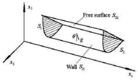
Fig.1 The sketch of open channel flow
1. Improved mechanical energy equation for steady channel flow
We consider the steady channel flow of a control volumeas shown in Fig.1, with the outer boundariescomposed of two cross-sectionsandat its upstream and downstream positions with a distancebetween them, the channel walland the free surface. For the statistically steady turbulent flow of homogeneous incompressible liquid of densityin the gravitational field, the mean surface force, whereandare the mean pressure and the mean viscous shear stress respectively can be expressed by using the Reynolds averaged equation(Eq.(7) of this paper) as
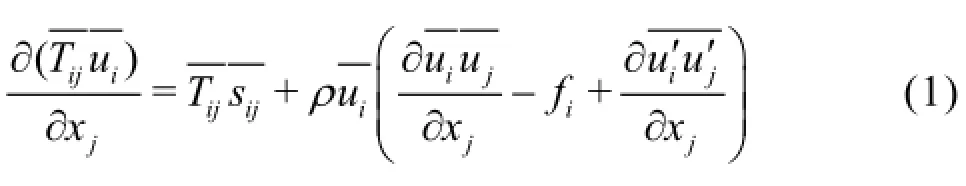
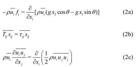
Therefore, Eq.(1) can be simplified further as
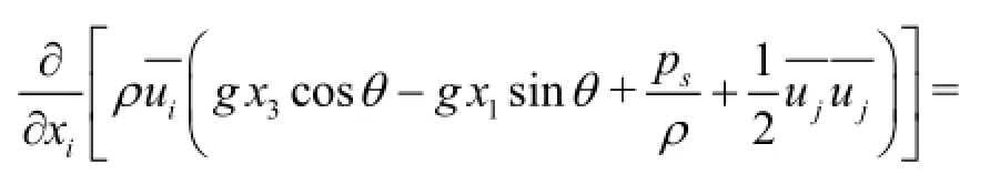
The boundary conditions for the steady channel flow are: on the channel wallthe mean velocity is zero, which is the so called no-slip condition, on the free surface, where, the kinematic boundary condition is, whereis the unit vector in the outward direction of the normal line on, the dynamical boundary conditions mean that there exist no shear stresses and the normal stress is just the atmospheric pressure. The above dynamical boundary conditions on the free surface are reasonable in the case that the relative velocity between the liquid and the air is not so large and the effect of the surface tension can be neglected.
Integrating Eq.(3) over the control volume, by transforming the volume integral into the surface integral using the Gaussian Theorem, we have
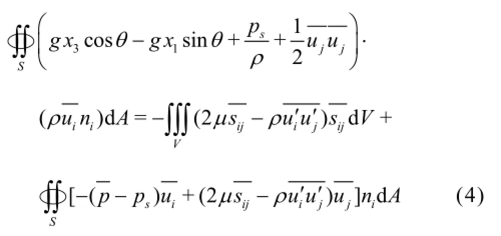
Now let us consider the integral terms in Eq.(4). Since for a static pressure field,is always equal to a constant on any cross-section, therefore by using the boundary conditions on the wall and on the free surface, as well as the continuity equation, we obtain
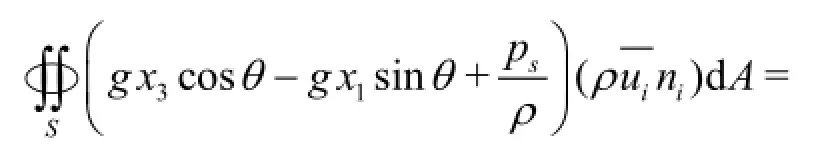
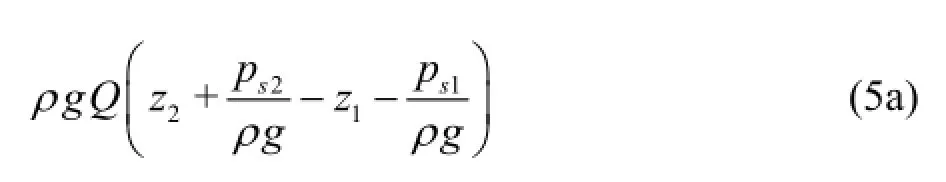
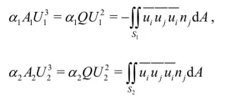
We have
Therefore if we further define
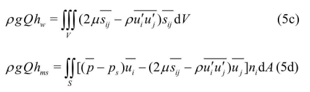
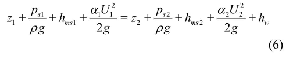
Equation (4) can be simplified as
2. Formulation of the momentum equation for steady channel flow
The Reynolds averaged equation for the steady channel flow is
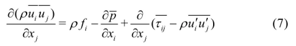
Integrating Eq.(7) over the control volume, transforming the volume integral into the surface integral using the Gaussian Theorem and projecting the integral result in the direction of, we have
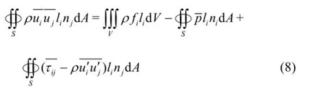
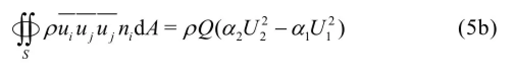
Euation (8) is the general form of the momentum equation for the total flow, and in this paper, only its longitudinal component (i.e., letandis discussed. By defining the angles between the outward directions of the normal line onandand the horizontal plane asand, and introducing the no-slip boundary condition on the channel wall and the kinematic boundary condition on the free surface,we have
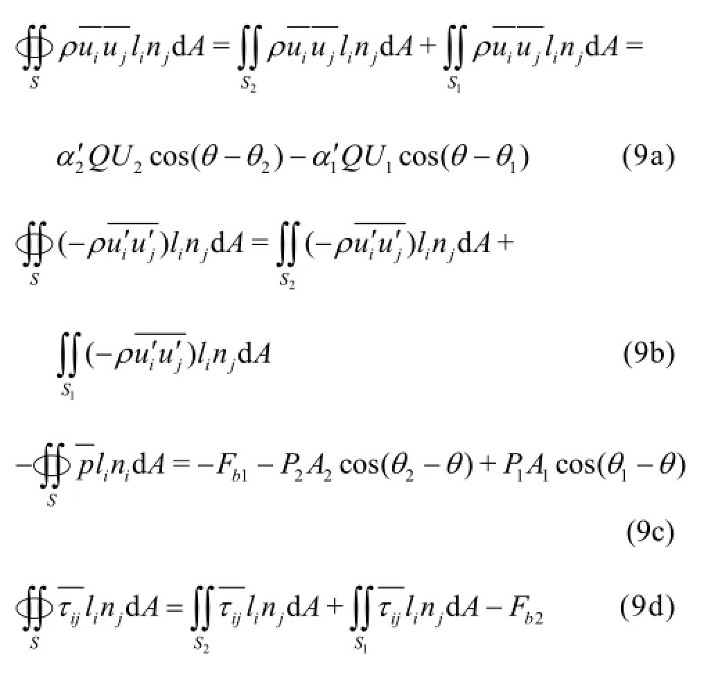
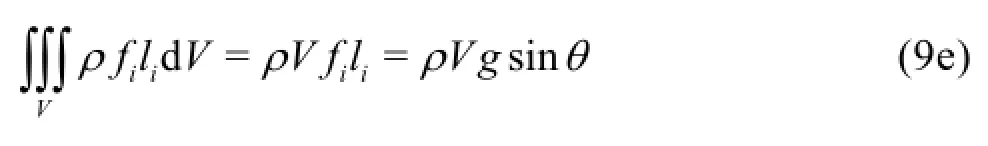
Substituting Eq.(9) into Eq.(8), we obtain the relationship between the total resistance on the channel walland the mechanical energy loss,as
The wall resistance and the mechanical energy loss are both the characteristics of the total flow in open channels, and there surely exists a certain relationship between them since the liquid flow is harmonious. This relationship is given in Eq.(10), where on the right hand side,are the resultant force of the mean pressure, the momentum variation, the resistance caused by the mechanical energy variation and the variation of the mean shear stress including the viscous shear stress and the Reynolds stress, respectively.
3. Wall resistance for steady uniform channel flow
If the shape of the cross section of the open channel does not change along the longitudinal direction and the channel is straight and long enough, the flow in it will be steady and uniform. In this case we have for Eq.(10):and, whereandare the wetted perimeter, the bed area and the wetted perimeter averaged shear stress, hereafter referred to as the mean shear stress, respectively. Under this condition, the mean shear stress of the steady uniform flow in open channels is simplified as
Substituting Eq.(5c) into Eq.(11), and defining the coefficient of the mechanical energy lossλas
Equation (13) expresses the relationship between the mean shear stress and the mean velocity in the section for the steady uniform channel flow. This formula is widely used in Hydraulics, which is deduced based ontheorem and dimensional analysis. However, in this paper, it is obtained directly from the governing equations of Fluid Mechanics. Defining the wall resistance coefficient for the steady uniform channel flow as, according to the definition we have
Comparing Eq.(13) with Eq.(14), we obtain that, i.e., the coefficient of the mechanical energy loss is three times larger than the wall resistance coefficient for the steady uniform channel flow.
4. Estimation of mechanical energy loss and wall resistance for steady backward-facing step flow
A sketch of the backward-facing step flow is shown in Fig.2, whereis the height of the stepis the water depth of the downstream uniform flow, and the expansion ratiois used to represent the step change. In view of the scope, only the 2-D backward-facing step flow with expansion ratio less than 5% is considered. Under this condition, the free surface would not be influenced by the step.
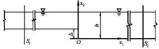
Fig.2 Sketch of the backward-facing step flow
4.1 Mathematical model and numerical calculation method
The governing equations for the mean velocityand the mean pressureare as follows:
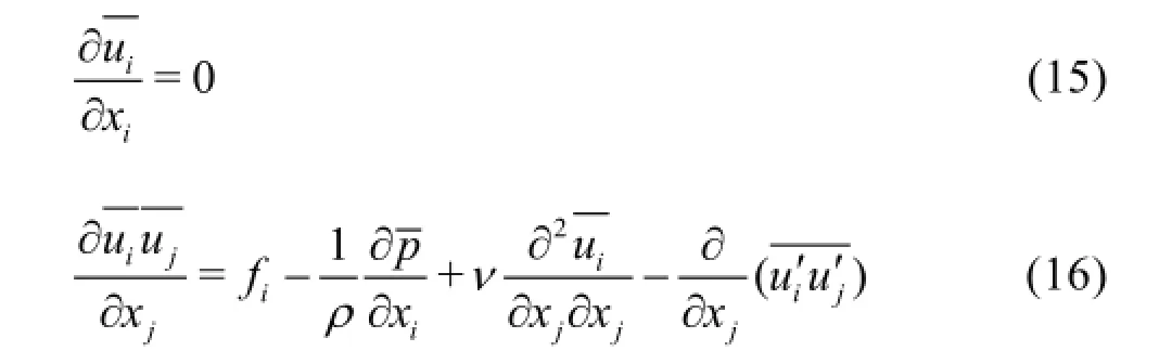
The governing equations are discretized by the finite volume method (FVM). The coupling relationship between the mean pressure and the mean velocity is handled with the SIMPLE scheme based on the collocated variable arrangement. A third-order accuracy QUICK scheme is used for the convection term while the central difference scheme is used for the diffusion term. The algebraic equations are solved by the Gauss-Seidel iteration method in this paper.
4.2 Verification
The experimental results[18]are used for verification. The experiment was conducted in a wind tunnel. A flat plate is put into the wind tunnel as shown in Fig.3. The velocity over the flat plate is measured with the pulsed-wire anemometer, which is used to verify the numerical model. The computed results are well consistent with the measured ones as shown in Fig.4,which shows that the calculated results from the numerical model can be further used to estimate the mechanical energy loss and other quantities.
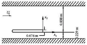
Fig.3 The experimental facility[18]
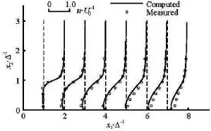
Fig.4 The verification results of the velocity distribution
4.3 Estimation of mechanical energy loss and wall resistance
4.3.1 Simulation conditions
In the simulation, the calculation cases are asfollows. The flow Reynolds numbervaries between 4×10⁴and 9×10⁴, and the expansion ratiovaries between 0.02 and 0.05. Under these conditions, the Froude numbers of all cases are less than 1, which shows that the flow is the subcritical flow in all calculation cases. The cross sectionis in the upstream of the step with a distance of 200-500 times of the step height while the cross section 2 S is in the downstream of the step with a distance of 200-500 times of the step height in order to make sure that the flow in these two sections is uniform.
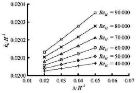
Fig.5 Variation of the mechanical energy loss with the Reynolds numbers and the expansion ratios
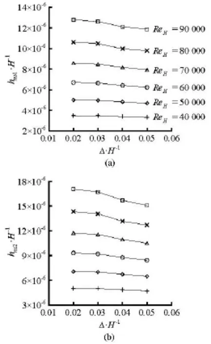
Fig.6 Variations of the surface force potential energy deviation between static liquid and moving liquid with the Reynolds numbers and the expansion ratios
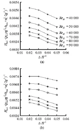
Fig.7 Variations of portion of surface force potential energy deviation in the mechanical energy excluding the gravitational potential energy
4.3.2 Mechanical energy loss and surface force potential energy deviation of total flow
4.3.3 Wall resistance
The wall resistance between the cross sectionsandincludes the form resistance and the viscous resistance, calculated from the simulation results, and the variations of the resistance forces against the Reynolds numbers and the expansion ratios are shown in Fig.8. As can be seen from Fig.8 that: (1) the viscous resistance is much smaller than the form resistance under given conditions, (2) the viscous resistance increases with the increase of the Reynolds number and decreases with the increase of the expansion ratio,(3) the form resistance decreases with the increase of the Reynolds number, and increases with the increase of the expansion ratio.
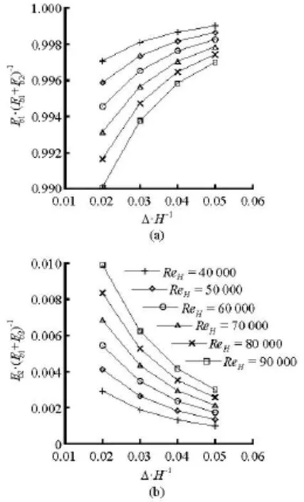
Fig.8 Variations of resistance forces with the Reynolds numbers and the expansion ratios
4.3.4 The relationship between wall resistance and mechanical energy loss of total flow Equation (10) shows that the wall resistance of the total flow between the cross sectionsandis approximately proportional to the mechanical energy loss. By converting Eq.(10) to its dimensionless form,we have
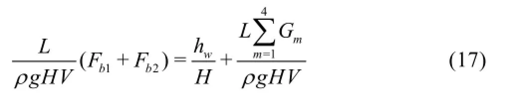
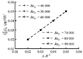
Fig.9 Variation ofagainst the Reynolds numbers and the expansion ratios
5. Conclusions
The mechanical energy loss and the wall resistance are investigated through theoretical analysis and numerical simulation in this paper. The following conclusions are drawn for the steady flow in open channels.
(1) A new mechanical energy equation for the total flow is obtained by defining the mechanical energy as the sum of the potential energy of gravity,the potential energy of surface force and the mean kinetic energy as in Hydraulics. The formula for the mechanical energy loss of the total flow is derived exactly while in Hydraulics it is determined empirically or experimentally.
(2) The general relationship between the wall resistance and the mechanical energy loss for steady channel flows is obtained by theoretical analysis, the simplified form of which for the steady uniform channel flow is in consistent with the formula used in Hydraulics deduced bytheorem and dimensional analysis.
(3) The steady channel flow over a backward facing step with a small expansion ratio is numerically simulated, and the mechanical energy loss, the wall resistance as well as the relationship between the wall resistance and the mechanical energy loss are calculated and analyzed based on the simulation results.
References
[1] KNIGHT D. W., STERLING M. Boundary shear in circular pipes running partially full[J]. Journal of Hydraulic Engineering, ASCE, 2000, 126(4): 263-275.
[2] CHEN Xiao-fang, HE Jian-jing. Experimental study on bed shear stress in smooth open channels[J]. Journal of Hohai University (Natural Sciences), 2007, 35(6): 704-708(in Chinese).
[3] CACQUERAY N. D., HARGREAVES D. M. and MORVAN H. P. A computational study of shear stress in smooth rectangular channels[J]. Journal of Hydraulic Research, 2009, 47(1): 50-57.
[4] KNIGHT D. W., OMRAN M. and TANG X. Modeling depth-averaged velocity and boundary shear in trapezoidal channels with secondary flows[J]. Journal of Hydraulic Engineering, ASCE, 2007, 133(1): 39-47.
[5] CHENG N. S. Resistance coefficients for artificial and natural coarse-bed channels: alternative approach for large-scale roughness[J]. Journal of Hydraulic Engineering, ASCE, 2015, 141(2): 04014072.
[6] HU Xu-yue, ZENG Guang-ming and HUANG Guo-he et al. Study on the boundary shear stress in rectangular open channels[J]. Journal of Sediment Research, 2002, (4): 42-47(in Chinese).
[7] YOON J., SUNG J. and LEE M. H. Velocity profiles and friction coefficients in circular open channels[J]. Journal of Hydraulic Research, 2012, 50(3): 304-311.
[8] PATNAIK M., PATRA K. C. and KHATUA K. K. et al. Modelling boundary shear stress in highly sinuous meandering channels[J]. ISH Journal of Hydraulic Engineering, 2014, 20(2): 161-168.
[9] BERLAMONT J. E., TROUW K. and LUYCKX G. Shear stress distribution in partially filled pipes[J]. Journal of Hydraulic Engineering, ASCE, 2003, 129(9): 697-705.
[10] ANSARI K., MORVAN H. P. and HARGREAVES D. M. Numerical investigation into secondary currents and wall shear in trapezoidal channels[J]. Journal of Hydraulic Engineering, ASCE, 2011, 137(4): 432-440.
[11] STOESSER T., RUETHER N. and OLSEN N. R. B. Calculation of primary and secondary flow and boundary shear stresses in a meandering channel[J]. Advances in Water Resources, 2010, 33(2): 158-170.
[12] GUO J., JULIEN P. Y. Shear stress in smooth rectangular open-channel flows[J]. Journal of Hydraulic Engineering, ASCE, 2005, 131(1): 30-37.
[13] YANG S. Q., LIM S. Y. Discussion of “Shear stress in smooth rectangular open-channel flows” by Junke Guo and Pierre Y. Julien[J]. Journal of Hydraulic Engineering, ASCE, 2006, 132(6): 629-632.
[14] KHODASHENAS S. R., ABDERERRZAK K. E. K. and PAQUIER A. Boundary shear stress in open channel flow: A comparison among six methods[J]. Journal of Hydraulic Research, 2008, 46(5): 598-609.
[15] LIU Shi-he, XUE Jiao and FAN Min. The calculation of mechanical energy loss for incompressible steady pipe flow of homogeneous fluid[J]. Journal of Hydridynamics, 2013, 25(6): 912-918.
[16] LIU Shi-he, FAN Min and XUE Jiao. The mechanical energy equation for total flow in open channels[J]. Journal of Hydridynamics, 2014, 26(3): 416-423.
[17] LIU Shi-he, LIU Jiang and LUO Qiu-shi et al. Engineering turbulence[M]. Beijing, China: Science Press,2011(in Chinese).
[18] DURST F., LAUNDER B. C. and SCHMIDT F. W. Turbulent shear flows I[M]. Berlin, Heidelberg, Germany: Springer-Verlag, 1979, 198-207.
April 16, 2015, Revised March 8, 2016)
* Biography: Shi-he LIU (1962-), Male, Ph. D., Professor
杂志排行

水动力学研究与进展 B辑的其它文章
- Scattering of gravity waves by a porous rectangular barrier on a seabed*
- Numerical simulations of viscous flow around the obliquely towed KVLCC2M model in deep and shallow water*
- A simple method for estimating bed shear stress in smooth and vegetated compound channels*
- A robust WENO scheme for nonlinear waves in a moving reference frame*
- Oscillating-grid turbulence at large strokes: Revisiting the equation of Hopfinger and Toly*
- A joint computational-experimental study of intracranial aneurysms: Importance of the aspect ratio*