Fabrication of micro-scale gratings for moiré method with a femtosecond laserGaosheng Yana,Jianguo Zhua,∗,Yanlong Huanga,Wenfen Haoa,Yanjie Lib
2016-09-21FcultyofCivilEngineeringndMechnicsJingsuUniversityZhenjing212013ChinSchoolofCivilEngineeringndArchitectureUniversityofJinnJinn250022Chin
Fculty of Civil Engineering nd Mechnics,Jingsu University,Zhenjing 212013,ChinSchool of Civil Engineering nd Architecture,University of Jinn,Jinn 250022,Chin
Letter
Fabrication of micro-scale gratings for moiré method with a femtosecond laser
Gaosheng Yana,Jianguo Zhua,∗,Yanlong Huanga,Wenfen Haoa,Yanjie Lib
aFaculty of Civil Engineering and Mechanics,Jiangsu University,Zhenjiang 212013,China
bSchool of Civil Engineering and Architecture,University of Jinan,Jinan 250022,China
H I G H L I G H T S
·We fabricate 500 lines/mm parallel gratings using a femtosecond laser.
·We theoretically optimize the grating profile to form high quality moiré patterns.
·Clear scanning electron microscope(SEM)moiré fringes are observed which is suitable for deformation measurement.
A R T I C L EI N F O
Article history:
in revised form
27 May 2016
Accepted 13 June 2016
Available online 22 June 2016
Micro-scale grating
Fabrication of micro gratings using a femtosecond laser exposure system is experimentally investigated fortheelectronmoirémethod.Microholesandlinesarefirstlyetchedforparameterstudy.Gratingprofile is theoretically optimized to form high quality moiré patterns.For a demonstration,a parallel grating is fabricated on a specimen of quartz glass.The minimum line width and the distance between two adjacent lines are both set to be 1µm,and the frequency of grating is 500 lines/mm.The experimental results indicate that the quality of gratings is good and the relative error of the gratings pitch is about 1.5%.Based on moiré method,scanning electron microscope(SEM)moiré patterns are observed clearly, which manifests that gratings fabricated with the femtosecond laser exposure is suitable for micro scale deformation measurement.
©2016 The Author(s).Published by Elsevier Ltd on behalf of The Chinese Society of Theoretical and
Applied Mechanics.This is an open access article under the CC BY-NC-ND license(http://
creativecommons.org/licenses/by-nc-nd/4.0/).
Deformation measurement and analysis under load is a key issuewhenthemechanicalpropertiesofmaterialsandstructuresare considered.Withthedevelopmentofscienceandtechnology,measurement methods for multiscale deformation from macroscale to micro-/nanoscale have drawn great attention.As a basic optical component,gratings can be used in various optical technologies,such as moiré interferometry[1],geometric phase analysis(GPA)[2],and various microscopic moiré methods[3],to measure the surface deformation on an object.As a conventional grating fabrication method developed in the early 1960s[4],holography lithography technique(HLT)is based on the interference of two coherentbeamsoflightandtheexposureofaphotoresist.Theprocess of HLT is relatively complex and includes coating the photoresist,exposure,development,and metal film deposition.In recent years,researchers have investigated a number of microscale fabrication technologies to fabricate gratings,such as X-ray lithography[5],electron beam lithography(EBL)[6],and focused ion beam milling[7].Although high-resolution alignment can be realized with these technologies,they are time consuming and of low throughput.In the mid-1990s,nanoimprint lithography(NIL)was initially proposed and developed by Chou’s group.It can create micro-and nanoscale patterns with submicron alignment over a large area.
As a major achievement of science and technology in 20th century,lasers have been widely used for microscale processing owing to a very high instantaneous power and small heat-affected zone.Recently they have been used to fabricate microstructures directlyonthesurfaceofmaterialssuchasmetals,semiconductors, and ceramics[8].Moreover,femtosecond laser can fabricate micro-gratings on the surface of the specimen without a mask, which provides an alternative method for grating fabrication, and its related research is of significant importance.Recently, femtosecond lasers were reported to fabricate microscale periodic structures.For example,Cheng fabricated micro-scale lines using femtosecond laser in indium tin oxide[9].Tan fabricated gratings by femtosecond laser interferometry method[10].Kishimoto proposed the fabrication of micromodel grids on the surfaceof polished steel specimens for various moiré methods by femtosecond laser exposure[11,12].With recent development of science and technology,the performance of femtosecond lasers has been improved,including spatial resolution and high peak intensity.Therefore,there remains a further study on highfrequency gratings fabricated using a femtosecond laser for deformation measurement with moiré method.
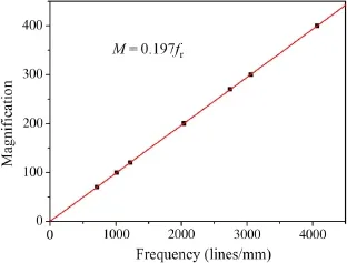
Fig.1.Calibration of frequency of reference grating with magnification(N=480).
In order to measure deformation in micro scale,moiré method are usually combined with a scanning electron microscope(SEM). The scanning lines in the SEM system can be regarded as a periodical grid and play the role of a reference grating.The SEM scanning moiré is generated by the superposition of the specimen grating and the scanning lines.The frequency of the reference grating,fr,is expressed as[13]

where M represents magnification,N is the number of scanning lines,and L0represents the gauge length of the SEM monitor perpendicular to the scanning lines.It can be seen that the frequencyofthescanninglinesisproportionaltothemagnification and the number of scanning lines while inversely proportional to the view field.
When the specimen grating is identical to the reference grating, moiré fringes will turn out,and the specimen grating will deform with the specimen if a load is applied.Generally,displacements and strains can be measured more accurately with gratings of higherfrequency.Therefore,fabricationofhigh-frequencygratings is of great importance[14].The frequency of the specimen grating is constant after fabrication while the frequency of the reference grating varies with the magnification.For the convenience of experiment with a JSM-7001F SEM,the frequency of reference grating has been calibrated as shown in Fig.1.The available number of scanning lines is 480.The size of each view field under different magnifications was measured and the corresponding frequencies were calculated.By fitting the relationship of the frequency of the reference grating with the magnification,the matched magnification M0to form null field moiré can be derived according to the frequency of the specimen grating.
The substrate was a quartz glass.The specimen was machined andpolished,andthenthemicroholesandlineswerefabricatedby laserexposureofthefemtosecondlasersystem(PharosFemtoLAB)withhighmagnificationlensandhighlyaccurateX-Y stage.During theexposureofthefemtosecondlaseronthesurface,theX-Y stage moved with positioning accuracy of 1µm.The exposure condition is shown in Table 1.
Micro holes with diameters from 1µm to 8µm were firstly fabricated as shown in Fig.2.The micro holes are very fine circles.

Table 1 Exposure condition of femtosecond laser.

Table 2 Processing parameters and measured depth of micro holes with the multi-pulse femtosecond laser.
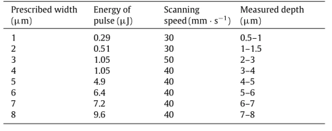
Table 3 Processing parameters and measured depth of micro lines with the multi-pulse femtosecond laser.
These fine holes were considered to be fabricated by femtosecond laser ablation.When the diameter is less than 4µm,the affected zone around the hole can hardly be observed,since the energy of laserpulseislessthan1µJ,asshowninTable2.Whenthediameter is larger than 4µm,the affected zone around the hole is obvious and it increases with the raised energy of pulse.Also the measured depth of the hole increases when the energy of pulse goes up.
Micro lines were fabricated by scanning the laser pulse with speed of 30-50 mm/s,as shown in Fig.3.The micro lines are very finestraightlineswithalmostequalwidthalongtheline.Whenthe diameter is less than 4µm and the maximum energy of laser pulse is 1.05µJ,the affected zone along the line can hardly be observed, whichisthesameasfabricationofmicroholes,asshowninTable3. Whenthediameterislargerthan4µm,theaffectedzonealongthe line is obvious and it also increases with the raised energy of pulse. The measured depth of the line increases when the energy of pulse goes up.
Parallel gratings were fabricated based on studying the above parameters.When parallel gratings are fabricated using a femtosecond laser,the frequency f and pitch p of the gratings can be expressed as

where d is the distance between two adjacent lines,and D represents the line width.Theoretically,the grating frequency is higher when D and d are smaller.
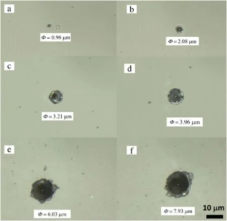
Fig.2.Optical images of micro holes fabricated with the femtosecond laser,and the measured diameter of the holes is(a)0.98µm,(b)2.08µm,(c)3.21µm,(d)3.96µm,(e)6.03µm,and(f)7.93µm.
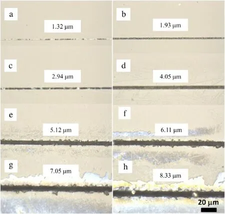
Fig.3.Optical images of micro lines fabricated with the femtosecond laser,and the prescribed width of the lines is 1-8µm from(a)-(h).
The fabrication of gratings with a femtosecond laser can be explained as shown in Fig.4.Assume that the horizontal dashed line is the threshold fluence for quartz glass ablation.The peak fluence of the laser beam is higher than the ablation threshold of quartz glass,and thus,the center area is ablated.The oblique line area of the laser pulse equals the ablated line width D,which changes with the energy of the laser pulse.However,the outer edges are subjected to lower irradiation intensity,and thus,a strip of quartz glass remained.According to the femtosecond laser system,the minimum line width and moving displacement of theX-Y stage are both 1µm.In order to fabricate high-frequency gratings,D was also set to be 1µm and d can be set less than 1µmwithablatedareasoverlapped,asshownontherightinFig.4. However,moirépatternshavethebestqualitywhenthelinewidth D equals to the distance between two adjacent lines d,or the duty ratio(D/d)equals to 1[15].Therefore,the magnitude of d was also set to be 1µm for the purpose of forming high quality moiré patterns.
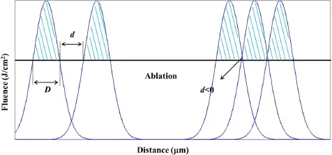
Fig.4.Schematic diagram of fabricating parallel gratings with a femtosecond laser.
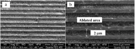
Fig.5.Parallel gratings fabricated by femtosecond laser exposure,(a)6000x and(b)12000x.
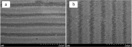
Fig.6.SEM moiré patterns:(a)parallel moiré and(b)rotational moiré.
Parallel gratings within area 3 mm×3 mm were fabricated with the femtosecond laser,as shown in Fig.5.As can be seen,the boundaryofeachlineisclear,andthecontrastbetweentheablated lines and original material is obvious.The average pitch is about 2µm and average frequency of the gratings is 500 lines/mm,and the relative error is about 1.5%.However,the measured duty ratio(D/d)is about 1.5,which is larger than the prescribed value.This is caused by the processing error of the femtosecond laser system, which can be reduced by carefully refining the experimental parameter of the specimen.
SEM moiré patterns were observed using the above parallel gratings(Fig.5).According to Fig.1,M0=98.5 to form a null field moiré with the frequency of specimen(fs)equals to 500 lines/mm. In practice,M was set to be 70-130,SEM moiré patterns were observed,as shown in Fig.6.Figure 6(a)and(b)show parallel moiré pattern and rotational moiré pattern,respectively.It can be seen that the moiré fringes are clear with dark and bright lines and the lines are equispaced and parallel with each other.The magnification is 90 and the frequency of scanning line(fr)is about 457 lines/mm,which is similar to the frequency of specimen.The strain of parallel moiré can be calculated as

where psand prare pitch of specimen gratings and scanning lines,respectively.Rotational moiré pattern can be formed by the superimposition of two similar patterns rotated by an angleφ.The relation of ps,pr,and the pitch of moiré(pm)is defined as[16,17]

whereφis the angle between the reference grating and the specimen grating.
In summary,the femtosecond laser exposure system was used to fabricate the micro gratings for the electron moiré method. Micro holes and lines were firstly experimentally investigated for parameter study.Grating profile was theoretically optimized to form high quality moiré patterns.For a demonstration,a parallel gratingwasfabricatedonaspecimenofquartzglass.Theminimum line width and the distance between two adjacent lines were both set to be 1µm,and the frequency of grating was 500 lines/mm. The experimental results indicate that the quality of gratings is good and the relative error of the average gratings pitch is about 1.5%.Based on moiré method,SEM moiré patterns were observedclearly,whichmanifeststhatgratingsfabricatedwiththe femtosecondlaserexposureissuitableformicroscaledeformation measurement.Furthermore,the gratings are suitable to be applied for the measurement of high temperature deformation since they are fabricated directly on the surface of specimen.
Acknowledgment
The authors are grateful for financial support from the National Natural Science Foundation of China(11372118 and 11302082).
[1]Y.Guo,W.T.Chen,C.K.Lin,Experimental deformation of thermal strains in semiconductor packaging using moiré interferometry,ASME,New York, 1992.
[2]Z.W.Liu,H.M.Xie,D.N.Fang,et al.,A novel nano-Moiré method with scanning tunneling microscope(STM),J.Mater.Process Technol 148(2004)77-82.
[3]J.L.Rouviere,E.Sarigiannidou,Theoretical discussions on the geometrical phase analysis,Ultramicroscopy 106(2005)1-17.
[4]E.H.Anderson,C.M.Horwitz,H.I.Smith,Holographic lithography with thick photoresist,Appl.Phys.Lett.43(1983)874-875.
[5]A.Ritucci,A.Reale,P.Zuppella,et al.,Interference lithography by a soft xray laser beam:Nanopatterning on photoresists,J.Appl.Phys.102(2007)034311-034314.
[6]H.M.Xie,S.Kishimoto,N.Shinya,Fabrication of high-frequency electron beam moiré grating using multi-deposited layer techniques,Opt.Laser Technol.32(2000)361-367.
[7]H.M.Xie,B.Li,R.Geer,et al.,Focused ion beam moiré method,Opt.Laser Eng. 40(2003)163-177.
[8]Y.C.Lee,C.M.Chen,C.Y.Wu,A new excimer laser micromachining method for axially symmetric 3D micro-structures with continuous surface profiles, Sensors Actuator A 117(2005)349-355.
[9]C.W Cheng,I.M.Lee,J.S.Chen,Femtosecond laser processing of indium-tinoxide thin films,Opt.Lasers Eng.69(2015)1-6.
[10]B.Tan,N.R.Sivakumar,K.Venkatakrishnan,Direct grating writing using femtosecond laser interference fringes formed at the focal point,J.Opt.A Pure Appl.Opt.7(2005)169-174.
[11]S.Kishimoto,Y.Tanaka,T.Tomimatsu,et al.,Fabrication of micromodel grid forvariousmoirémethodsbyfemtosecondlaserexposure,Opt.Lett.34(2009)112-114.
[12]Y.Tanaka,K.Naito,S.Kishimoto,et al.,Development of a pattern to measure multiscaledeformationandstraindistributionviainsituFE-SEMobservations, Nanotechnology 22(2011)115704.
[13]Y.J.Li,H.M.Xie,B.Q.Guo,et al.,Fabrication of high-frequency moiré gratings for microscopic deformation measurement using focused ion beam milling,J. Micromech.Microeng.20(2010)055037.
[14]Y.J.Li,H.M.Xie,Theoretical analysis of moiré fringe multiplication under scanning electron microscope,Meas.Sci.Technol.22(2011)025301.
[15]M.J.Tang,H.M.Xie,Q.H.Wang,et al.,Phase-shifting laser scanning confocal microscopy moiré method and its applications,Meas.Sci.Technol.21(2010)055110.
[16]Y.J.Li,H.M.Xie,P.Chen,et al.,Theoretical analysis of moiré fringe multiplication under a scanning electron microscope,Meas.Sci.Technol.22(2010)025301.
[17]F.L.Dai,G.L.Shen,H.M.Xie,Experimental Mechanics,Tsinghua University Press,Beijing,2010.
21 March 2016
.
E-mail address:zhujg@ujs.edu.cn(J.Zhu).
http://dx.doi.org/10.1016/j.taml.2016.06.001
2095-0349/©2016 The Author(s).Published by Elsevier Ltd on behalf of The Chinese Society of Theoretical and Applied Mechanics.This is an open access article under the CC BY-NC-ND license(http://creativecommons.org/licenses/by-nc-nd/4.0/).
Femtosecond laser
Moiré method
杂志排行
Theoretical & Applied Mechanics Letters的其它文章
- Editorial:Advances in Optical Techniques for Mechanical Measurements
- Residual stress measurement for injection molded componentsAchyut Adhikari∗,Thomas Bourgade,Anand Asundi
- Fabrication of nanoscale speckle using broad ion beam milling on polymers for deformation analysisQinghua Wanga,∗,Satoshi Kishimotob,Yoshihisa Tanakab,Kimiyoshi Naitob
- Instantaneous phase-stepping interferometry based on a pixelated micro-polarizer arraySatoru Yoneyama∗,Shuichi Arikawa
- Visualizing surface strain distribution of facial skin using stereovisionNagisa Miura,Tsubasa Sakamoto,Yuichi Aoyagi,Satoru Yoneyama∗
- The mechanics and deformation of high temperature steel frame rapidly cooled by spray water in fire fightingYunchun Xia
