Instantaneous phase-stepping interferometry based on a pixelated micro-polarizer arraySatoru Yoneyama∗,Shuichi Arikawa
2016-09-21DepartmentofMechanicalEngineeringAoyamaGakuinUniversity10FuchinobeSagamihara2525258Japan
Department of Mechanical Engineering,Aoyama Gakuin University,5-10-1 Fuchinobe,Sagamihara 252-5258,Japan
Letter
Instantaneous phase-stepping interferometry based on a pixelated micro-polarizer array
Satoru Yoneyama∗,Shuichi Arikawa
Department of Mechanical Engineering,Aoyama Gakuin University,5-10-1 Fuchinobe,Sagamihara 252-5258,Japan
H I G H L I G H T S
·A camera equipped with micro-polarizer array is used in a polarization interferometer. ·Phase values of interference fringes can be obtained from a single image.
·This method can be applied to the measurement of time-varying phenomena.
A R T I C L EI N F O
Article history:
in revised form
22 March 2016
Accepted 14 May 2016
Available online 2 June 2016
Instantaneous phase-stepping method
Mach-Zehnder interferometry
Micro-polarizer array
Polarization
Fringe
Crack
In this paper,we propose an instantaneous phase-stepping method for determining phase distribution of interference fringes utilizing a camera that is equipped with a micro-polarizer array on the sensor plane.An optical setup of polarization interferometry using a Mach-Zehnder interferometer with two polarizers is constructed.Light emerging from the interferometer is recorded using a camera that has a micro-polarizerarray.Thismicro-polarizerarrayhasfourdifferentopticalaxes.Thatis,animageobtained by the camera contains four types of information corresponding to four different optical axes of the polarizer.The four images separated from the image recorded by the camera are reconstructed using gray level interpolation.Subsequently,the distributions of the Stokes parameters that represent the state of polarization are calculated from the four images.The phase distribution of the interference fringe pattern produced by the Mach-Zehnder interferometer is then obtained from these Stokes parameters. The effectiveness of the proposed method is demonstrated by measuring a static carrier pattern and time-variant fringe patterns.It is emphasized that this method is applicable to time-variant phenomena because multiple exposures are unnecessary for sufficient data acquisition in the completion of the phase analysis.
©2016 The Author(s).Published by Elsevier Ltd on behalf of The Chinese Society of Theoretical and
Applied Mechanics.This is an open access article under the CC BY-NC-ND license(http://
creativecommons.org/licenses/by-nc-nd/4.0/).
Several interferometric techniques,such as moiré,Twyman-Green,Mach-Zehnder,holographic and speckle pattern interferometries,have long been used for studying mechanical deformation of solids and the mechanics of fracture[1-4].Several techniques exist for the analysis of fringe patterns obtained by these methods.Among them,phase-stepping(or phase-shifting)method is the most important and widely accepted techniques[5]. Phase-stepping interferometry is a simple and precise method for converting interferograms into phase maps.However,it is known that a temporal phase-stepping method has the disadvantage of a time lag during phase stepping and acquisition between phase steps.
Morimoto and co-workers[6-8]developed a high-speed temporal phase-shifting method for real-time measurement and applied it to analyses of time-varying Twyman-Green,moiré, and photoelastic fringes.Their method is applicable to slowly varying problems,but it is fundamentally difficult to analyze timevariant problems by their method because the multiple phasestepped images cannot be obtained simultaneously.Another approach to real-time measurement or instantaneous recording of phase-stepped images is a spatial phase-stepping method.The spatial phase-stepping method generates simultaneous phasestepped interferograms using polarization optics or diffraction grating[5].Several researchers have developed an instantaneous spatial phase-stepping method that uses multiple cameras for the acquisition of phase-stepped interferograms[9-13].Others have appliedittomeasurementsofcrystalgrowth[14]andsupercritical flow [15].The major drawback of this technique is the high complexity of the experimental setup,which requires perfect alignment and calibration of the pixels of multiple cameras.On the other hand,Novak et al.[16]proposed a method for recordingmultiple phase-stepped images using a camera with micropolarizers.Similarly,one author[17,18]proposed instantaneous phase-stepping interferometry and photoelasticity using a camera equippedwithamicro-retarderarray.Furthermore,thistechnique has been used for evaluating the stress fields around a propagating crack tip in a glass plate under thermal load[19].Recently,on the other hand,a high-speed camera that is equipped with a micro-polarizer array on the sensor plane is available[20-22]. Whereas this camera has been developed for the measurement of birefringence,it is considered that the instantaneous recording of phase-stepped interference fringes is possible using this camera, similar to the Novak’s method[16].
In this paper we propose an instantaneous phase-stepping method for determining phase distribution of interference fringes utilizing a camera equipped with a micro-polarizer array on the sensor plane.An optical setup of polarization interferometry using a Mach-Zehnder interferometer with two polarizers is constructed to analyze the distribution of the thickness change of thetransparentsample,i.e.,thesumofprincipalstressesinthecase of the plane stress state.Light emerging from the interferometer is recorded using a camera that has a micro-polarizer array on a sensor plane.This micro-polarizer array has four different optical axes.That is,an image obtained by the camera contains four types of information corresponding to four different optical axes of the polarizer.The four images separated from the image recorded by the camera are reconstructed using gray level interpolation. Subsequently,the distributions of the Stokes parameters that represent the state of polarization are obtained from the four images.The phase distribution of the interference fringe pattern produced by the Mach-Zehnder interferometer is then obtained from these Stokes parameters.
Figure 1 portrays the outline of the camera equipped with the micro-polarizer array on the sensor plane.As shown in this figure,many sets of four(2× 2)micro-polarizers whose optical axes subtend four different angles,0,π/4 rad,π/2 rad, 3π/4 rad,form the large array the sensor.The size of a single micro-polarizer is equivalent to a single pixel of the sensor. The micro-polarizer position is aligned with the sensor.A single sensor detects the intensity of a light that passes through a single polarizer with a specific angle of the optical axis.Then, the four light intensity distributions corresponding to the four optical axes are obtained as a single image.Spatial resolution of each light intensity distribution is reduced to one-fourth of the CCD’s resolution.In addition,the spatial positions of the four light intensitydistributionsdonotmutuallycorrespond.Therefore,light intensities other than the angle of the polarizer at the point are determined from light intensities at the neighboring points using interpolation such as bilinear or bicubic interpolation methods. Then,the four light intensity distributions whose respective sizes are equivalent to the original image are obtained by a single exposure.The four light intensity distributions are therefore phase-stepped images,similar to those obtained in other phasestepping methods.
The interferometer used in this study is shown in Fig.2.This interferometer consists of a Mach-Zehnder interferometer,two polarizers,and a quarter-wave plate.Light emitted from a point light source is collimated using a collimator lens.Then,a beam splitter divides the light.The light beam reflected by the beam splitter passes through a polarizer whose optical axis is vertical and a transparent specimen.Meanwhile,the light that passes through the beam splitter passes a polarizer whose optical axis is horizontal.In the case of an ordinary Mach-Zehnder interferometer,the two light beams interfere at the beam splitter.Then,the interference fringe pattern is observed.On the other hand,no interference fringe pattern is observed for the interferometer shown in Fig.2 because polarization directions of the two light beams cross at the rightangles.TheStokesvectorofthelightemergingfromthebeam
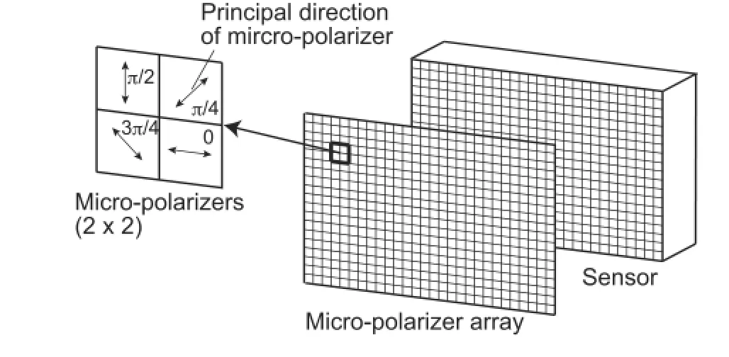
Fig.1.Configuration of the micro-polarizer array on the sensor plane.
splitter is expressed as follows

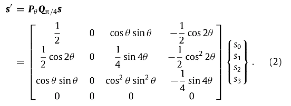
Therein,s0,s1,s2,and s3are the Stokes parameters,Axand Ayare the amplitude components,δrepresents the phase difference.The light beam passes through a quarter-wave plate and the polarizer attached on the sensor plane whose optical axis isθ.The Stokes vector of the light beam at the sensor plane is expressed as
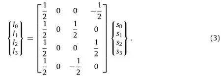
Therefore,the four light intensities,I0,I1,I2,and I3,corresponding to the four different angles of the polarizers,θ=0,π/4 rad, π/2 rad,3π/4 rad are obtained as
Then,the Stokes parameters s2and s3of the light emerging from the interferometer are obtainable as

Therefore,the phase value of the interference fringe is obtained as follows

Using the above interferometer and the camera,the wrapped phase map is obtainable from an image obtained by a single exposure.A phase unwrapping procedure can be introduced to obtain the unwrapped phase map.Then,the sum of principal stresses is obtained for plane stress specimen as[23]

whereσ1andσ2are the principal stresses,fsis the material constant,and d expresses the thickness of the specimens.It is notedthat this method can be applied to other interferometers than the Mach-Zehnder interferometer with the similar principle.
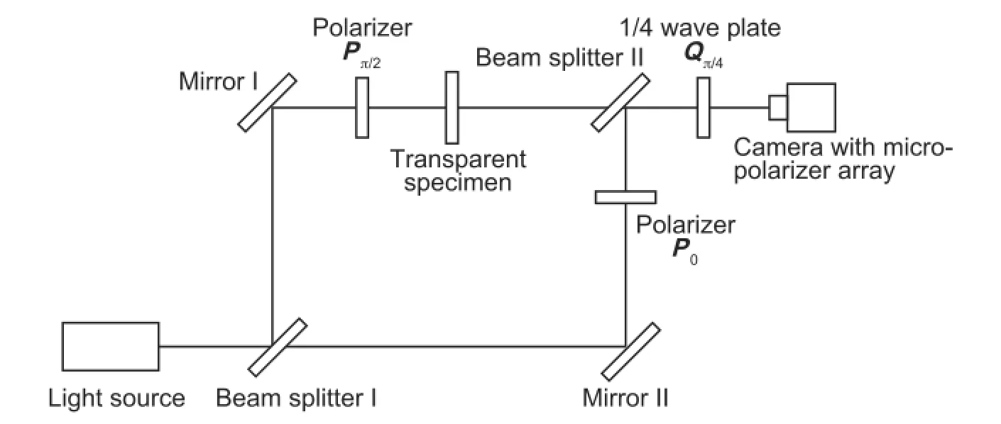
Fig.2.Optical setup of Mach-Zehnder interferometry with polarizers and quarter-wave plate.
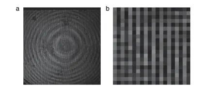
Fig.3.(a)Light intensity distribution obtained using the camera with the micro-polarizer array;(b)magnified image of 20×20 pixels region.
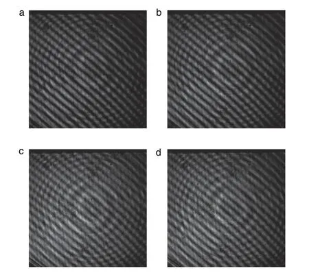
Fig.4.Separated images corresponding to optical axis of the polarizer:(a)θ=0;(b)θ=π/4;(c)θ=π/2;(d)θ=3π/4.
A carrier pattern analysis without a transparent specimen is performed to validate the proposed method.The optical system in Fig.2 without the specimen is adjusted to appear the carrier pattern.Then,thelightemergingfromtheinterferometerandthen the quarter-wave plate is acquired using a camera with the micropolarizer array(Photron FASTCAM SA5P)with the resolution of 1024×1024pixelsandthegraylevelsof8bits.Thelightsourceisa YAGlaserwiththewavelengthof532nm.Aquarter-waveplatefor the wavelength of 514.5 nm is used for the interferometer because a quarter-wave plate for 532 nm is not available in the present stage.
Figure 3(a)shows the image obtained by the camera with the micro-polarizer array;Fig.3(b)shows a magnified image of the 20×20pixelsregion oftheimageinFig.3(a).AsshowninFig.3(b), the gray level shows an unnatural and grating-like distribution causedbythemicro-polarizerarrayonthesensorplane.Theimage in Fig.3(a)is separable into four images corresponding to the four micro-polarizers,as shown in Fig.4.An interference fringe pattern cannot be observed in the case of the interferometer shown in Fig.2.In Fig.4,however,the phase-stepped interference fringes are observed because of the presence of the polarizer on the sensor plane.Theseseparatedimagescanbeconsideredasphase-stepped images.The phase map of the carrier pattern obtained by the proposed method is shown in Fig.5.It is noted that no smoothing process is introduced to the image in this figure.As shown in this figure,the phase map of the equally spaced carrier pattern is obtained by the proposed procedure.Figure 6 shows the phase distribution along a line around the center of the phase map in Fig.5.In this figure,the straight line expresses the approximation obtained using the least-squares.Because the values in Fig.6 represent the phase of the carrier pattern,the distribution can be approximated by a straight line.However,the curved distribution isobservedinthephaseinFig.6.Themaximumdifferencebetween the phase value and the approximated straight line is estimated as 0.75 rad,the average is 0.23 rad,and the standard deviation is 0.17 rad.There are some error sources such as the unmatched wavelength of the quarter-wave plate.On the other hand,the effectiveness of the proposed method is verified.That is,the phase analysis is possible from an image obtained using the camera with the micro-polarizer array.
Next,the phase analyses of the time-variant interference fringes are performed.The outline of the specimen and the loadingdeviceisschematicallyshowninFig.7.Atransparentspecimen made of polymethylmethactylate(PMMA)is used.The modulus of elasticity E and the Poisson’s ratioνof the material are measured as E=3.0 GPa andν=0.3,respectively.The adopted specimen is a strip plate with 80 mm in width,20 mm in height,and 3 mm in thickness,having a notch of the 2 mm in length.The notch is introducedbyarazor.Thespecimenisplacedonafour-pointbending device.Then,a weight is dropped onto the upper loading device.The specimen is subjected to the impact load by the dropped weight.The time-variant interference fringes around the notch are then recorded by the camera with the micro-polarizer array at the frame rate of 150,000 fps.The image size is set to 128×240 pixels.
Figure8showstheconsecutivephasemapsofthe Mach-Zehnder fringes obtained by the proposed method.These phasemapsareobtainedbysubtractingthephaseatthestaticstate before the load from the phase after the load.That is,the phase maps in Fig.8 represent the phase difference between the images before and after the load.It is observed that the number of the interference fringes increase with time and the fringes concentrate at the notch tip.It is noteworthy that,as shown in this figure,the phase values of the time-variant interference fringes are obtainable using the instantaneous phase-stepping method based on the micro-polarizer array.
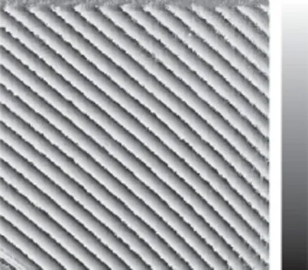
Fig.5.Phase map of the carrier pattern obtained by the proposed phase-stepping method.
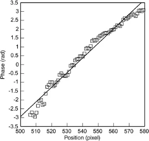
Fig.6.Phase distribution of the carrier pattern along a line.
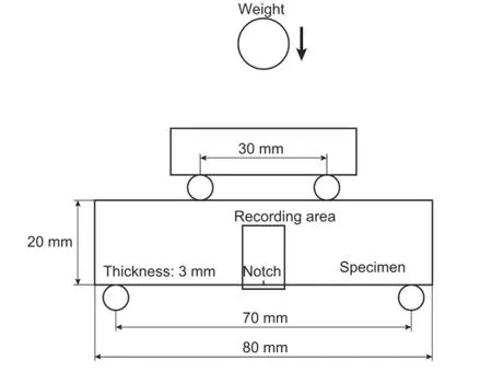
Fig.7.Specimen and loading configuration for dynamic test.
It is observed that the crack starts to propagate after increasing the phase values,that is,the sum of the principal stresses near the notch tip.Figure 9 shows an example of the phase distribution during the crack propagation.At the instant of crack propagation in Fig.9,the crack propagates at the speed of about 579 m·s-1. As shown in this figure,a reasonable phase distribution cannot be obtained for the propagating crack because the speed of the change of the phase distributions is too fast to record the camera employed in this experiment.As shown in Fig.8,however,the timevariationoftheinterferencefringesforthephenomenawhosespeed of change is suited for the camera speed can be analyzed by the proposed instantaneous phase-stepping interferometry.

Fig.8.Series of 6 consecutive phase maps of Mach-Zehnder fringes around a notch:camera speed 150,000 frames per sec.
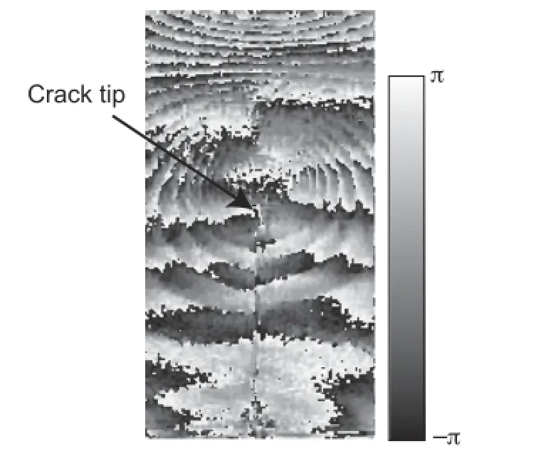
Fig.9.Phase map obtained during crack propagation.
In this paper we propose an instantaneous phase-stepping method for determining phase distribution of interference fringes utilizing a camera equipped with a micro-polarizer array on the sensor plane.Light emerging from the interferometer is recorded using a camera that has a micro-polarizer array on a sensor plane.An image obtained by the camera contains four types of information corresponding to four different optical axes of the micro-polarizer.Subsequently,the distributions of the Stokes parameters that represent the state of polarization are evaluated from the four images.The phase distribution of the interference fringe pattern produced by the Mach-Zehnder interferometer is then obtained from these Stokes parameters.It is emphasized that this method is applicable to time-variant phenomena because multiple exposures are unnecessary for sufficient data acquisition in the completion of the phase analysis.
Acknowledgments
The authors express their thanks to Messrs.A.Mihara,T.Sasaki, and T.Onuma of Photron Limited for kindly providing the highspeedcameraequippedwiththemicro-polarizerarray.Ourthanks are extended to Mr.Y.Furuichi for his help in the experiments.
[1]B.Han,Thermal stresses in microelectronics subassemblies:quantitative characterization using photomechanics methods,J.Therm.Stresses 26(2003)583-613.
[2]X.L.Gong,S.Toyooka,Investigation on mechanism of plastic deformation by digital speckle pattern interferometry,Exp.Mech.39(1999)25-29.
[3]R.D.Pfaff,P.D.Washabaugh,W.G.Knauss,An interpretation of twyman-green interferograms from static and dynamic fracture experiments,Int.J.Solids Struct.32(1995)939-955.
[4]S.Yoneyama,H.Kamihoriuchi,A method for evaluating full-field stress components from a single image in interferometric photoelasticity,Meas.Sci. Technol.20(2009)075302.
[5]J.M.Huntley,Automated fringe pattern analysis in experimental mechanics:a review,J.Strain Anal.Eng.Des.33(1997)105-125.
[6]M.Fujigaki,Y.Morimoto,M.Yabe,Real-time measurement of nanometer displacement distribution by integrated phase-shifting method,JSME Int.J., Ser.A 45(2002)448-452.
[7]Y.Yamamoto,Y.Morimoto,M.Fujigaki,Two-directional phase-shifting moiré interferometry and its application to thermal deformation measurement of an electronic device,Meas.Sci.Technol.18(2007)561-566.
[8]S.Yoneyama,Y.Morimoto,R.Matsui,Photoelastic fringe pattern analsysi by real-time phase-shifting method,Opt.Lasers Eng.39(2003)1-13.
[9]R.Smythe,R.Moore,Instantaneousphasemeasuringinterferometry,Opt.Eng. 23(1984)361-364.
[10]C.L.Koliopoulos,Simultaneous phase shift interferometer,Proc.SPIE 1531(1991)119-127.
[11]A.J.P.van Haasteren,H.J.Frankena,Real-time displacement measurement using a multicamera phase-stepping speckle interferometer,Appl.Opt.33(1994)4137-4142.
[12]B.K.A.Ngoi,K.Venkatakrishnan,N.R.Sivakumar,et al.,Instantaneous phase shifting arrangement for microsurface profiling of flat surfaces,Opt.Commun. 190(2001)109-116.
[13]N.R.Sivakumar,W.Hui,K.Venkatakrishnan,et al.,Large surface profile measurement with instantaneous phase-shifting interferometry,Opt.Eng.42(2003)367-372.
[14]K.Onuma,T.Nakamura,S.Kuwashima,Development of new real-time phaseshift interferometry for the investigation of crystal growth kinetics,J.Cryst. Growth 167(1996)387-390.
[15]E.Astrakharchik-Farrimond,B.Y.Shekunov,P.York,et al.,Dynamic measurements in supercritical flow using instantaneous phase-shift interferometry, Exp.Fluids 33(2002)307-314.
[16]M.Novak,J.Millerd,N.Brock,et al.,Analysis of a micropolarizer array-based simultaneous phase-shifting interferometer,Appl.Opt.44(2005)6861-6868.
[17]S.Yoneyama,H.Kikuta,K.Moriwaki,Instantaneous phase-stepping interferometry using polarization imaging with a micro-retarder array,Exp.Mech.45(2005)451-456.
[18]S.Yoneyama,H.Kikuta,K.Moriwaki,Simultaneous observation of phasestepped photoelastic fringes using a pixelated microretarder array,Opt.Eng. 45(2006)083604.
[19]S.Yoneyama,K.Sakaue,H.Kikuta,et al.,Observation of stress field around an oscillating crack tip in a quenched thin glass plate,Exp.Mech.48(2008)367-374.
[20]W.Murata,E.Umezaki,T.Onuma,et al.,Phase-shifting photoelasticity using polarization high-speed camera,in:5th International Symposium on Advanced Science and Technology in Experimental Mechanics,Kyoto, November 2010.
[21]T.Onuma,Y.Otani,Real-time measurement method for birefringence distribution by dynamic stokes polarimeter,in:International Symposium on Optomechatronic Technologies,Hong Kong,November 2012.
[22]T.Kakue,R.Yonesaka,T.Tahara,et al.,High-speed phase imaging by parallel phase-shifting digital holography,Opt.Lett.36(2011)4131-4133.
[23]S.Yoneyama,S.Arikawa,T.Shibayama,Stress separation of interferometrically measured isopachics in a perforated plate,Exp.Mech.52(2012)659-667.
12 November 2015
.
E-mail address:yoneyama@me.aoyama.ac.jp(S.Yoneyama).
http://dx.doi.org/10.1016/j.taml.2016.05.004
2095-0349/©2016 The Author(s).Published by Elsevier Ltd on behalf of The Chinese Society of Theoretical and Applied Mechanics.This is an open access article under the CC BY-NC-ND license(http://creativecommons.org/licenses/by-nc-nd/4.0/).
杂志排行
Theoretical & Applied Mechanics Letters的其它文章
- Editorial:Advances in Optical Techniques for Mechanical Measurements
- Residual stress measurement for injection molded componentsAchyut Adhikari∗,Thomas Bourgade,Anand Asundi
- Fabrication of nanoscale speckle using broad ion beam milling on polymers for deformation analysisQinghua Wanga,∗,Satoshi Kishimotob,Yoshihisa Tanakab,Kimiyoshi Naitob
- Visualizing surface strain distribution of facial skin using stereovisionNagisa Miura,Tsubasa Sakamoto,Yuichi Aoyagi,Satoru Yoneyama∗
- Fabrication of micro-scale gratings for moiré method with a femtosecond laserGaosheng Yana,Jianguo Zhua,∗,Yanlong Huanga,Wenfen Haoa,Yanjie Lib
- The mechanics and deformation of high temperature steel frame rapidly cooled by spray water in fire fightingYunchun Xia
