Acoustic emission assessment of interface cracking in thermal barrier coatings
2016-09-06LiYangZhiChunZhongYiChunZhouWangZhuZhiBiaoZhangCanYingCaiChunShengLu
Li Yang·Zhi-Chun Zhong·Yi-Chun Zhou·Wang Zhu· Zhi-Biao Zhang·Can-Ying Cai·Chun-Sheng Lu
Acoustic emission assessment of interface cracking in thermal barrier coatings
Li Yang1,2·Zhi-Chun Zhong1,2·Yi-Chun Zhou1,2·Wang Zhu1,2· Zhi-Biao Zhang1,2·Can-Ying Cai1,2·Chun-Sheng Lu3
©The Chinese Society of Theoretical and Applied Mechanics;Institute of Mechanics,Chinese Academy of Sciences and Springer-Verlag Berlin Heidelberg 2015
AbstractIn this paper,acoustic emission(AE)and digital image correlation methods were applied to monitor interface cracking in thermal barrier coatings under compression.The interfacefailureprocesscanbeidentifie viaitsAEfeatures, including buckling,delamination incubation and spallation. According to the Fourier transformation of AE signals,there arefourdifferentfailuremodes:surfaceverticalcracks,opening and sliding interface cracks,and substrate deformation. The characteristic frequency of AE signals from surface vertical cracks is 0.21 MHz,whilst that of the two types of interface cracks are 0.43 and 0.29 MHz,respectively.The energy released of the two types of interface cracks are 0.43 and 0.29 MHz,respectively.Based on the energy released from cracking and the AE signals,a relationship is establishedbetweentheinterfacecracklengthandAEparameters, which is in good agreement with experimental results.
KeywordsThermal barrier coatings·Acoustic emission· Interface cracking·Crack type·Quantitative analysis
1 Introduction
Thermal barrier coatings(TBCs),as a key technique for improving the efficien y and performance of advanced gas turbines[1-4],are a multilayered system consisting of a thermally insulating ceramic coating with yttria-stabilized zirconia composition,a metallic bond coating that provides oxidation/corrosion protection,a Ni-based superalloy substrate,and a thermally grown oxide(TGO)layer that forms at the ceramic/bond coating interface during deposition and in service.Each layer has remarkably different physical, thermal,and mechanical properties.For example,thermal expansion coefficient of ceramic coating and TGO are considerably smaller than that of substrate,which results in compressive stress in ceramic coating and TGO during cooling.The misfi compressive stress in the latter is up to 3-6 GPa[1,3,5,6],which may trigger interface failure at the ceramic/bond coating interface.The integrity of this interfaceisofparamountimportancebecause,ifspallationoccurs, the local induced hotspots will accelerate degradation of the bond coating and superalloy[7-9].In practice,TBCs with complex geometries and interface structures usually work under harsh operating conditions,and thus the prediction of their service life is rather difficult Therefore,to elucidate failure mechanisms and assess their service reliability, it is desirable to monitor in real time the failure process of TBCs.
Acoustic emission(AE)is a natural phenomenon,where an external stimulus,such as mechanical or thermal loading,generates a source of elastic waves.When materials are subjected to deformation and damage such as crack nucleation and propagation,dislocation motion,and twin formation[10-16],the stored energies are released in transient elastic waves,namely AE signals that can bedetected by sensors.Based on the AE technique,the failure behavior of TBCs under various mechanical and thermal loadings has been qualitatively studied via the duration, count,energy,and amplitude of AE signals[10-17].It is instructive to the design of material compositions[16], the optimization of preparation parameters[15]and the influenc factor analysis on fracture[14,17,18].To apply the AE method to the real-time assessment of a fracture process in TBCs,the key problem is how to discriminate the type of cracks,and further to quantify them.Recent experiments have shown that the frequency spectra of AE signals are strongly dependent on the fracture types of materials[10-12,17-20].Based on the frequency analysis of AE signals,the coating damage in TBCs under tension commonly originates from vertical cracks and then follows delamination[17],but during static thermal cycling in a furnace,vertical cracks take priority under heating and interface cracks under cooling[10].It is worth noting, however,that the failure mode is complicated for complex structures such as TBC vanes or blades in harsh environments.
Based on the research on concretes[21],metallic,and ceramic coatings[22,23],there is a linear relationship between the AE and fracture energies.Similarly,a quantitative correlation was obtained between the surface vertical cracks of TBCs and their AE features[12].Surface vertical cracks in ceramic coating,activated by tensile stress due to thermal mismatch,sintering,and phase transformation, serve as a pathway of oxygen migration and thermal diffusion,and thus degrade the oxidation resistance and thermal insulation performance of coatings.When arriving to the interface,these surface cracks kink and result in the nucleation and propagation of interfacial cracks that lead to the ultimate spallation of ceramic coatings and the elimination of thermal insulation capability.Therefore,the quantitative assessment of interface cracks is essential to analyze a failureprocessofTBCs.Ithasbeenrevealedthatduringthermal loading,largeresidualstressesaredevelopedinceramiccoatings and TGO due to thermal mismatch.These compressive stresses usually result in buckling of coatings[1,10,17]. To track easily the location and path of interface cracking,here TBCs with a prefabricated crack are investigated under compression.Our focus is on the discrimination of interface cracks and their quantitative assessment by using the AE method.The paper is organized as follows.Section 2 is dedicated to experimental details.In Sect.3,the interface fracture process of TBCs is discussed,including various crack types and their failure mechanisms.Section 4 concentrates on the correlation between the interface crack length and AE energy.Finally,a brief summary is given in Sect.5.
2 Experimental
2.1Specimens with interface defects
The TBC specimens were made by a typical air plasma spraying method.First,a Ni-based superalloy GH3030 substrate was cut into 20×5×5 mm3pieces with an electrical dischargewirecuttingmachineandcleanedupwithanultrasonic cleaning machine.Then,NiCr22Al7Y0.2bond coating was deposited on the substrate.Based on our previous work [24],a region of low adhesion(i.e.,an artificia interface defect)is necessary at the TBC/bond coating interface to determine precisely the delamination buckling location and itspropagation path.Therefore,a nickel foil with a thickness of 40 μm was placed on the bond coating as a through-width interfacedefect.Finally,aZrO2−8wt%Y2O3ceramiccoating was deposited on the free surface of nickel foil and bond coating.As illustrated in Fig.1,the thicknesses of bond and ceramic coatings are 80 and 350 μm,respectively,and the length of an interface defect is 5 mm.

Fig.1 aSchematicdimensionsand bmicrostructureofspecimenwith an interface defect
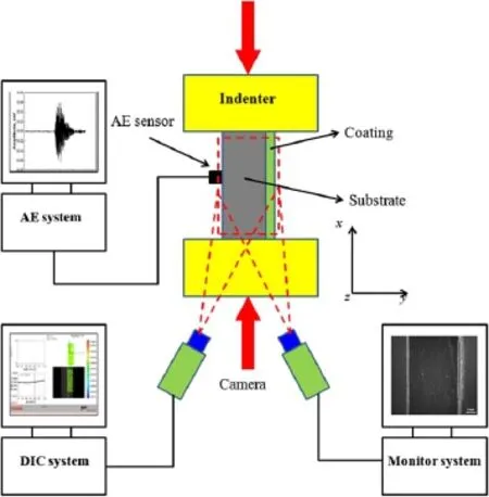
Fig.2 Illustration of AE and charge-coupled device camera monitoring apparatus in compression tests,where DIC indicates digital image correlation

Fig.3 Typical frequency spectra of four failure modes from compression of a TBC specimen
2.2AE and digital image correlation tests
As schematized in Fig.2,compressive tests were carried out on an RG2000 universal testing machine.All specimens were tested along the direction parallel to the film/substrat interface and with a loading rate of 250 N/min.A PCI-II AE system was used to monitor the AE signals that were detected by the NANO30 sensor placed on the surface of the substrate with a resonance of 70-400 kHz.The threshold,pre-amplifie,and sampling rate were set as 38,40 dB, and 2 MHz,respectively.Prior to testing,two special black and white paintings,called speckle patterns,were sprayed on the polished coating of the specimen’s lateral sides with an airbrush.By tracking features on the specimen surface with these speckle patterns,a displacement fiel can be measuredwithadigitalimagecorrelationsystem(Aramis).Here, images were taken at a sampling rate of one frame per 2.5 s. With the help of the Aramis 3D software,the evolution of strain field can be extracted with a measuring accuracy of ~0.05%.In addition,a 2452×2056 pixels charge-coupled device camera(AVT-Manta G504)equipped with a lens of 50mmfocallengthwasplacedinfrontofthecross-sectionof aspecimen,andthesamplingratewasoneframepersecond.
3 Failure mechanism
Generally speaking,the characteristic frequencies of AE signals are dependent on the failure modes of TBCs[10-12,17,18].The characteristic frequency spectrum of AE signalswerecalculatedbyfastFouriertransform(FFT).Figure 3 shows four typical frequency spectra of AE signals recorded from TBCs under compression.Among them,each frequency spectrum curve is associated with a distinct AE waveform calculated by FFT.All signals have the same frequency window due to the same sampling frequency,while the values of magnitude of the frequency spectrum have no practical physical meaning.Thus,these curves can be compared to each other in the same figur through normalization ofmagnitude.Basedonthedifferentkindsofdominantcharacteristic frequency peaks,as shown in Fig.3,four types of failure modes in TBCs under compression were found.The firs one(type I)mainly appears in the early stage of fracture witha peak frequency at 0.43 MHz.The second one(type II)dominates the failure process of TBCs with a frequency of 0.29 MHz.A small number of signals(type III)with a characteristic frequency of 0.21 MHz appear at the early stage of fracture.From tension fracture behavior of TBCs,AE signalswiththe domain frequencies of0.29 and 0.21 MHzhave beenidentifie asinterfacecracksandsurfaceverticalcracks, respectively[10,17].Among them,an interface crack is produced by shear stress at ceramic/bond coating interface,thus it is called a sliding interface crack.A surface vertical crack in ceramic coating is induced by tensile stress in this layer. SincethefrequencyofAEsignalsisindependentofthecrack size,location,and loading style[10,17,20],the crack types II and III can be confirme as sliding interface cracking and surface vertical cracking,respectively.Another failure type issubstratedeformationwithalowcharacteristicdomainfrequency of 0.13 MHz[10,17].Therefore,only type I cracks need to be identifie in the following discussion.
As shown in Fig.4,the compressive fracture of TBCs can beclassifie asthreestagesthroughthecumulativeAEevents atpointsA,B,andConthestress-straincurve.(1)AEsignals gradually increase to point A with a strain of−0.38%,and are dominated by type I cracks with a few surface vertical cracks.(2)From points A to B,there are nearly no obvi-ous AE signals,which indicates that no fracture occurred. (3)From points B to C,there is a dramatic rise in AE signals associated with sliding interface cracks;however,there is no change in type I or surface vertical cracks compared with the second stage.Figure 4 indicates that the failure behavior of TBCs under compression can be divided into two processes. One is a fracture characterized by type I cracks with a small number of surface vertical cracks,and the other is delamination dominated by sliding interface cracks.It is also seen in Fig.4 that over the loading process,there is approximately twice and four times the number of AE signals from sliding interface cracks than that from type I and surface vertical cracks,indicatingthatcompressionfailureofTBCsislargely due to delamination associated with sliding interface cracks. The substrate deformation can be omitted due to the small number of AE signals.

Fig.4 The evolution of cumulative AE events,four failure modes and the applied stress-strain curve
To understand the mechanism of failure modes and analyze the interface failure behavior of TBCs,morphologies of TBCs were recorded by a real-time charge-coupled device camera.As shown in Fig.5a-c,with the increase of compressive strain,coatings above the artificia interface crack gradually buckles,and then a kinking crack forms towards the ceramic coating,along which spallation ultimately happens.The visible buckling appears at−0.38%,and then an extremely rapid spallation follows at−0.42%.Because of Poisson’s ratio effect,buckling under compression produces tensile stress(along the thickness direction of coating)at the weak interface.Therefore,the type I crack,defineas an opening interface crack,is caused by tensile stress at the interface.The kinking phenomenon appears at an interface crack,which is similar to buckling of TBCs after oxidation [24,25].After a long incubation period,the interface crack originates from the location of buckling spallation until the strain attains−0.78%.Then,the interface crack gradually propagates along the interface.
It is worth noting that the length of the pre-existing defect is smaller than that of the whole interface.Therefore, although the compressive load is simultaneously applied on coating and substrate of TBC specimens,a shear stress at the well adhesive coating/substrate interface could be produced due todifferent elasticmoduli between coating and substrate or/and bending occurring by compression.This shear stress forms a sliding interface crack,coinciding with crack type analysisinapreviouswork[26].Duringbuckling,especially at kinking cracking process,tensile stress can form in coating that triggers surface vertical cracks.Therefore,there are a small number of signals associated with surface vertical cracks in the early stage of buckling spallation.The failure mechanism of TBCs under compression can be schematically illustrated in Fig.5f-j.Coating above the interface defectinitiallybucklesfromsubstrate(seeFig.5g),resulting in opening interface cracking and also some surface vertical cracking.Thenkinkingcracksthatappearinitsbucklingportionleadstospallation(seeFig.5h).Withafurtherincreaseof strain,delamination with the type of sliding interface cracking develops until spallation(see Fig.5i-j).
4 Relationship between AE and interface cracks
Based on the study on concretes by Sause et al.[23]and our previous work on surface cracks in TBCs[12],there is a proportional relationship between the AE energy and the released energy from cracking,which can be expressed as

where α is a conversion coefficient Therefore,if a relationship between fracture energy and the crack length b is determined,an interface crack can be quantifieby using AE signals.TBCs under the axial compressive stress σ are considered to be in a plane strain state,and in the elastic stage,the elastic energy stored in the ceramic layer with a thickness of h can be expressed as

where Ecand νcare the Young’s modulus and Poisson’s ratio of the ceramic coating.Given that compressive residual stress in the coating is induced in the preparation process of TBCs[27,28],the total axial compressive stress in the ceramic coating can be written as

where ε is the applied compressive strain on the ceramic coating.
InaTBCspecimenwithanartificia interfacecrack,buckling of the ceramic layer can be simplifieas a stability problem of an Euler bar with two fi ed ends.In the case of a prefabricated crack with a length of 2b0,the critical compressive stress can be represented asThus,the fracture energy released from an interface crack is the function of an energy release rate,that is
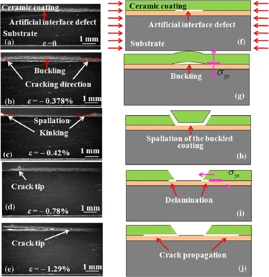
Fig.5 The morphology of TBCs with a prefabricated interface crack during fracture at different compressive strains and their corresponding failure mechanism schemes.a,f TBCs with a prefabricated crack.b,g ε=−0.378%and visible buckling occurred.c,h ε=−0.42%and the buckled coating rapidly spalls.d,i Crack originates at the end of buckling coating.e,j Crack propagates along the interface and results in spallation of coating

Then,the interface energy release rate G can be calculated by[29,30]

Obviously,the critical compressive stress changes as the increaseoftheinterfacecracklengthb,andthustheinterface energyreleaserate G isafunctionofb.SubstitutingEqs.(4), (5),the interface energy release rate G can be rewritten as

Thus,the fracture energyfrom an interface crak is the function of an energy release rate,that is

where w is the specimen width.Finally,the energy released by an interface buckling crack or the AE energy can be obtained asOnce the conversion coefficien α is known,the interface crack length b can be quantitatively determined.

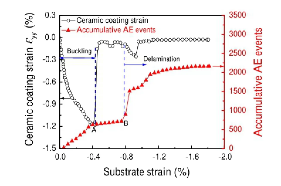
Fig.6 The evolution ofcompressive strainat point Minceramiccoating and cumulative AE events during compressive fracture
In a coating/substrate system with an imperfect interface, stress in the coating cannot be directly obtained by the load on the substrate.Thus,the strain evolution in the coating is recorded by a digital image correlation method.The applied stress-strain and stress-time curves are recorded by compressiontest.Itiseasytogettherelationshipbetweenapplied strain and time by eliminating the intermediate variable of stress.Meanwhile,the AE data and strain in the coating are recorded according to loading time.Therefore,it is easy to get the relationship between monitored strain in the coating or AE data and applied strain according to its correlation with time.Thus,the correlation of the strain data and AE data can be presented to analyze.As shown in Fig.6,the evolution of strain,along the y direction at point M in the coating,can be divided into two stages.In the firs stage,the compressive strain in the coating increases with an increase in the applied strain on the substrate and reaches a peak of −1.2%at a substrate strain of−0.42%.According to the AEbehavior,suchapeakistheendofthefirs fracturestage. Then,straininthecoatingreturnstozeroduetostressrelease associated with the buckling spallation of coating,and fluc tuates around zero during the second stage of the AE curves, indicating that there is no crack formation due to the absence of strain accumulation and release.In the third stage,compressivestraininthecoatingaccumulateswithanincreaseof substrate strain from−0.78%,corresponding to the nucleation of cracks,and then gradually attains its second peak of−0.29%with a sudden release at−0.9%of substrate strain.
Repeated compressive tests showed that due to irregular incubation of interface cracks,the lifetime in the second (or delamination)stage of fracture is seriously dispersed. For example,the delamination spallation of the coating occurred at about−1.29%shown in Fig.5e,whereas that for another specimen as shown in Fig.6 is about−0.9% of substrate strain.Therefore,the quantitative analysis of interface cracks is concentrated in the buckling stage without irregular incubation of crack due to artificia interface defect.The compressive loads of 275,285,295,305,and 310 MPa were chosen to quantify the relationship between the AE energy of an interface crack and the crack length 2b.The strain in the coating was monitored by digital image correlation as described in Fig.6,and the stress was obtained by Hooke’s law with an elastic modulus of 48 GPa and Poisson’s ratio of 0.22 of the ceramic coating[12,24].The calculated compressive stresses were 145, 196,250,295,and 346 MPa,respectively.The correspondingcracklengths2b obtainedfromexperimentalobservation were 5.4,6.2,7.2,8.6,and 10.8 mm.The conversion coefficien α between the interface crack energy and AE energy was 1.35×10⁸[31].Substituting these values and material parameters listed in Table 1 into Eq.(8),the AE energy could be calculated for each compressive load.During compression,the interface crack length and AE energy were recorded by CCD and AE systems,respectively.Figure 7 showed that the maximum error of AE energy between Eq. (8)andexperimentalresultsisabout20%,indicatingthatthe theoretical results are well consistent with those from experiment.Obviously,the AE energy increases with an increase of crack half length.It should be noted,however,that the AE energy only records those signals fromopening interface cracks.
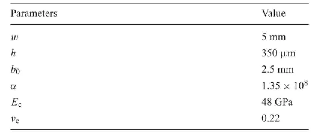
Table 1 The material parameters of TBCs used in Eq.(8)

Fig.7 The relationship of the AE energy and crack half-length during interface cracking associated with buckling
5 Conclusions
In this paper,the fracture behavior of TBCs with a prefabricatedinterfacecrackwasinvestigatedbytheAEmethod.The failure mode discrimination and quantificatio of interface cracks were realized.The main conclusions can be summarized as follows:
(1)There are four failure types in TBCs during an interface fracture process,including opening interface cracking, surfaceverticalcracking,slidingcracking,andsubstrate deformation.
(2)The failure process of TBCs with a prefabricated interface defect can be divided into two stages.One is buckling of coating at the defect dominated by opening interface cracks,and the other is delamination associated with sliding interface cracks.
(3)There is a quantitative relationship between the AE energy and interface cracks.
AcknowledgmentsThisworkwassupportedbytheNationalNatural Science Foundation of China(Grants 11472237,11002122,51172192, and 11272275).
References
1.Evans,A.G.,Mumm,D.R.,Hutchinson,J.W.,et al.:Mechanisms controlling the durability of thermal barrier coatings.Prog.Mater. Sci.46,505-553(2001)
2.Padture,N.P.,Gell,M.,Jordan,E.H.:Thermal barrier coatings for gas-turbine engine applications.Science 296,280-284(2002)
3.Schulz,U.,Peters,M.,Bach,F.W.,et al.:Graded coatings for thermal,wear and corrosion barriers.Mater.Sci.Eng.A 362,61-80 (2003)
4.Busso,E.P.,Wright,L.,Evans,H.E.,et al.:A physics-based life prediction methodology for thermal barrier coating systems.Acta Mater.55,1491-1503(2007)
5.Veal,B.W.,Paulikas,A.P.,Hou,P.Y.:Tensile stress and creep in thermally grown oxide.Nat.Mater.5,349-351(2006)
6.Chen,X.,Hutchinson,J.W.,He,M.Y.,et al.:On the propagation and coalescence of delamination cracks in compressed coatings: Withapplicationtothermalbarriersystems.ActaMater.51,2017-2030(2003)
7.Hutchinson,J.W.,He,M.Y.,Evans,A.G.:The influenc of imperfections on the nucleation and propagation of buckling driven delaminations.J.Mech.Phys.Solids 48,709-734(2000)
8.Aktaa,J.,Sfar,K.,Munz,D.:Assessment of TBC systems failure mechanisms using a fracture mechanics approach.Acta Mater.53, 4399-4413(2005)
9.Wu,R.T.,Wang,X.,Atkinson,A.:On the interfacial degradation mechanisms of thermal barrier coating systems:Effects of bond coat composition.Acta Mater.58,5578-5585(2010)
10.Yang,L.,Zhou,Y.C.,Lu,C.S.:Damageevolutionandrupturetime prediction in thermal barrier coatings subjected to cyclic heating and cooling:An acoustic emission method.Acta Mater.59,6519-6529(2011)
11.Yao,W.B.,Dai,C.Y.,Mao,W.G.,etal.:Acousticemissionanalysis on tensile failure of air plasma-sprayed thermal barriercoatings. Surf.Coat.Technol.206,3803-3807(2012)
12.Yang,L.,Zhong,Z.C.,Zhou,Y.C.,et al.:Quantitative assessment ofthesurfacecrackdensityinthermalbarriercoatings.ActaMech. Sin.30,167-174(2014)
13.Renusch,D.,Schütze,M.:Measuring and modeling the TBC damage kinetics by using acoustic emission analysis.Surf.Coat. Technol.202,740-744(2007)
14.Ma,X.Q.,Takemoto,M.:Quantitative acoustic emission analysis of plasma sprayed thermal barrier coatings subjected to thermal shock tests.Mater.Sci.Eng.A 308,101-110(2001)
15.Fu,L.,Khor,K.A.,Ng,H.W.,et al.:Non-destructive evaluation of plasma sprayed functionally graded thermal barrier coatings.Surf. Coat.Technol.130,233-239(2000)
16.Kucuk,A.,Berndt,C.C.,Senturk,U.,et al.:Influenc of plasma spray parameters on mechanical properties of yttria stabilized zirconia coatings.I:Four point bend test.Mater.Sci.Eng.A 284, 29-40(2000)
17.Yang,L.,Zhou,Y.C.,Mao,W.G.,et al.:Real-time acoustic emission testing based on wavelet transform for the failure process of thermal barrier coatings.Appl.Phys.Lett.93,231906(2008)
18.Yang,L.,Zhou,Y.C.,Mao,W.G.,et al.:Acoustic emission evaluation of the fracture behavior of APS-TBCs subjecting to bondcoating oxidation.Surf.Interface Anal.39,761-769(2007)
19.Gutkin,R.,Green,C.J.,Vangrattanachai,S.,et al.:On acoustic emissionforfailureinvestigationinCFRP:Patternrecognitionand peak frequency analyses.Mech.Syst.Signal Process.25,1393-1407(2011)
20.Benson,P.M.,Vinciguerra,S.,Meredith,P.G.,et al.:Laboratory simulation of volcano seismicity.Science 322,249-252(2008)
21.Landis,N.:Micro-macro fracture relationships and acoustic emissions in concrete.Constr.Build.Mater.13,65-72(1999)
22.Lu,C.S.,Mai,Y.W.,Shen,Y.G.:Optimuminformationincrackling noise.Phys.Rev.E 72,027101(2005)
23.Sause,M.G.R.,Haider,F.,Horn,S.:Quantificatioof metallic coating failure on carbon fibe reinforced plastics using acoustic emission.Surf.Coat.Tecnnol.204,300-308(2009)
24.Qian,G.,Nakamura,T.,Berndt,C.C.:Effects of thermal gradient and residual stresses on thermal barrier coating fracture.Mech. Mater.27,91-110(1998)
25.Mao,W.G.,Dai,C.Y.,Zhou,Y.C.,et al.:An experimental investigation on thermo-mechanical buckling delamination failure characteristicofairplasmasprayedthermalbarriercoatings.Surf.Coat. Tecnnol.201,6217-6227(2007)
26.Zhu,W.,Yang,L.,Guo,J.W.,et al.:Determination of interfacial adhesion energies of thermal barrier coatings by compression test combined with a cohesive zone finit element model.Int.J.Plast. 64,76-87(2015)
27.Wright,P.K.,Evans,A.G.:Mechanismsgoverningtheperformance of thermal barrier coatings.Curr.Opin.Solid-State Mater.Sci.4, 255-265(1999)
28.Nusair Khan,A.,Lu,J.,Liao,H.:Effect of residual stresses on air plasma sprayed thermal barrier coatings.Surf.Coat.Technol.168, 291-299(2003)
29.Hutchinson,J.W.,Suo,Z.G.:Mixedmodecrackinginlayeredmaterials.Adv.Appl.Mech.29,63-191(1991)
30.Wang,J.S.,Evans,A.G.:Measurement and analysis of buckling and buckle propagation in compressed oxide layers on superalloy substrates.Acta Mater.46,4993-5005(1998)
31.Yang,L.,Zhong,Z.C.,You,J.,et al.:Acoustic emission evaluation of fracture characteristics in thermal barrier coatings under bending.Surf.Coat.Technol.232,710-718(2013)
8 February 2015/Revised:1 March 2015/Accepted:25 March 2015/Published online:16 September 2015
✉Li Yang
lyang@xtu.edu.cn
1Key Laboratory of Key Film Materials&Application for Equipment(Hunan Province),School of Materials Science and Engineering,Xiangtan University,Xiangtan 411105, China
2Key Laboratory of Low Dimensional Materials&Application Technology(Ministry of Education),School of Materials Science and Engineering,Xiangtan University,Xiangtan 411105,China
3Department of Mechanical Engineering,Curtin University, Perth,WA 6845,Australia
杂志排行
Acta Mechanica Sinica的其它文章
- Impact toughness of a gradient hardened layer of Cr5Mo1V steel treated by laser shock peening
- A cavitation model for computations of unsteady cavitating flws
- Tomographic PIV investigation on coherent vortex structures over shark-skin-inspired drag-reducing riblets
- Analysis of the geometrical dependence of auxetic behavior in reentrant structures by finit elements
- The equilibrium stability for a smooth and discontinuous oscillator with dry friction
- An efficien formulation based on the Lagrangian method for contact–impact analysis of flexibl multi-body system
