Impact toughness of a gradient hardened layer of Cr5Mo1V steel treated by laser shock peening
2016-09-06WeiguangXiaLeiLiYanpengWeiAiminZhaoYacongGuoChenguangHuangHongxiangYinLingchenZhang
Weiguang Xia·Lei Li·Yanpeng Wei·Aimin Zhao·Yacong Guo· Chenguang Huang·Hongxiang Yin·Lingchen Zhang
Impact toughness of a gradient hardened layer of Cr5Mo1V steel treated by laser shock peening
Weiguang Xia1·Lei Li2·Yanpeng Wei1·Aimin Zhao3·Yacong Guo1· Chenguang Huang1·Hongxiang Yin3·Lingchen Zhang4
©The Chinese Society of Theoretical and Applied Mechanics;Institute of Mechanics,Chinese Academy of Sciences and Springer-Verlag Berlin Heidelberg 2015
AbstractLaser shock peening(LSP)is a widely used surface treatment technique that can effectively improve the fatigue life and impact toughness of metal parts.Cr5Mo1V steel exhibits a gradient hardened layer after a LSP process. A new method is proposed to estimate the impact toughnessthatconsidersthechangingmechanicalpropertiesinthe gradient hardened layer.Assuming a linearly gradient distribution of impact toughness,the parameters controlling the impact toughness of the gradient hardened layer were given. The influence of laser power densities and the number of laser shots on the impact toughness were investigated.The impact toughness of the laser peened layer improves compared with an untreated specimen,and the impact toughness increases with the laser power densities and decreases with the number of laser shots.Through the fracture morphology analysis by a scanning electron microscope,we established that the Cr5Mo1V steel was fractured by the cleavage fracture mechanism combined with a few dimples.The increase in the impact toughness of the material after LSP is observed because of the decreased dimension and increased fraction of the cleavage fracture in the gradient hardened layer.
KeywordsLaser shock peening·Gradient hardened layer·Plastically affected depth·Impact toughness· Cleavage fracture
1 Introduction
Laser shock peening(LSP)is an advanced surface treatment technique that has been successfully applied to improve the wear resistance and impact performance of metallic components[1-3].During an LSP process,a shock wave with high-amplitudepressureisgeneratedandpropagatesintothe target material through the interaction of a high-power density pulsed laser and a thin absorption layer on the target surface.Plastic deformation occurs,and plenty of dislocationsaregeneratednearthematerialsurfaceoncethepressure oftheshockwaveexceedstheHugoniotelasticlimit(HEL)of thematerial.Thus,residualcompressivestressesareinduced in the shocked region,resulting in a hardened layer near the target surface,which displays good performance considering wear and impact.It was found by Yasnii et al.[4]that the impact toughness of 15Kh13MF steel increases up to twofold after LSP with a power density ranging from 5×10⁸to 2×10⁹W·cm−2.The mechanism of the increase of impact toughness is mainly from two aspects:residual stresses and dislocations in the hardened layer[1,5-9].Prefabricated residual compressive stress can improve the stress threshold of crack growth.Using a laser quenching technique,Kong and Zhang[6]introduced residual compressive stresses into the 40CrNiMo steel,and the residual compressivestresscaneffectivelyretraincrackextensionandimprove impacttoughnessofthesample.Additionally,therefinemen ofcrystallinegrainorthegenerationofdislocationanddeformation twinning can effectively restrain the generation of acrack.ByreducingthemeangrainsizeofaMg-3Al-Znalloy to less than 3µm,Liao et al.[7]reported that the impact toughness is greatly improved due to enhancement of the dynamic strength and dynamic plastic deformation ability.It wasreported byMatset al.[9]that theincreaseoftheimpact toughness for the steel 15Kh2NMFA upon high-temperature ultrasonic treatment of various durations is due to the formation of a uniform defect structure.For the LSP processing technology,the mechanical properties of the hardened layer are not uniform[1,2,10-12].By the micro-hardness tests acrosstheLSPpeenedlayer,Peyreetal.[10]reportedthatthe hardness decreases gradually from surface to the base material.Using the X-ray diffraction(XRD)measurement,Dane et al.[11]reported that the residual compressive stresses induced by LSP process are gradually decreased along the depth and finall reach a level identical to the base material. Nodiscontinuitysurfaceisgeneratedattheinterfacebetween the hardened layer and base material.Thus,the laser peened layer can be seen as a gradient hardened layer(GHL)whose impact toughness needs to be investigated comprehensively.
Although the integral impact toughness of a structural component is the main concern in the engineering application,the local impact toughness of GHL given in this study hasitsadvantages.Whenthelocalimpacttoughnessofaconfiguratio is determined,the integral impact toughness can becalculatedthroughaspecifi model.Evenmoreimportant, theintegralimpacttoughnessofvariousgeometricconfigura tionscanalsobepredictedthroughthelocalimpacttoughness of GHL for the same processing parameters that may save much cost of detection.
In this paper,the laser peened layer of Cr5Mo1V steel is considered to be a GHL.The control parameters of impact toughness of GHL are define for a linearly gradient distribution.The value of the control parameters is experimentally determined from Charpy impact tests and hardness tests using an empirical equation.Additionally,the influence of laser power densities and the number of laser shots on the impacttoughnesswereinvestigated.Thefracturemechanism ofGHLwascharacterizedonascanningelectronmicroscope (SEM).
2 Experimental
2.1Materials
Cr5Mo1V steel materials were provided by the University of Science and Technology of Beijing(China).The nominal alloy composition is shown in Table 1.The steel was heattreated inafurnace at 850-870◦Cfor3-4 h,andthen cooled to 740-760◦C for 3-4 h,and then cooled in the furnace to 50◦C,and finall cooled in the air.The microstructure consistsofbimodal crystallinegrainswhose size variesfrom 15 to 90µm(see Fig.1).Prior to LSP,the specimen surface was ground with sandpaper and finall polished with 50 nm SiO2of turbid liquid.

Table 1 The composition of Cr5Mo1V steel(wt%)
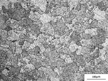
Fig.1 The microstructure of Cr5Mo1V steel

Fig.2 The schematic of LSP experiment
2.2LSP experiment
Figure 2 shows the schematic of the LSP experiment.The shocked surface of the Cr5Mo1V steel sample is glued with an aluminum foil(40µm thick)as an ablative overlay,and confine by flwing water against the laser irradiation.The aluminum foil is meanwhile used to increase the shock wave intensity and to protect the sample surface from laser ablation and melting.The flwing water is used to confin the expanding plasma to obtain higher shock pressure. Another Cr5Mo1V steel sample was attached to the back of the Cr5Mo1V steel specimen to match the impendence.A Q-switched high power Nd:YAG pulsed laser(Spectra Physics)operating at 1064 nm wavelength was used in the LSP experiment.The maximum output energy of a singlelaser pulse is 2.4 J and the pulse width(full width at half maximum)is about 10 ns.A focusing lens was utilized to adjust the laser spot size in order to obtain different laser power densities.The laser power density varied from 2.6 to 4.4 GW·cm−2.
2.3Property characterizations
The micro-hardness of the LSP-treated specimen was measured by a MH-6 micro-hardness tester with a load of 200 g and a holding time of 10 s at room temperature.The depth of the GHL of the Cr5Mo1V specimen after LSP was obtained throughamicro-hardnessdistributionalongthecross-section of LSP-treated specimen.The surface micro-hardness of the shocked region was measured to characterize the surface strengthening effect.
At room temperature,the Charpy impact test was performed using an impact testing machine with a JBDW-300D pendulum bob for samples treated with LSP.The Charpy specimenswerepreparedaccordingtotheGB/T229standard test method for Charpy pendulum impact of metallic materials[13].As the laser spot size is small(at the level of 3 mm),massive laser shots were applied on the sample surface in order to obtain a large laser-treated area.The overlapping ratiowas60%controlledbyanx-ytable.Theshockedregion isshowninFig.3,withadimensionof10 mm×8 mm.Both of the two sides are peened by LSP.To obtain a greater depth of the peened layer,different numbers of laser shots were used,varying from one to fi e shots.After the impact test, the impact energy of each sample was recorded.
2.4Microstructure observations
A scanning electron microscope(Nova NanoSEM operated at10kV)wasusedtocharacterizetheCharpyimpactfracture morphology.
3 Results and discussion
3.1Modeling of the impact toughness of a gradient
hardened layer
The classical impact toughness is defineas ak=Ak/A undertheassumptionthatmechanicalpropertiesinthecrosssection are uniform,where Akis the impact work,and A is the cross-section area[14-17].Moreover,Zhou et al. [14]reported that the average impact toughness of 2Crl3 martensitestainlesssteelincreasedasthelaserpowerdensity increased(within an appropriate range).However,the material treated by LSP presents nonuniformity,and the increase in the impact toughness is mainly attributed to the hardened layer.However,the classical equation cannot reflec the impact toughness of the gradient hardened layer because of the dimensional effect.
The distribution of impact toughness of GHL can be perceived as a function of depth.To simplify the model,the function is assumed to be linear according to the hardness and residual stress distribution tests across the peened layer section of former studies[10,11].By measuring the microhardnessacrossthecross-sectionoftheGHL,Peyreetal.[10]foundthatthehardnessesdecreasesalmostlinearlyalongthe depth and finallreach a level identical to the base material.The impact toughness is highest at the surface of the specimen and decreases linearlyalong the GHL.The highest impacttoughnessofGHLisdenotedasak1inthetopsurface. The impact toughness of the base material is denoted as ak0. Thus,the gradient of the impact toughness from surface to the boundary,denoted as k,can be calculated as follows:

where h is the depth of the GHL layer after LSP.Therefore, the impact toughness during the peened layer can be calculated as follows:

Fig.3 Scheme of the laser shock peening and dimensions of the specimen
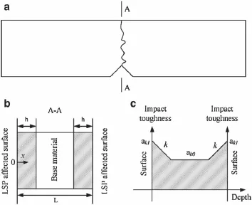
Fig.4 ModelingtheimpacttoughnessoftheGHL.aTheschematicof afractureoftheCharpyspecimen.bThecross-sectionofalaserpeened layer.c The distribution of the impact toughness at the cross-section of the peened layer

where x is the distance from the surface to the internal peened layer,as shown in Fig.4.The parameters controlling the impact toughness of the gradient hardened layer are thesurface impact toughness,ak1,andthegradient,k,forthe assumption of linearly gradient distribution of impact toughness during the peened layer.
Charpy impact tests are widely used to determine the impact toughness of material[18-20].Figure 4a shows the schematic of fracture of a Charpy specimen at impact load. Figure 4b shows the cross-section including the laser peened layer and the base material.Figure 4c shows the distribution of the impact toughness at the cross-section.To simplify the model,several assumptions are drawn:
(1)The crack propagation surface is always perpendicular to the head surface.
(2)The mechanical properties are assumed to have a linearlygradient distributionduringthelaserpeenedlayer. The properties of the GHL boundary are equal to the properties of the base material.

During the Charpy impact tests,the impact work is obtained.ThefracturesofboththeGHLandthebasematerial contribute to the impact work.Therefore,the surface impact toughness after LSP can be calculated as follows: where,b is the distance from the notch to the undersurface (seeFig.3),and Akistheimpactwork.Theimpacttoughness of the base material,ak0,can be obtained from an untreated sample.The depth of GHL,h,has a significan influenc on thesurfaceimpacttoughness,ak1,andthegradient,k,inEqs. (1)and(3).The depth of GHL,h,can be obtained from the distribution of the micro-hardness along the cross-section of a laser peened specimen.Therefore,the surface impact toughness after LSP can be calculated from Eqs.(1)and(3).
3.2Depth of the GHL
The depth of GHL can be obtained through the microhardness distribution along the cross-section of laser peened sample[10-12].According to Chen et al.[21]and Carlsson andLarsson[22],theinducedresidualcompressivestresscan enhance the hardness of material.Meanwhile,the improvement of impact toughness is also related to the compressive residual stress[6,8].So,we speculate that the gradients of the hardness and impact toughness have the similar distribution.Thus,the hardness along the cross-section of peened sample can be used to determine the depth of GHL.Using the micro-hardness test,the depth of GHL of the Cr5Mo1V steeltreatedwithdifferentlaserpowerdensitiesanddifferent numbers of shots was measured,as shown in Fig.5a,b.For thesampletestatalaserpowerdensityof3.8 GW·cm−2,the micro-hardness test along the cross-section of a laser-treated sample shows that the micro-hardness increases at the surfaceoftheGHL,andthengraduallydecreasestothevalueof theuntreatedregionatadepthof(1.00±0.05)mm,asshown in Fig.5a.The result indicates that the thickness of GHL is (1.00±0.05)mm at a laser power density of 3.8 GW·cm−2. The depth of the GHL at other laser parameters can be obtained through this method.The relationship between the depthoftheGHLandlaserpowerdensityisshowninFig.6a. The depth of the GHL increases with laser power density for laser power densities lower than 3.8 GW·cm−2and slightly decreasesatlaserpowerdensitieshigherthan3.8GW·cm−2. This behavior is because the laser induced shock pressure is proportionaltothesquarerootoflaserpowerdensityaccordingtoFabbro’smodel[23],i.e.,thehigherlaserpowerdensity is,the higher the laser induced shock pressure is.According totheresearchofBallardetal.[24],plasticallyaffecteddepth is proportional to the difference between shock pressure and HEL.Thus,higher shock pressure induces deeper plastically affected depth.That is why the depth of GHL increases with laser power density when the laser power density is lower than 3.8 GW·cm−2.However,when the laser power density exceeds a critical value,the surface of the confinin overlay will become opaque to the laser.Thus,the effective laser energy on the shocked surface will decrease.As a result,the depth of GHL will decrease.That is why the depth of GHLslightly decreases while the laser power density increases to 4.4 GW·cm−2.
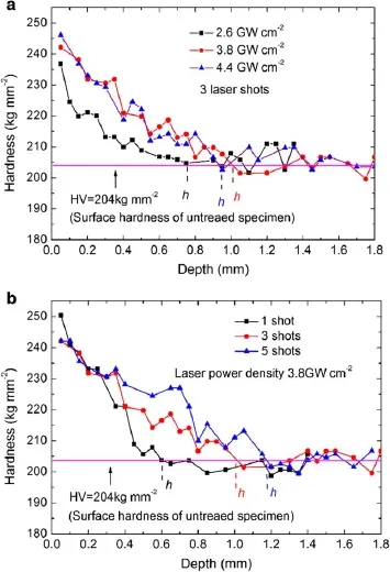
Fig.5 Hardnessasafunctionofdepthonthecross-sectionofapeened sample:adifferentlaserpowerdensitiesand bdifferentnumberoflaser shots
Figure 6b shows the relationship between the depth of the GHL and the number of laser shots.The depth of GHL is proportional to the laser shots,which is consistent with the experimental resultsofDaneetal.[11]andMasseetal.[25]. It was found by Dane et al.[11]that the depth of residual compressive stressesgenerated bytwosuccessivelasershots is higher than that of a single shot.Also,Masse et al.[25]found that the plastically affected depth increases from 0.86 to 1.80 mm when the number of laser shots increases from one to three.So the more the number of laser shots are,the higher the depth of GHL is.

Fig.6 The plastically affected depth of different laser power densities and numbers of laser shots:a different laser power densities and b different numbers of laser shots
3.3Impact toughness
From the Charpy impact tests,the impact work is shown in Table 2.The impact work increases with increasing laser power densities when the laser power density is lower than 3.8 GW·cm−2.When the laser power density exceeds
3.8GW·cm−2,the impact work is almost unchanged.The depthoftheGHLalsohastheidentical trendwiththeimpact work.Based on Eqs.(1)-(3)combined with the depth of the GHL,the surface impact toughness,ak1,and the gradient,k,of the peened samples can be calculated as shown in Fig.7a.The impact toughness and the gradient k both increase as the laser power density increases from 2.6 to 4.4 GW·cm−2.This increase is consistent with Zhou et al. [14]whose results demonstrate that the impact toughness of the 2Crl3 martensite stainless steel increases with increasing laser power densities when the laser power density is lower than 8.57 GW·cm−2.The reason for this increase is due to the residual compressive stress induced by a laser induced shockwhichcanrestrainthegrowthofthecrack[1,2,14,26]. As the residual compressive stress increases with increasing laser power densities within an appropriate range,the surfaceimpacttoughnessincreaseswiththelaserpowerdensity.This can be reflecte through the surface hardness afterLSP.In Table 2,the surface hardness increases from 236.8 to 246.1 kg·mm−2as the laser power density increases from 2.6 to 4.4 GW·cm−2,which has the identical trend with the experimental results of Clauer and Fairand[27].Clauer and Fairand[27]found that the average surface hardness of 2024-T351 increases with peak shock pressure while the peakpressureisproportionaltothesquarerootoflaserpower density.The increase in the gradient can be ascribed to the fact that the increasing rate of impact toughness is higher than the increasing rate of the depth of the GHL according to Eq.(1).

Table 2 Characteristics of the GHL with different laser power densities
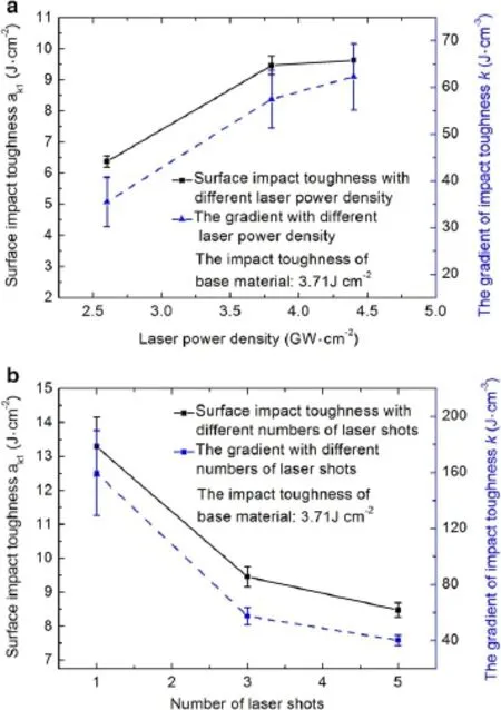
Fig.7 Impact toughness,ak1,and the gradient,k,for different laser power densities and different numbers of laser shots:a different laser power densities and b different numbers of laser shots
The impact work with different numbers of laser shots is shown in Table 3.Comparing with untreated samples, the impact work increases after LSP.The increase in the impact work shows no dependence on the numbers of laser shots.According to Eqs.(1)-(3)and the depth of the GHL, the impact toughness,ak1,and the gradient,k,of a peened specimen can be calculated as shown in Fig.7b.As the impact work is almost unchanged,and the depth of the GHL increases with the numbers of laser shots,the surface impact toughness decreases with the numbers of laser shots according to Eq.(3).The gradient k of the peened samples also decreases with increasing numbers of laser shots according to Eq.(1).Using finit element analysis to simulate the LSP process of 35CD4 steel alloy,Ding and Ye[28]reported that the surface compressive residual stress is almost unchanged while the plastically affected depth increases from 0.74 to 1.4mmwhenthenumbersoflasershotsincreasesfromoneto three.Surfacecompressiveresidualstressplaysanimportant role on the magnitude of surface impact toughness through restraining the generation and growth of crack.As a result, the gradient k decreases with increasing the number of laser shot according to our model,due to the fact that the depth of GHL increases rapidly while the surface compressive residual stressisalmost unchanged withincreasingthenumber of laser shots.
3.4Mechanisms of fracture of treated specimens
Figure 8 shows the fracture mechanism of specimens treated with laser induced shock at the laser power density of 4.4GW·cm−2with three laser shots.Figure 8a shows the fracture morphology from an LSP-treated surface to an untreatedregion.Themainmechanismoffractureiscleavage fracture combined with a few dimples.The microstructure of a fracture surface is similar to a river pattern.The dimension of the cleavage fracture decreases from the surface to the untreated region.Cleavage fracture with smaller dimensions can absorb more energy during fracture,resulting in higherimpactwork.Figure8b-dshowthemorphologyofthe cleavage fractures from untreated region to the LSP treated surface.Figure 8b shows the morphology of the cleavage fractures of the untreated region.The number of cleavage fractures is relatively low and the dimensions of cleavage fracturesarelarge,atthelevelof80-90µm.Figure8cshows the morphology of the cleavage fractures at the region away from the surface of the GHL.The number of cleavage fractures increases,and the dimension of the cleavage fracture (at the level of 50-60µm)is smaller compared with the untreatedregion.Therefore,theimpacttoughnessintheGHL ishigherthantheuntreatedregiontoughnessastheincreased cleavagefracturescanabsorbmoreenergyduringtheimpact. Figure 8d shows the morphology of the cleavage fractures beneath the surface of the GHL.This region has the largest number of cleavage fractures and smallest dimensions(at the level of 25-35µm)of the cleavage fracture.Thus,more energycanbeabsorbedduringimpact.Therefore,theimpact toughness is higher at the LSP-treated surface and decreases along the depth of the GHL as the dimension of the cleavage fracture increases with depth.Thus,the GHL is formed during the laser induced shock.The increased number of cleavage fractures and decreased dimension of the cleavage fractures are due to the residual compressive stresses and density of dislocations induced by the laser shock wave.It wasreported byTrdan etal.[26]that ashock wave generates residual compressive stresses to a depth of above 0.78 mm, and density of dislocations with various types,including dislocation cells,dislocation lines,dislocation tangles,and the formation of dislocation walls for the Al-Mg-Si alloy.At the same time,the microstructure of the material is rather refine due to the effect of strain deformations induced by the LSP process.As a result,the impact toughness increasesbecause of the increased number and decreased dimensions of the cleavage fractures.

Table 3 Characteristics of GHL with different numbers of laser shots

Fig.8 Fracture morphology of a laser peened Charpy specimen for a laser power density of 4.4 GW·cm−2and three laser shots.a Fracture morphology from the LSP-treated surface to the untreated region.b Amplifie image of cleavage fractures from region B of the untreated region. c Amplifie image of cleavage fractures from region C in the GHL.d Amplifie image of cleavage fractures from region D beneath the LSP-treated surface
4 Conclusions
The Cr5Mo1V steel was processed by laser shock peening,and a GHL was exhibited.A new method to estimate the impact toughness that considers the GHL was proposed. When assuming a linearly gradient distribution for impact toughness,the parameters describing the impact toughness ofthepeenedlayerwereprovided.Theinfluence ofthelaser power densities and number of laser shots on the impact toughness were investigated.The impact toughness of the laser peened layer improves when compared with untreated specimens,and increases in the laser power densities and decreasesinthenumberoflasershotsalsoimprovethetoughness.Through the fracture morphology analysis by SEM, we established that the Cr5Mo1V steel was fractured by a cleavage mechanism combined with a few dimples.The increase in the impact toughness of the material after LSP results from the cleavage fracture with smaller dimensions and increased fraction component in the fracture process. Therefore,Cr5Mo1V steels with higher impact toughness canbepreparedwithLSPforapplicationsintherollindustry.
AcknowledgmentsThe project was supported by the National Natural Science Foundation of China(Grants 11002150,11332011,and 11402277)and the Basic Research Equipment Project of the Chinese Academy of Sciences(YZ200930)for financia support.
References
1.Montross,C.S.,Wei,T.,Ye,L.,etal.:Lasershockprocessingandits effects on microstructure and properties of metal alloys:a review. Int.J.Fatigue 24,1021-1036(2002)
2.Peyre,P.,Fabbro,R.:Laser shock processing:a review of the physics and applications.Opt.Quantum Electron.27,1213-1229 (1995)
3.Zhang,Y.K.,Lu,J.Z.,Luo,K.Y.:Laser Shock Processing of FCC Metals,1st edn.Springer,Berlin(2013)
4.Yasnii,P.V.,Marushchak,P.O.,Nikiforov,Y.M.,et al.:Influenc of laser shock-wave treatment on the impact toughness of heatresistant steels.Mater.Sci.46,425-429(2010)
5.Shukla,P.P.,Lawrence,J.:Fracture toughness modificatioby using a fibr laser surface treatment of a silicon nitride engineering ceramic.J.Mater.Sci.45,6540-6555(2010)
6.Kong,D.J.,Zhang,L.:Effects of laser quenching on impact toughness and fracture morphologies of 40CrNiMo high strength steel. J.Mater.Eng.Perform.23,3695-3702(2014)
7.Liao,J.S.,Hotta,M.,Kaneko,K.,etal.:Enhancedimpacttoughness of magnesium alloy by grain refinement Scripta Mater.61,208-211(2009)
8.Chaudhury,J.N.:Effect of heat treatment,pre-stress and surface hardening on fracture toughness of micro-alloyed steel.J.Mater. Eng.Perform.23,152-168(2014)
9.Mats,A.V.,Netesov,V.M.,Sokolenko,V.I.:Dislocation structure andimpacttoughnessofreactorpressurevesselsteel15Kh2NMFA upon ultrasonic treatment.Strength Mater.43,515-518(2011)
10.Peyre,P.,Fabbro,R.,Merrien,P.,et al.:Laser shock processing of aluminium alloys.Application to high cycle fatigue behaviour. Mater.Sci.Eng.A 210,102-113(1996)
11.Dane,C.B.,Hackel,L.A.,Daly,J.,et al.:Laser peening of metalsenabling laser technology.Adv.Mater.Process.5,13-27(1997)
12.Wang,X.,Xia,W.G.,Wu,X.Q.,etal.:MicrostructureandmechanicalpropertiesofanausteniteNiTishapememoryalloytreatedwith laser induced shock.Mater.Sci.Eng.A 578,1-5(2013)
13.GB/T229-2007:Standard Test Method for Charpy Pendulum Impact of Metallic Materials.Standards Press of China,Beijing (2007).(in Chinese)
14.Zhou,P.C.,Feng,A.X.,Nie,G.F.,etal.:Impacttoughnessof2Cr13 martensitestainlesssteelinducedbylaser.LaserInfrared42,1235-1238(2012).(in Chinese)
15.Marushchak,P.O.,Bishchak,R.T.,Gliha,B.,et al.:Influenc of temperatureontheimpacttoughnessanddynamiccrackresistance of 25Kh1M1F steel.Mater.Sci.46,568-572(2011)
16.Zhang,N.,Shi,Y.W.,Xia,Z.D.,etal.:ComparisonofimpacttoughnessandfracturemorphologiesbetweenPb-containingandPb-free solder joints subject to the Charpy impact test.J.Electron.Mater. 37,1631-1639(2011)
17.Barbangelo,A.:Influenc of alloying elements and heat treatment on impact toughness of chromium steel surface deposits.J.Mater. Sci.25,2975-2984(1990)
18.Buirette,C.,Huez,J.,Gey,N.,et al.:Study of crack propagation mechanisms during Charpy impact toughness tests on both equiaxedandlamellarmicrostructuresofTi-6Al-4Vtitaniumalloy. Mater.Sci.Eng.A 618,546-557(2014)
19.Yang,X.L.,Xu,Y.B.,Tan,X.D.,et al.:Influence of crystallography and delamination on anisotropy of Charpy impact toughness in API X100 pipeline steel.Mater.Sci.Eng.A 607,53-62(2014)
20.Demirci,M.T.,Tarakcioglu,N.,Avci,A.,et al.:Fracture toughness of filamen wound BFR and GFR arc shaped specimens with Charpy impact test method.Compos.B 66,7-14(2014)
21.Chen,X.,Yan,J.,Karlsson,A.M.:Onthedeterminationofresidual stress and mechanical properties by indentation.Mater.Sci.Eng. A 416,139-149(2006)
22.Carlsson,S.,Larsson,P.L.:On the determination of residual stress and strain field by sharp indentation testing.:Part I:theoretical and numerical analysis.Acta Mater.49,2179-2191(2001)
23.Fabbro,R.,Fournier,J.,Ballard,P.,et al.:Physical study of laserproducedplasmainconfine geometry.J.Appl.Phys.68,775-784 (1990)
24.Ballard,P.,Fournier,J.,Fabbro,R.,etal.:Residualstressesinduced by laser-shocks.J.Phys.IV 1,487-494(1991)
25.Masse,J.E.,Barreau,G.:Surface modificatioby laser induced shock waves.Surf.Eng.11,131-132(1995)
26.Trdan,U.,Skarba,M.,Grum,J.:Laser shock peening effect on the dislocation transitions and grain refinemen of Al-Mg-Si alloy. Mater.Charact.97,57-68(2014)
27.Clauer,A.,Fairand,B.:Interaction of laser-induced stress waves with metals.In:Metzbower,E.(ed.)Metals Park,pp.291-315. American Society for Metals,Ohio(1979)
28.Ding,K.,Ye,L.:Simulation of multiple laser shock peening of a 35CD4steelalloy.J.Mater.Process.Technol.178,162-169(2006)
8 March 2015/Revised:6 April 2015/Accepted:3 May 2015/Published online:21 September 2015
✉Yanpeng Wei
weiyanpeng@imech.ac.cn
1Key Laboratory for Mechanics in Fluid Solid Coupling Systems,Institute of Mechanics,Chinese Academy of Sciences,Beijing 100190,China
2Sinosteel Scie-tech Development Company Limited, Beijing 100080,China
3Metallurgical Engineering Research Institute,University of Science and Technology Beijing,Beijing 100083,China4Center of Library and Information,Institute of Mechanics, Chinese Academy of Sciences,Beijing 100190,China
杂志排行
Acta Mechanica Sinica的其它文章
- Correcting the initialization of models with fractional derivatives via history-dependent conditions
- A cavitation model for computations of unsteady cavitating flws
- Tomographic PIV investigation on coherent vortex structures over shark-skin-inspired drag-reducing riblets
- Analysis of the geometrical dependence of auxetic behavior in reentrant structures by finit elements
- The equilibrium stability for a smooth and discontinuous oscillator with dry friction
- Why a mosquito leg possesses superior load-bearing capacity on water:Experimentals
