An efficien formulation based on the Lagrangian method for contact–impact analysis of flexibl multi-body system
2016-09-06PengChenJinYangLiuJiaZhenHong
Peng Chen·Jin-Yang Liu·Jia-Zhen Hong
An efficien formulation based on the Lagrangian method for contact–impact analysis of flexibl multi-body system
Peng Chen1·Jin-Yang Liu1·Jia-Zhen Hong1
©The Chinese Society of Theoretical and Applied Mechanics;Institute of Mechanics,Chinese Academy of Sciences and Springer-Verlag Berlin Heidelberg 2015
AbstractIn this paper,an efficien formulation based on the Lagrangian method is presented to investigate the contact-impact problems of fl xible multi-body systems. Generally,the penalty method and the Hertz contact law are the most commonly used methods in engineering applications.However,these methods are highly dependent on various non-physical parameters,which have great effects on the simulation results.Moreover,a tremendous number of degrees of freedom in the contact-impact problems will influenc thenumericalefficien ysignificantl.Withtheconsideration of these two problems,a formulation combining the component mode synthesis method and the Lagrangian method is presented to investigate the contact-impact problems in fl xible multi-body system numerically.Meanwhile, the finit element meshing laws of the contact bodies will be studied preliminarily.A numerical example with experimentalverificatio willcertifythereliabilityofthepresented formulationincontact-impactanalysis.Furthermore,aseries of numerical investigations explain how great the influenc of the finit element meshing has on the simulation results. Finallythelimitationsoftheelementsizeindifferentregions are summarized to satisfy both the accuracy and efficien y.
KeywordsMulti-body dynamics·Contact-impact
analysis·Lagrangian method·Component mode synthesis
1 Introduction
In mechanical systems,contact-impact processes are frequently investigated.Due to their discontinuity and characteristics of high nonlinearity,it is difficul to describe this mechanical behavior in dynamic systems.
When the fl xibility of the contact bodies is concerned, the resulted wave propagation should be investigated,which is a high frequency phenomena.For decades,the issue of contact-impact analysis in fl xible multi-body system has always been a research focus.The key points of this problem seemtobetheevaluationofthecontactforceandthedescriptionoftheinducedwavepropagationinafl xiblemulti-body system.
In recent years,researchers proposed many classic theories and contact force models.There are mainly two approaches to evaluate the contact force.The firs approach, namely the continuous force models[1],assumes that the contact force can be expressed explicitly by fictitiou parameters and the state variables of the contact bodies,such as the Hertz contact theory[2-4]and the penalty method[5]. These parameters can be evaluated analytically or experimentally[6].Forsolvingcontact-impactproblemsinfl xible multi-body systems,the continuous force model shows great efficien y.An investigation by Flores[7]showed the influenc of different contact-impact force models on the dynamic response of multi-body systems.In this work,the choice of model parameters and indexes was also stated.In theworkofSeifried[8],thecoefficien ofrestitutionwasevaluated numerically for the investigation of repeated impacts, similar works combined with experimental researches can be seen in Schiehlen[9-11]and Seifried[12,13].Also, Lankarani[14]investigated the effect of contact damping. It was found that when dealing with practical engineeringproblems,the contact damping effects should be considered. However,for various contact force models,the definition of these non-physical parameters are different,and in many cases they are difficul to determine accurately.
The second approach to evaluate the contact force is the Lagrangian method[4,15],which will be employed in this paper.Without the assumption that the contact effect is a force element,the Lagrangian method treats the interaction asconstraints,sothatthecontactforcecanbeevaluatedbythe Lagrange multiplier formulation[16-18];therefore,it is not necessarytorelyonindefinit parameters.However,sincethe modal reduction approach can not be applied,a tremendous number of degrees of freedom in the contact-impact problems will influenc the numerical efficien y significantl.
The aspects of wave propagation in a fl xible multibody system also need special notice.The floatinframe of reference formulation is a typical method to describe the multi-body system with small elastic deformation.In common investigations,the complete finitelement model is mostly used for contact analysis;however,it is very time consuming because of the tremendous number of degrees of freedoms.Based on this consideration,Schiehlen et al.[9]proposedamodelcombinedfromtwosubmodels,anonlinear finit element(FE)model to describe the local deformation resulting from the contact-impact,and a modal model to describe the global elastodynamic behavior.Herein,another technique named the component mode synthesis method [19,20],canbeusedinthemodelingofthesystem.Bydefin ingthenodaldisplacementsofthecontactregionandthejoint connecting region as the boundary degrees of freedom,the simulationofthehighlynonlinearbehaviorwithinthecontact region is fairly precise.Because the interior nodal displacementscanbeexpressedbyasetofmodalcoordinatescoupled with the boundary degree of freedoms(DOFs)in the manner of the component mode synthesis method,as a consequence, the total DOFs of the system decrease significantl.
In practical applications,the element size of the finit elementmodelsplaysanimportantroleinthenumericalsimulations.However,no such general laws on this aspect are concluded.In this paper,some limitations on the maximum element size of different regions of the contact bodies are investigated.
The paper is organized in the following manner.Firstly, the formulation of fl xible multi-body systems based on the floatinframe of reference method will be obtained using the component mode synthesis technique.Then the contactimpact kinematic description and constraint implementation will be discussed,and the complete governing equations of the fl xible multi-body system with contact-impact are derived.Finally,the theoretical formulations are illustrated by numerical simulations.A typical numerical example is introduced to verify the proposed formulation by the comparison with the experiment result,and the penalty method is also investigated to show the drawbacks.Furthermore,the influence of the element size on the simulation results are discussed,and a few finit element meshing laws will be concluded.
2 Dynamic formulation of flexibl multi-body systems
2.1Kinematic description of a flexibl body
For modeling fl xible multi-body systems experiencing small elastic deformations,the well-known floatinframe of reference formulation is most widely used.In this paper, both the rigid body motion and the elastic deformation are considered for the contact bodies,so this formulation will be used.AsdepictedinFig.1,twoframesaredefine todescribe the configuratio of a fl xible body,where e0is the inertial frame,and ebis the body-fi ed frame.The global position vector of an arbitrary point define in e0can be written as

Within the reference frame,the relative position vector define in ebcan be depicted as

where Aiisthetransformationmatrix,whichdefine theorientation of the body-fi ed frame with respect to the inertial frame,ρ′
i0is the position vector in the un-deformed state described in the body-fi ed frame,and u′iis the deformation displacement vector described in the body-fi ed frame, which can be approximated by

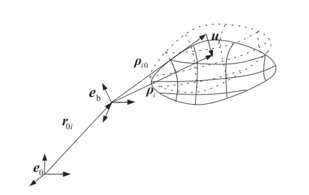
Fig.1 Description of a flxible body
where Niis the shape function matrix,and piis the array of nodal deformation coordinates.In contact-impact analy-sis,piwill be a large dimension vector,when coupled with the rigid body motion coordinates,the system appears to be difficul to solve.Considering the situation of a small deformation,thecomponentmodesynthesistechniquecanbeused to reduce the dimension of pi.

By usingthistechnique,pican be partitioned intoboundaryandinteriordegreesoffreedom,asrepresentedbyEq.(4) Consideringanelasticcomponentexperiencingfreestructural vibration,the linearized equations of motion are given in the following form


According to Eq.(4),the structural matrices can be partitioned as Next,by introducing the Craig-Bampton method of component mode synthesis[21],a shape function is define as a transformation matrix

whereΦKisasetofselectedfi ed-interfacecomponentnormal modes,which is obtained by performing a eigenvalue analysis for matrices mI Iand kI I,and the set of constraint modes ΦCtakes the form


Then,atransformationfromfinit elementcoordinates pito component mode synthesis generalized coordinates y can be performed,which is given by where yi=akTpTJT,and akis the vector of modal coordinates corresponding to the normal modes.Finally,the configuratio of a single fl xible body can be described by a set of generalized coordinates

where r0iand θirepresent the translation and rotation coordinates of the floatin frame of body i,and in this paper the vector of Carden angles θi=α β γTare used to describe the rotation of the fl xible body.
Let ω′ibe the vector of angular velocity definein the body-fi ed frame,by differentiation of Eq.(1)and using the body-fi ed frame,by differentiation of Eq.(1)and using the expression At=Aiw and p==-p[23],.the global velocity of an arbiary point can be espressed as

where

Andω˜iρ˜irepresent the skew matrices corresponding toω′i,ρ′i,respectively.
By differentiation of Eq.(11),the acceleration vector of an arbitrary point can be expressed as

where

Consideringtherelationshipbetweentheangularvelocity vector and the time derivative of the Carden angles ω′i= Kb˙qi[23],a transformation can be performed

where Kbis a 3×3 matrix,which is the function of qi. Differentiation of Eqs.(16)leads to

2.2Dynamic equations of a flexibl body
The governing equations of a general fl xible multi-body system considering contact-impact can be derived using the Lagrangian method,based on the principle of virtual power. For a single fl xible body,the power of the external,internal, and inertial forces applied to the body must vanish

where Eiand Siare the strain and stress vectors,and ΔPiEis the virtual power of the external forces,which is used to obtain the vector of generalized external forces fiE

Substituting Eqs.(11)and(13)into the firs term of Eq.(18),the virtual power done by the inertial forces can be written as

where

In the situation of a small deformation analysis,a linear relationbetweenthestrainvectorandthedeformationvector exists,and according to Eq.(9),the virtual power of the internal forces takes the form

where kiis the stiffness matrix.Considering Eq.(14),this item can be written as

where fSiis the vector of the internal forces

Substituting Eqs.(19),(20)and(23)into Eq.(18),the dynamicvariationalequationsofafl xiblebodyareobtained as

Substituting Eqs.(16)and(17)into Eq.(25),the variational equations of motion read

where

2.3Contact–impact description
For frictionless contact problems,the well-known Kuhn-Tucker condition[22]can be stated as

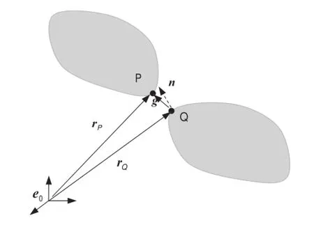
Fig.2 Description of a gap function
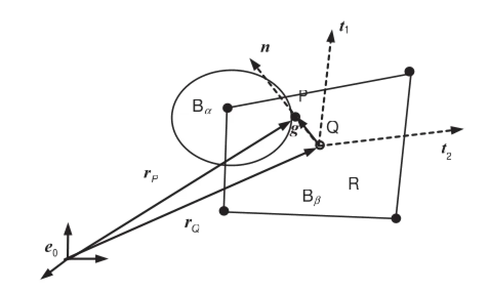
Fig.3 Description of a contact pair
where gNis the gap function in a normal direction between point P and its projection point Q,as demonstrated in Fig.2. When gNequals zero,the contact takes place,and a normal component of the stress vector will take effect.
In an actual situation,the contact-impact behavior is an interactionbetweentwoareasofdifferentbodies.However,it isalmostimpossibletodescribethisinteractioninsimulation. With the finit element approximation,a set of contact pairs will be efficien to formulate the contact.
For a contact pair in discrete form,a slave node P and a matching master segment R are define first as shown in Fig.3.Then the projection point Q in the segment corresponding to the slave node P can be determined,and a local coordinate system with an origin of Q is established accordingly.
Intheformulationofacontinuousforcemodel,thenormal gap function is allowed to be negative,which means the penetrationexists.Ageneralrelationbetweenthenormalcontact force and the penetration reads as

Then,a couple of resisting forces acting on the points P and Q take effect,which are equal and opposite

However,the stiffness parameter P relies on the material behavior and the mesh properties,and it is not definite In practice,this parameter is obtained by a convergence procedure.When a small stiffness is taken,the contact force shows a low amplitude and long duration characteristics.On thecontrary,itisnumericallydifficul tosolvewhenthestiffness is too large.
Toavoidnon-physicalparameters,theLagrangianmethod can be used.When a contact pair is activated,a set of constraint equations should be added to the system

This constraint equation restricts the slave node P from penetratingthemastersegment,whichwillberemovedwhen the contact pair is detected to be separate.
When the contact pair P-Q is activated for the firs time, point P and Q should have the same velocity in the normal direction,whichmeansanumericalprocessingwillbeimplemented[20].
In time discretization form,the time derivative formulation of the constraint equations seems to be more convenient to use.If the contact-impact process is very short,we ignore the time derivative terms of nj,and then twice the derivative of Eq.(31)can be given as

According to Eq.(13),it reads as

In this paper,the contact-impact of a fl xible multi-body system is investigated.The vector of the generalized coordinates of the system is assembled by q=qT1qT2···qTN
T,
and the relation between qiand q is given by

The assembled constrained equations associated with contact-impact are given by

Substituting Eqs.(16)and(34)into Eq.(33),the acceleration constraint equation can be expressed as

where ΦCqjis the Jacobian matrix of the j-th contact pair, which is given by

Takingallthecontactpairsintoaccount,thetotalJacobian matrix of the contact constraint equations can be assembled as

Itmightalsobenotedthatthenumberoftheactivatedcontact pairs is time-variant,so the size of thisJacobian matrix changes with time.
2.4Dynamic equations of a flexibl multi-body system
Foranunconstrainedsystem,thedynamicequationscansimply be assembled by Eq.(26),which read

where
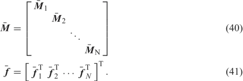
The motion of fl xible bodies represented by Eq.(38)is independent of each other without constraints.
Forconstrainedfl xiblemultibodysystems,theconstraint equations aredenoted byΦJ,andtheJacobian matrixisΦJq. Then,the dynamic equations of a fl xible multi-body system with contact-impact are expressed as

where λJand λCare the vectors of Lagrange multipliers correspondingtothejointconstraintsandthecontact-impact constraints,respectively.Typically,it is a set of differentialalgebraic equations combined with the constraint equations ΦJ=0 and ΦC=0.Equations of motion(42)are solved combined with the acceleration equation

where γJand γCare the right sides of the acceleration equations corresponding to the joint constraints and the contact-impact constraints,respectively.
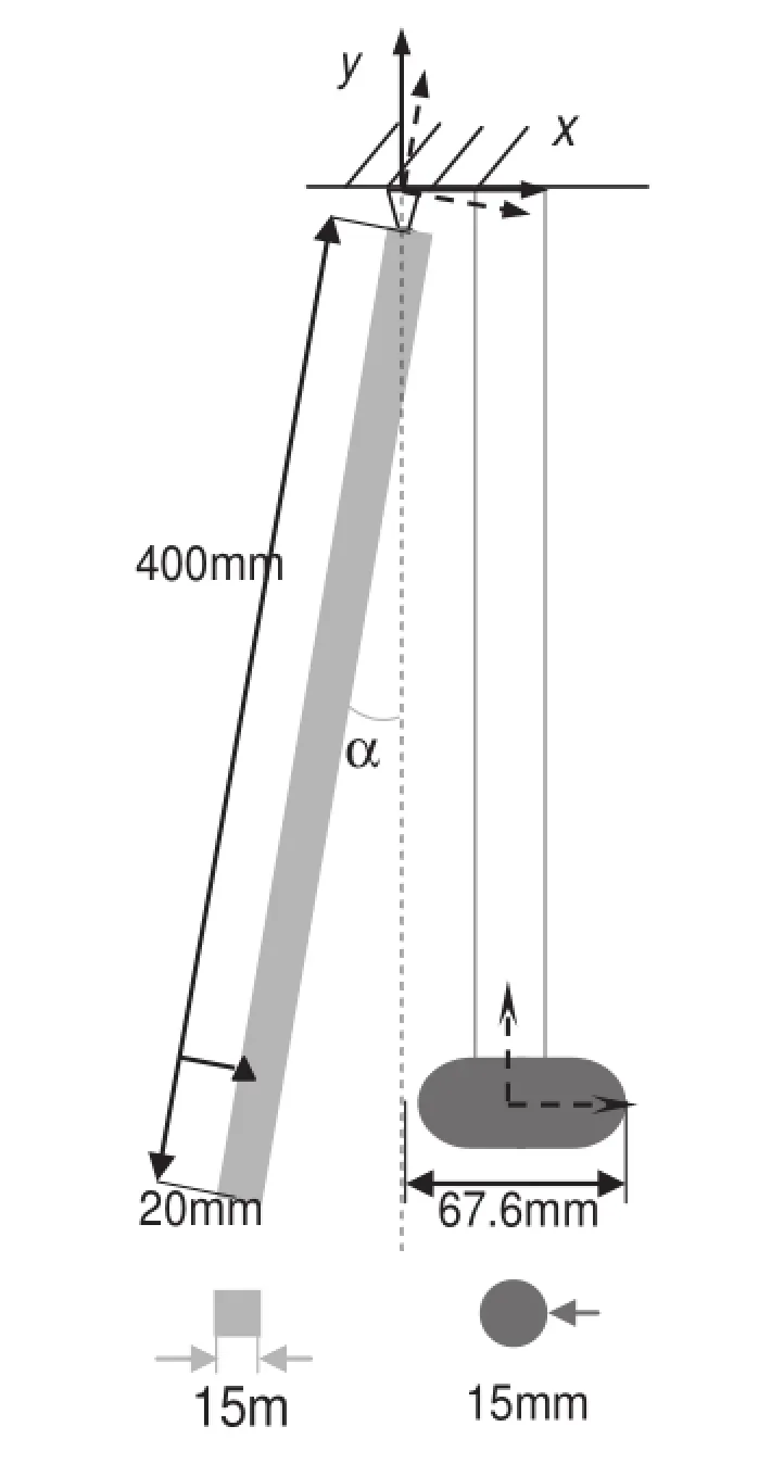
Fig.4 Impact between a steel pendulum and an aluminum rod

Table 1 Material data of the two bodies
3 Numerical examples
To verify the formulation proposed in this paper,a typical fl xible multi-body system with joint constraints will be investigated.This system consists of a steel pendulum and a suspendedaluminumrod;thegeometriesareshowninFig.4, and the material data of the two bodies are summarized in Table 1.The pendulum is released from an initial angle and impacts with the rod when the pendulum falls to the vertical position.This example was presented by Seifried et al.[12], which was simulated using the penalty method and verifie experimentally.
3.1The verificatio of the proposed formulation
To verify the formulation proposed in this paper,the experimental results in Ref.[12]will be used as a reference.A contact process with 2 milliseconds is simulated,and the time history of the velocity of the point marked by a black triangle in Fig.4 is given,which is right behind the contact point on the pendulum.As a comparison,the simulation result of Ref.[12]is also given.
AsshowninFig.5,theformulationproposedinthispaper issufficientl preciseinthesimulationofthecontact-impact process of the fl xible multibody system.In addition,the DOF used in this formulation is much less than the finit element method.As for this example,153 nodes and 20 modal coordinates are used to describe the rod instead of total 2261 nodes,while 128 nodes and 20 modal coordinates are used to describe the pendulum instead of 5373 nodes.Therefore, the DOFs needed to describe the deformation of the contact bodies are reduced remarkably,which can be seen from Table 2.
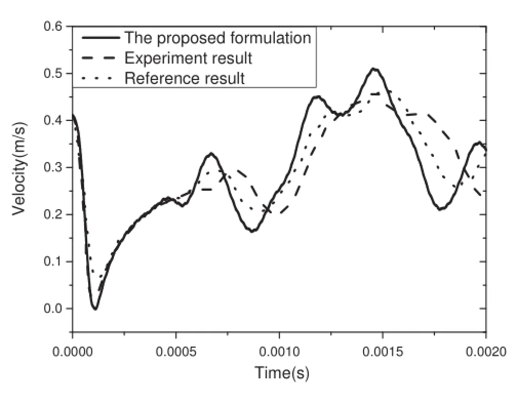
Fig.5 Time history of the pendulum velocity by different approaches

Table 2 DOFs to describe the deformation
3.2Comparison of the Lagrangian method and the penalty method
The penalty method is highly dependent on various nonphysical parameters.For the simulation of contact-impact problems,differentsetsofcontactstiffnesswillleadtototally differentresults,whiletheLagrangianmethodisindependent on any parameters.
The time history of the contact force and the velocity of the pendulum in the line of impact are given in Figs.6 and 7.The formulation proposed in this paper is labeled as theLagrangianmethod,asacomparison,thepenaltymethod by LS-DYNA is implemented with a list of incremental contact stiffness.Figures 6 and 7 show a typical convergenceprocedure,for the uncertainty of the contact stiffness,differentsetsofstiffnessmustbetesteduntilthesimulatedcontact force converges.

Fig.6 Time history of contact force by different models
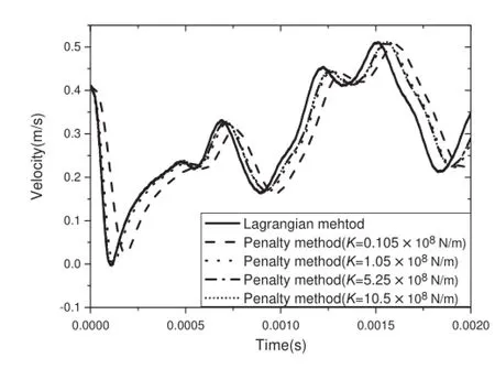
Fig.7 Pendulum velocity in the line of impact
3.3Finite element mesh of the contact bodies
For the investigation of the contact-impact problems,the high frequency of the wave propagation must be considered, which means that there is a restriction on the maximum element size[6].Furthermore,the contact region should be discretized with sufficien contact elements to guarantee the accuracy of the contact force,and the mesh size in the impactdirectionofcertainregionisstricterthanotherinterior regions.
As shown in Fig.8,the pendulum in this example is divided into the contact region and the interior region.To investigate the influenc of the mesh size on the simulation results,4 sets of pendulum meshes will be used,while the rod meshes are the same and dense enough.The maximum element size in different regions of the meshes is given in Table 3.

Fig.8 Schematic of the pendulum

Table 3 Maximum element size in different regions
The contact force and the velocity of the back point of the pendulum in the impact direction are depicted in Figs.9 and 10,simulated by four sets of pendulum meshes. It can be obviously seen that the maximum element size of the contact bodies has a significan influencon the numerical results.The precision of the interior mesh size affects not only the wave propagation,but also the contact force.
It can be concluded as follows:
(1)To simulate the wave propagation precisely,the smallest interesting wavelength should be discretized by at least 20elements,whichhasthesameconclusionasthatgiven by Seifried in the literature[6].The maximum element size in wave propagation becomes

In this example,the interesting maximum frequency of the pendulum is about 30 kHz from the experimentalresults,so that the maximum element size in the wave propagation is about 8.5 mm.
(2)In the impact direction,special attention should be paid tothemeshsize,especiallywhenthelengthinthisdirection is relatively small.In this example,the maximum element size in the impact direction is only one-fourth of the element size of other regions.General laws will be investigated in the follow-up studies.
(3)Withinthecontactregion,sufficien contactpairsshould be guaranteed to obtain an accurate simulation result. In this example,the contact region is a circle with a radius of about 0.8 mm,and the model with mesh 1, which has an element size of 0.6 mm,can provide only 4 contact pairs.By the investigation of this kind of low speed impact problems,we can conclude that at least 9 contact pairs are needed.
(4)With an optimized mesh that uses different grids in different regions,a small amount of elements are enough to satisfy the accuracy of the simulation,and this will improve the efficien y significantl.
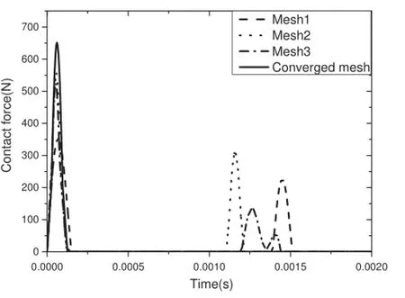
Fig.9 Contact force by different meshes
3.4Application to a flexibl multi-body system
To apply this formulation to a complicated fl xible multibody system,a slider-crank mechanism involving contact is investigated.AsshowninFig.11,4bodiesareinvolvedinthis system,the geometrical and material parameters are listed in Table 4.
The crank B1 can be considered as a rigid body,while B2,B3,and B4 are modeled as fl xible bodies.The crank is driven by a coil spring with a stiffness of 5N·M/rad,and the initial angle θ1is set as 0.29 rad.All frictions are ignored and the gravity acceleration is given by 9.8m/s2.
The contact force between B3 and B4 is given by Fig.12, and the constraint force of the joint between B2 and B3 in x and y directions are given by Fig.13.

Fig.11 A slider-crank mechanism involving contact

Table 4 Geometrical and material parameters of the bodies
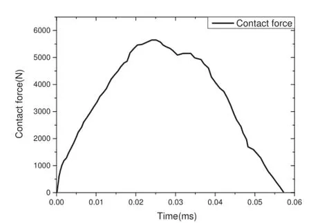
Fig.12 Time history of the contact force

Fig.13 Time history of the constraint force
4 Conclusions
This article focuses on two problems existing in contactimpactanalysisofafl xiblemulti-bodysystem,theaccuracy ofthecontactmodel,andtheefficien yoftheentireformulation.A formulation combining the component mode synthesismethodandtheLagrangianmethodispresented.Different from the penalty method,the proposed formulation is independent of the non-physical parameters.Consequently,the contactmodelismoreaccuratewithoutestimatingthecontact stiffness.Furthermore,theuseofcomponentmodesynthesis method can significantl reduce the degrees of freedom of the system.
For contact-impact analysis,the finitelement mesh determines the accuracy of the simulation results.Therefore, the limitations of the maximum element size of the contact bodies are investigated in this paper.By applying different element sizes in different regions,an optimized mesh can be obtained,which can avoid using a large number of unnecessary elements.
AcknowledgmentsThe project was supported by the National Science Foundation of China(Grants 11132007,11272203).
References
1.Gilardi,G.,Sharf,I.:Literature survey of contact dynamics modelling.Mech.Mach.Theory 37,1213-1239(2002)
2.Goldsmith,W.:Impact.Courier Dover Publications,New York (2001)
3.Timoshenko,S.P.,Gere,J.M.,Prager,W.:Theory of Elastic Stability.J.Appl.Mech.29,220(1962)
4.Taylor,R.L.,Papadopoulos,P.:On a finit element method for dynamic contact/impact problems.Int.J.Numer.Methods Eng. 36,2123-2140(1993)
5.Lankarani,H.M.,Nikravesh,P.E.:A contact force model withhysteresisdampingforimpactanalysisofmultibodysystems.J.Mech. Des.112,369-376(1990)
6.Seifried,R.,Hu,B.,Eberhard,P.:Numerical and experimental investigation of radial impacts on a half-circular plate.Multibody Syst.Dyn.9,265-281(2003)
7.Flores,P.,Ambrósio,J.,Claro,J.C.P.,et al.:Influencof the contact-impactforcemodelonthedynamicresponseofmulti-body systems.Proceedings of the Institution of Mechanical Engineers, Part K:Journal of Multi-body Dynamics 220,21-34(2006)
8.Seifried,R.,Schiehlen,W.,Eberhard,P.:Numerical and experimental evaluation of the coefficien of restitution for repeated impacts.Int.J.Impact Eng.32,508-524(2005)
9.Schiehlen,W.,Seifried,R.,Eberhard,P.:Elastoplastic phenomena in multibody impact dynamics.Comp.Methods Appl.Mech.Eng. 195,6874-6890(2006)
10.Schiehlen,W.,Guse,N.,Seifried,R.:Multibody dynamics in computational mechanics and engineering applications.Comp. Methods Appl.Mech.Eng.195,5509-5522(2006)
11.Schiehlen,W.,Seifried,R.:Impactsystemswithuncertainty//IUTAM symposium on dynamics and control of nonlinear systems with uncertainty.Springer,Netherlands(2007)
12.Seifried,R.,Schiehlen,W.:Computational analysis and experimental investigation of impacts in multibody systems//IUTAM Symposium on Multiscale Problems in Multibody System Contacts.Springer,Netherlands(2007)
13.Seifried,R.,Schiehlen,W.,Eberhard,P.:The role of the coeffi cient of restitution on impact problems in multi-body dynamics. Proceedings of the Institution of Mechanical Engineers,Part K: Journal of Multi-body Dynamics 224,279-306(2010)
14.Lankarani,H.M.,Nikravesh,P.E.:Continuouscontactforcemodels for impact analysis in multibody systems.Nonlinear Dyn.5,193-207(1994)
15.Heinstein,M.W.,Mello,F.J.,Attaway,S.W.,etal.:Contact-impact modeling in explicit transient dynamics.Comp.Methods Appl. Mech.Eng.187,621-640(2000)
16.Dong,F.X.,Hong,J.Z.,Zhu,K.,etal.:Numericalandexperimental studies on impact dynamics of a planar fl xible multibody system. Acta Mech.Sin.26,635-642(2010)
17.Weyler,R.,Oliver,J.,Sain,T.,etal.:Onthecontactdomainmethod: acomparisonofpenaltyandLagrangemultiplierimplementations. Comp.Methods Appl.Mech.Eng.205,68-82(2012)
18.Han,S.L.,Hong,J.Z.:Multi-variable method for fl xible multibodysystemswithcontact/impact.Chin.J.Theor.Appl.Mech.43, 886-893(2011)
19.Bauchau,O.A.,Rodriguez,J.:Formulation of modal-based elements in nonlinear,fl xible multibody dynamics.Int.J.Multiscale Computat.Eng.1,161-180(2003)
20.Chen,P.,Liu,J.Y.,Hong,J.Z.:Contact-impact formulation for multi-body systems using component mode synthesis.Acta Mech. Sin.29,437-442(2013)
21.Castanier,M.P.,Tan,Y.C.,Pierre,C.:Characteristic constraint modes for component mode synthesis.AIAA J.39,1182-1187 (2001)
22.Wriggers,P.:Finiteelementalgorithmsforcontactproblems.Arch. Comput.Methods Eng.2,1-49(1995)
23.Hong,J.Z.:Computational multibody dynamics.High Education Press,Beijing(1999)
8 February 2015/Revised:2 April 2015/Accepted:24 May 2015/Published online:16 September 2015
✉Jin-Yang Liu
liujy@sjtu.edu.cn
1Department of Engineering Mechanics,School of Naval Architecture,Ocean and Civil Engineering,Shanghai Jiaotong University,200240 Shanghai,China
杂志排行
Acta Mechanica Sinica的其它文章
- Impact toughness of a gradient hardened layer of Cr5Mo1V steel treated by laser shock peening
- A cavitation model for computations of unsteady cavitating flws
- Tomographic PIV investigation on coherent vortex structures over shark-skin-inspired drag-reducing riblets
- Analysis of the geometrical dependence of auxetic behavior in reentrant structures by finit elements
- The equilibrium stability for a smooth and discontinuous oscillator with dry friction
- Why a mosquito leg possesses superior load-bearing capacity on water:Experimentals
