旋转CVD技术及其在陶瓷粉体担载纳米粒子催化剂制备中的应用
2016-08-08张建峰後藤孝
张建峰,涂 溶,後藤孝
1河海大学 力学与材料学院,南京2100982武汉理工大学 材料复合新技术国家重点实验室,武汉4300703日本 东北大学金属材料研究所,仙台市980-8577,日本
旋转CVD技术及其在陶瓷粉体担载纳米粒子催化剂制备中的应用
张建峰1,涂溶2,後藤孝3
1河海大学 力学与材料学院,南京210098
2武汉理工大学 材料复合新技术国家重点实验室,武汉430070
3日本 东北大学金属材料研究所,仙台市980-8577,日本
担载型纳米粒子催化材料通常是指将金属或金属氧化物活性相以纳米粒子的形式分散到惰性担载陶瓷粉体表面而形成的复合粉体材料。提高纳米粒子催化材料的分散均匀性是获得高催化性能的关键。传统的溶胶-凝胶法、浸润法等处理步骤冗长,易导致纳米粒子的团聚长大,降低催化效果。流化床化学气相沉积方法则比较适合处理粒径在40 μm ~ 500 μm的担载粉体。本文着重介绍了粉体旋转化学气相沉积技术的原理,并以镍纳米粒子为例阐述了这种技术的相关应用。采用旋转化学气相沉积技术,在六方氮化硼 (hBN)、立方氮化硼 (cBN)、氧化铝 (Al2O3)、氧化硅 (SiO2) 等粉体表面沉积 (包覆) 了镍纳米粒子,显示出了优越的催化性能。本文同时分析了旋转化学气相沉积技术存在的问题及未来的研究前景。
旋转化学气相沉积技术;纳米粒子催化材料;均匀分散
在全球能源日趋匮乏以及排放标准不断提高的大背景下,开发高活性低成本催化剂 (如 Ni或Ni3Al),将天然气 (如甲烷) 重整制氢,成为重要的研究课题。典型的担载型催化剂一般是由活性相(如金属及金属氧化物) 和具有高比表面积的惰性陶瓷担载粉体 (如介孔二氧化硅、纳米氧化铝等)组成[1-4]。获得高催化活性的关键在于催化剂纳米粒子在担载粉体表面的均匀分散[5]。
目前担载型纳米粒子催化剂的主要制备方法有溶胶-凝胶法、浸润法和化学气相沉积 (CVD) 法等[6-12]。溶胶-凝胶和浸润等方法制备的担载型纳米粒子催化剂分散不够均匀,且纳米粒子尺寸分布较宽。对于浸润方法来说,由于纳米粒子是通过物理方式吸附到担载粉体表面,结合力较弱,因此纳米粒子容易团聚,在高温催化反应时易于团聚烧结,导致比表面积和催化活性的降低。化学气相沉积技术则可以克服这一缺点。在化学气相沉积过程中,纳米粒子通过前驱体气体的分解在担载粉体表面形核而生成,具有较高的分散度,并通过化学吸附与担载粉体表面形成较强的界面相互作用。由于催化剂纳米粒子是在接近于催化反应温度的条件下生成,因此具有很高的热稳定性。对于在平板上进行化学气相沉积来说,保证气相与生长表面的充分接触并不存在问题[13,14]。然而,由于粉体的团聚以及巨大的比表面积,通过化学气相沉积对粉体表面进行包覆时情况则完全不同,变得异常困难[5]。在如此大比表面积的粉体表面实现纳米粒子的均匀包覆成为研究者致力解决的问题。
流化床-化学气相沉积法通过将粉体流化,将大量固体颗粒悬浮于运动的流体之中,保证反应气体和粉末的良好接触,同时将液相或固相金属前驱体加热挥发,挥发气体进入反应室,在粉体表面分解沉积,从而实现粉体的包覆[15-18]。根据粉料密度和粒度特性的不同,研究者将粉体划分为A、B、C、D四类[5,19,20]。如图1所示,当粉体的平均颗粒尺寸在40 μm ~ 500 μm、固体颗粒密度在1400 kg/m3~4000 kg/m3之间时,属于B类粉体。这类粉体流化性最好,最适合进行流化床-化学气相沉积法处理。而粉体小于40 μm (A类或C类) 或大于500 μm时,由于难以达到稳定的流化态,不适于采用流化床-化学气相沉积法进行表面包覆。近年来,研究者对流化床-化学气相沉积技术进行了改进,喷射型流化床-化学气相沉积[21,22]、震动型流化床-化学气相沉积[23-25]以及循环流化床-化学气相沉积[26,27]等仪器及技术应运而生,拓宽了流化床-化学气相沉积技术的适用粉体范围,但增加了制备成本和技术难度。

1旋转CVD技术
旋转 CVD 方法是一种在粉体表面包覆纳米粒子的有效方法,具有包覆效果均匀、适用范围广等优点。Itoh等人[28,29]报道了一种旋转CVD方法,反应室采用透明的石英玻璃管,红外辐射加热炉加热粉体,以TiCl4-B2H6-H2和TiCl4-N2-H2作为反应体系,在鳞片石墨和钛粉表面包覆了TiN涂层。Santo等人[30]采用旋转CVD方法,以有机金属CVD方法制备了担载金属纳米粒子催化剂,因此可以制备10 g以上的具有优良催化性能的催化剂纳米材料。
笔者于2008年开始进行新型 (改进型) 旋转CVD仪器的研究开发,用于粉体的表面包覆与改性[31,32]。图2为仪器示意图,主要由反应室、原料罐、旋转控制、真空泵以及加热炉几部分组成。由于粉体在反应室内处于浮游状态,因此该仪器对需包覆的粉体没有粒径限制,可以实现40 μm以下粉体的包覆。与已有文献报道的类似仪器相比,该仪器有如下一些特点:
(1) 借助于原料罐内壁焊接的叶片,可以使被包覆粉体在原料罐旋转过程中不断从高处落下而处于浮游状态,进而使得粉体表面完全暴露于反应气体中;
(2) 可以通过调整旋转速度调整粉体在空中的停滞时间;
(3) 借助于磁性流体密封保持反应室内的真空度,实现反应室内压力的精确控制。

图2 旋转CVD仪器示意图 (右图为粉体在旋转过程中的运动示意图)Figure 2 Schematic of the rotary CVD apparatus. The left of the figure shows the simulation of the powder movement in the rotary process)
本文将以Ni金属催化剂纳米粒子为例,简要综述已取得的部分成果。在以下例子中,将Ni金属催化剂纳米粒子包覆到粉体表明的具体实验步骤为:将二茂镍原料2 g ~ 8 g放置于原料罐中加热至120°C ~ 150°C,由载气 (Ar) 携带至反应罐中,载气的流量控制在50 sccm。反应罐的加热温度为550°C,旋转速率控制在45 r/min。原料罐中粉体由于一直被叶片拨动旋转运动,处于悬浮 (浮游)状态,因此能够被均匀地包覆。反应完成后,取出粉体,采用X-射线衍射 (XRD)、扫描电镜 (SEM)等进行粉体形貌的表征,并根据具体的应用目标测试其相应的性能指标。
2立方氮化硼粉体包覆及其在制备碳纳米管中的应用
催化化学气相沉积法 (Catalytic chemical vapor deposition, CCVD) 是合成碳纳米管的常用方法。在过渡金属Fe、Co或Ni等催化剂的作用下,将含碳气体 (如甲烷、乙炔等) 或有机溶液 (苯、甲醇等) 在特定温度下催化分解或者直接热分解含有Fe、Ni等金属元素的有机化合物,即可生长出碳纳米管[11,33-36]。采用CCVD可以选择性地以多种形式生长碳纳米管,尤其是通过将催化剂负载到需要的载体上可以控制碳纳米管的表面生长位点,制备多种结构的碳纳米管,例如非晶型的碳层、碳纤维、石墨烯层以及单壁碳纳米管 (SWNTs) 和多壁碳纳米管 (MWNTs) 等。催化剂的制备与分散方法主要有溶胶-凝胶、浸渍法等。催化剂在载体上的分散状况是决定所获得的碳纳米管的形貌及产量的重要因素,例如高分散的催化剂可以降低沉积的碳量[37]。
笔者以二茂镍为原料,通过原位分解生成金属镍作为催化剂,在立方氮化硼 (cBN) 粉体表面一步合成了碳纳米管[38]。有趣的是,同样的实验条件下,在六方氮化硼 (hBN) 表面却未能形成碳纳米管。如图3所示,在hBN表面包覆的镍纳米粒子粒径约为20 nm左右,未看到碳纳米管的形成;而在cBN表面镍纳米粒子的粒径最小为10 nm,最大达到了50 nm左右,形成了长度为500 nm、外径20 nm ~ 50 nm的碳纳米管,且按照顶部生长模式生长。
导致这一差别的原因或许可以从热导角度进行分析。在CVD反应过程中,二茂镍通过如下反应生成镍纳米粒子,同时为石墨或碳纳米管的形成提供碳源[39-41]:

图3 包覆在(a,b) hBN和(c,d) cBN粉体表面上的镍纳米粒子的透射电镜照片[38]Figure 3 TEM images of Ni nano-particle precipitated on (a) hBN and (c) cBN. (b) and (d) are high magnification images of (a) and (c), respectively[38]

图4 镍包覆cBN及hBN粉体中碳的形成机理:路线 (1) 表示了碳纳米管的形成过程,路线 (2) 表示了石墨层包覆在镍表面的形成过程Figure 4 Carbon incorporation mechanism in Ni nano-particle precipitated cBN and hBN powders: the route (1) shows the growth process of carbon nanotubes, and the route (2) shows the formation process of only graphite layers on nickel
图4给出了碳纳米管形成机理示意图。式 (1) 反应后在hBN或cBN表面形成镍纳米粒子,随后C5H5+n继续加速分解。由于C5H5+n的分解是一个放热过程,在镍纳米粒子上部 (与气体接触部分)温度高于底部 (与hBN或cBN接触部分),从而形成了温度梯度,使得碳在镍中扩散到底部[42]。由于镍底部与担载粉体接触,担载粉体的热导率成为决定碳扩散的重要因素。镍、hBN和cBN的热导率分别为90 W·m-1·K-1、28 W·m-1·K-1~ 33 W·m-1·K-1和300 W·m-1·K-1~ 600 W·m-1·K-1[43.44]。cBN具有极高的热导率,能够将镍表面产生的热量迅速吸收,因此能够保持碳的持续扩散,从而导致了碳纳米管的底部生长模式[45]。而hBN热导仅为镍的三分之一左右,使得热量在镍本身聚集,分解的碳包覆在镍的表面,破坏了镍的继续催化作用,因而难以形成碳的接续生长,也就不可能生成碳纳米管。因此可以认为:hBN与cBN的热导差异大,导致了碳纳米管生成能力的差异。
3六方氮化硼粉体表面包覆及其在甲烷分解反应中的应用
天然气、汽油等的燃烧是造成温室效应以及雾霾天气的重要原因。选择新型能源以降低含碳原料的使用势在必行。甲烷是含氢量最大的烃,是天然气、沼气、油田气及煤矿坑道气的主要成分,在自然界的分布范围很广,可作为燃料及制造氢气、炭黑、一氧化碳、乙炔、氢氰酸及甲醛等物质的原料[46-48]。甲烷直接分解产生的氢气不需要进行纯化就可以应用于质子交换膜燃料电池,而分解产生的碳则可以用作直接碳燃料电池的燃料。
由于吸热反应的原因,甲烷分解的温度高达 1300°C,而使用催化剂则可以将分解温度降低到800°C以下,因此具有很好的应用前景,而高分散的催化剂则是降低分解温度并提高催化效果的关键因素[46]。用作催化剂担载体的传统材料 (包括SiO2、γ-Al2O3、沸石等) 往往具有低的热导率,会使得分散其上的金属纳米粒子烧结团聚,这些粉体本身的亲水性也会导致低温下催化剂被水覆盖侵蚀,从而导致催化剂活性的损失[48,49]。六方氮化硼具有较高的热导率和高温稳定性以及较好的化学惰性,而且本身也是一种疏水性材料,能够阻止表面水分的凝结,因此作为催化剂载体具有很大的优势。
笔者曾尝试采用hBN作为催化剂载体,采用旋转CVD技术将Ni纳米粒子分散到表面。图2显示,采用二茂镍在hBN粉体表面包覆了均匀分布的镍纳米粒子,引入氧气消除了由二茂镍碳氢基团产生的碳杂质污染[50]。Ni3Al是一种常用的催化材料,具有良好的制氢催化性能[51,52]。笔者以 Ni包覆的 hBN作为催化剂,以Ni3Al金属间化合物催化剂作为对比材料,进行了甲烷制氢的催化实验研究[53],结果如图 5所示。显然,采用Ni/hBN作为催化剂的情况下,甲烷转化率及制氢速率均高于对比材料Ni3Al。

图5 甲烷转化率与氢气产生速率随温度的变化关系Figure 5 The dependence of conversion of CH4and production rate of H2on temperature
4氧化铝粉体表面包覆及其在甲醇分解催化反应中的应用
我国的能源结构“缺油、富煤”,作为替代燃料的甲醇主要来自于煤化工和天然气合成,可以利用煤炭、天然气、煤层气等制成,在新能源汽车的热潮中发展前景广阔。通过高能量密度的甲醇或乙醇液体的催化转化即时产生氢气,是高效、安全利用氢气作为机车燃料的最佳选择。工业上利用甲醇制氢有甲醇分解、甲醇部分氧化和甲醇蒸汽重整等几种方法[54-57];在这些方法中,主要采用两种催化剂催化反应过程,一类为负载型贵金属催化剂,另一类为复合金属氧化物型催化剂。Al2O3具有较好的热导和化学惰性,是常用的催化剂担载材料 (氧化物)。为了测试旋转 CVD技术在不同粒径粉体表面包覆纳米粒子的可行性,笔者在不同粒径的 Al2O3粉体表面包覆了镍纳米粒子,研究了Al2O3粒径对于包覆的镍纳米粒子的形貌、粒径及催化性能的影响规律。
如图6[58]所示,当Al2O3粒径最小为80 nm、最大为150 μm时,均在粉体表面成功包覆了均匀分布的Ni纳米粒子,Ni纳米粒子的粒径最大为62.5 nm,最小为8 nm,这表明旋转CVD技术突破了流化床CVD的尺寸限制,对于粉体材料的包覆具有更大的适用范围。但值得注意的是,随着Al2O3粒径的增加,相应地粉体比表面积减小,暴露于反应气体中的可供镍纳米粒子着床的面积减小,因此沉积在其表面的镍纳米粒子数量减少,且由于纳米粒子接触及团聚的原因,粒径随之增大。
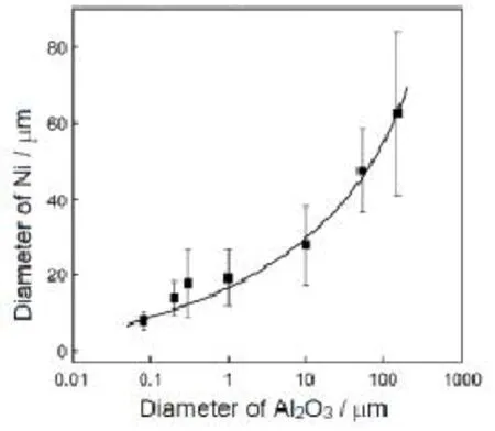
图6 Al2O3载体粉体粒径对包覆其表面的镍纳米粒子粒径的影响[58]Figure 6 Effect of particle size of Al2O3on the size of Ni particle forming on the surface of Al2O3powder[58]

图7 氢气产生速率与粉体的粒径、比表面积之间的关系[58]Figure 7 The dependence of production rate of H2on the particle size of Al2O3and specific area of Ni/Al2O3catalysts[58]
将制备的Al2O3担载Ni金属纳米粒子用于甲醇的分解催化实验 (CH4OH → CO + 3H2),结果如图7所示。随着粉体粒径的降低和比表面积的增加,氢气的产生速率随之增加。前已述及,流化床-化学气相沉积技术对于纳米粉体较难实现流化及表面均匀包覆处理[59-61]。而这一本研究则从粉体包覆角度实现了A类和C类粉体 (图1) 中表面镍纳米粒子的包覆,提供了一种提高催化剂催化性能的新思路和新技术。
5介孔二氧化硅孔道装载及其在甲醇分解反应中的应用
有序介孔材料于上世纪90年代迅速兴起,得到国际物理学、化学与材料学界的高度重视,并迅速发展成为跨学科的研究热点之一。介孔材料的发展,不仅将分子筛由微孔范围扩展至介孔范围,而且使得大分子吸附、催化反应、药物存储等得以实现,在吸附分离、化工催化、生物医药、功能材料等众多行业领域具有很好的应用前景[62,63]。按照化学组成,介孔材料可以分为硅系和非硅系两类,其中硅系介孔材料 (如MCM-41[64,65]、SBA-15[66-68]等) 具有表面积和孔道体积大、尺寸可控调节以及孔径分布较窄、可控、均一等特点,是目前研究较多的一类,技术也比较成熟。
选用介孔SiO2作为制备纳米镍、金等催化剂的载体,其大的比表面积及孔道结构可以使得纳米金属离子分散均匀且不易聚结长大,因而提高催化剂在反应中的稳定性[69,70]。目前主要的制备方法包括浸渍法、沉积-沉淀法和化学气相沉积法,同时还辅之以表面功能化修饰,以获得均匀分散的纳米粒子,并限域于介孔孔道内[68,71]。但表面修饰改性的制备时间较长,步骤繁琐,且表面改性剂的存在对目标反应有不利影响。笔者应用旋转CVD技术,通过保持介孔SiO2粉体 (介孔孔径为7.1 nm)处于浮游状态,将热分解产生的纳米粒子定向装载于介孔孔道内,获得了均匀分布的镍/氧化镍纳米粒子[72]。
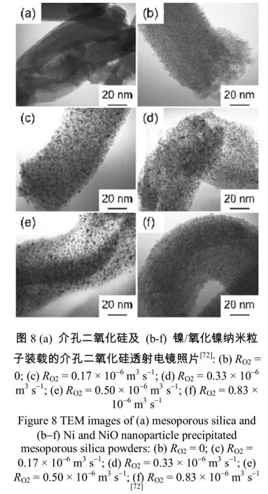
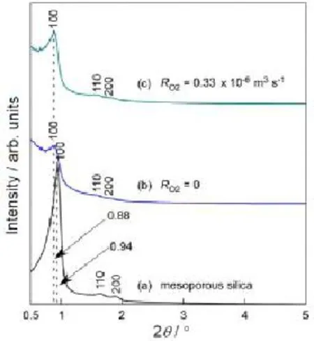
图9 (a) 介孔二氧化硅及 (b,c) 镍/氧化镍装载的介孔二氧化硅的小角X射线衍射图谱:(b) RO2= 0,(c) RO2= 0.33 × 10⁻⁶m3s-1 [72]Figure 9 LAXRD patterns of (a) mesoporous silica and Ni-precipitated mesoporous silica at (b) RO2= 0and (c) RO2= 0.33 × 10⁻⁶m3s-1[72]
如图8所示的TEM照片可以看出,纳米粒子的粒径为5 nm左右,略小于孔道尺寸。随着氧气含量的增加,镍纳米粒子仍然未有长大,表明纳米粒子处于孔道之内。小角度X射线衍射结果也验证了这一论断 (图9)。装载镍纳米粒子后,SiO2(100) 峰的强度下降明显,表明镍的装载降低了 (100)的有序度,且 (100) 峰的位置向左偏移了0.06°,说明镍的装载使得 SiO2的有序框架膨胀。装载镍纳米粒子后用于甲醇的分解催化实验,在633 K获得的最大氢气产生速率是1150 × 10-3mol·kg-1·s-1。
6总结与展望
旋转CVD方法通过旋转拨片、磁流体密封、原料工艺系统等多方面的仪器设计思路,将被包覆粉体浮游于反应气体气氛中,使得在粉体特别是微纳米粉体表面均匀包覆 (沉积) 改性纳米粒子成为可能。采用旋转CVD方法,在不同的载体粉体表面包覆了Ni纳米粒子,显示出了良好的催化性能。
旋转CVD方法目前存在的主要问题在于:
(1) 该技术还仅限于实验室制备阶段,每次制备的材料的量难以突破100 g以上;
(2) 采用金属有机原料制备纳米粒子时容易引入碳杂质,而采用氧气去除碳杂质的同时会导致金属纳米粒子的粗化和长大;
(3) 关于粉体包覆的机理并不明晰。
在未来的研究中,应针对上述问题,通过引入多元供料系统等方式,探讨将旋转CVD方法用于制备金属间化合物、合金纳米粒子,应用于多元非贵金属催化材料的可能性。此外,还应结合流体动力学、材料力学等学科,模拟分析粉体的运动状态,建立相应的理论模型,以指导实验研究的进一步优化,获得高分散的纳米粒子催化材料。
[1] DAVDA RR, SHABAKER JW, HUBER GW, et al. A review of catalytic issues and process conditions for renewable hydrogen and alkanes by aqueous-phase reforming of oxygenated hydrocarbons over supported metal catalysts [J]. Applied Catalysis B, 2005, 56 (1-2): 171-186.
[2] LONG NV, YANG Y, THI CM, et al. The development of mixture, alloy, and core-shell nanocatalysts with nanomaterial supports for energy conversion in low-temperature fuel cells [J]. Nano Energy, 2013, 2 (5): 636-676.
[3] NAHAR G, DUPONT V. Hydrogen production from simple alkanes and oxygenated hydrocarbons over ceria-zirconia supported catalysts: Review [J]. Renewable and Sustainable Energy Reviews, 2014, 32: 777-796.
[4] Al-DALAMA K, STANISLAUS A. Temperature programmed reduction of SiO2-Al2O3supported Ni, Mo and NiMo catalysts prepared with EDTA [J]. Thermochimica Acta, 2011, 520 (1-2): 67-74.
[5] VAHLAS C, CAUSSAT B, SERP P, et al. Principles and applications of CVD powder technology [J]. Materials Science & Engineering R, 2006, 53 (1-2): 1-72.
[6] LAMBERT CK, GONZALEZ RD. The importance of measuring the metal content of supported metal catalysts prepared by the sol-gel method [J]. Applied Catalysis A: General, 1998, 172 (2): 233-239.
[7] VOLOVYCH I, KASAKA Y, SCHWARZE M, et al. Investigation of sol-gel supported palladium catalysts for Heck coupling reactions in o/w-microemulsions [J]. Journal of Molecular Catalysis A, 2014, 393: 210-221.
[8] LEKHAL A, GLASSER BJ, KHINAST JG. Impact of drying on the catalyst profile in supported impregnation catalysts [J]. Chemical Engineering Science, 2001, 56 (15): 4473-4487.
[9] LIU X, KHINAST JG, GLASSER BJ. A parametric investigation of impregnation and drying of supported catalysts [J]. Chemical Engineering Science, 2008, 63 (18): 4517-4530.
[10] SHI L, JIN Y, XING C, et al., Studies on surface impregnation combustion method to prepare supported Co/SiO2catalysts and its application for Fischer-Tropsch synthesis [J]. Applied Catalysis A, 2012, 435-436: 217-224.
[11] BISTAMAM MSA, AZAM MA. Tip-growth of aligned carbon nanotubes on cobalt catalyst supported by alumina using alcohol catalytic chemical vapor deposition [J]. Results in Physics, 2014, 4: 105-106.
[12] XU L, LIN X, XI Y, et al., Alumina-supported Fe catalyst prepared by vapor deposition and its catalytic performance for oxidative dehydrogenation of ethane [J]. Materials Research Bulletin, 2014, 59: 254-260.
[13] CHOY KL. Chemical vapour deposition of coatings [J]. Progress in Materials Science, 2003, 48: 57-170.
[14] GARCIA JRV, GOTO T. Thermal barrier coatings produced by chemical vapor deposition [J]. Science and Technology of Advanced Materials, 2003, 4 (4): 397-402.
[15] KOJIMA T, KIMURA T, MATSUKATA M. Development of numerical model for reactions in fluidized bed grid zone-application to chemical vapor deposition of polycrystalline silicon by monosilane pyrolysis [J]. Chemical Engineering Science, 1990, 45 (8): 2527-2534.
[16] CZOK G, WERTHER J. Particle coating by chemical vapor deposition in a fluidized bed reactor [J]. China Particuology, 2005, 3 (1-2): 105-112.
[17] BERTRAND N, MAURY F, DUVERNEUIL P. SnO2coated Ni particles prepared by fluidized bed chemical vapor deposition [J]. Surface and Coatings Technology, 2006, 200 (24): 6733-6739.
[18] PEREZ FJ, HIERRO MP, CARPINTERO MC, et al. Aluminum and silicon co-deposition by the chemical vapor deposition in fluidized bed reactor technique as a precursor of protective coatings of mullite [J]. Surface and Coatings Technology, 2004, 184 (2-3): 361-369.
[19] GELDART D. Types of gas fluidization [J]. Powder Technology, 1973, 7 (5): 285-292.
[20] MOLERUS O. Interpretation of Geldart's type A, B, C and D powders by taking into account interparticle cohesion forces [J]. Powder Technology, 1982, 33 (1): 81-87.
[21] SARI S, KULAH G, KOKSAL M. Characterization of gas-solid flow in conical spouted beds operating with heavy particles [J]. Experimental Thermal and Fluid Science, 2012, 40: 132-139.
[22] RODRIGUEZ P, CAUSSAT B, ABLITZER C, et al. Fluidization and coating of very dense powders by fluidized bed chemical vapour deposition [J]. Chemical Engineering Research and Design, 2013, 91 (12): 2477-2483.
[23] CADORET L, REUGE N, PANNALA S, et al. Silicon chemical vapor deposition on macro and submicron powders in a fluidized bed [J]. Powder Technology, 2009, 190 (1-2): 185-191.
[24] CADORET L, ROSSIGNOL C, DEXPERT-GHYS J, et al. Chemical vapor deposition of silicon nanodots on TiO2submicronic powders in vibrated fluidized bed [J]. Materials Science and Engineering B, 2010. 170 (1-3): 41-50.
[25] ZEILSTRA C, van der HOEF MA, KUIPERS JAM. Experimental and numerical study of solids circulation in gas-vibro fluidized beds [J]. Powder Technology, 2013, 248: 153-160.
[26] BORER B, VON ROHR R. Growth structure of SiOxfilms deposited on various substrate particles by PECVD in a circulating fluidized bed reactor [J]. Surface and Coatings Technology, 2005, 200: 377-381.
[27] KIM GH, KIM SD, PARK SH. Plasma enhanced chemical vapor deposition of TiO2films on silica gel powders at atmospheric pressure in a circulating fluidized bed reactor [J]. Chemical Engineering and Processing: Process Intensification, 2009, 48 (6): 1135-1139.
[28] ITOH H, HATTORI K, OYA M, et al. Preparation of TiB2-TiN double layer coated iron lowder by rotary powder bed CVD [J]. Journal of the Ceramic Society of Japan, 1990, 98: 499-503.
[29] ITOH H, WATANABE N, NAKA S. Preparation of titanium nitride coated powders by rotary powder bed chemical vapour deposition [J]. Journal of Materials Science, 1988, 23: 43-47.
[30] SANTO VD, GALLO A, GATTI MM, et al. Tailored supported metal nanoparticles by CVD: An easy and efficient scale-up by a rotary bed OMCVD device [J]. Journal of Materials Chemistry, 2009. 19 (23): 9030-9037.
[31] ZHANG J, TU R, GOTO T. Preparation of Ni-precipitated hBN powder by rotary chemical vapor deposition and its consolidation by spark plasma sintering [J]. Journal of Alloys and Compounds, 2010,502 (2): 371-375.
[32] ZHANG J, TU R, GOTO T. Spark plasma sintering of Al2O3-cBN composites facilitated by Ni nanoparticle precipitation on cBN powder by rotary chemical vapor deposition [J]. Journal of the European Ceramic Society, 2011, 31: 2083-2087.
[33] TRAN KY, HEINROCHS B, COLOMER JF, et al. Carbon nanotubes synthesis by the ethylene chemical catalytic vapour deposition (CCVD) process on Fe, Co, and Fe-Co/Al2O3sol-gel catalysts [J]. Applied Catalysis A, 2007, 318: 63-69.
[34] DANAFAR F, FAKHRU'L-RAZI A, SALLEH MAM, et al. Fluidized bed catalytic chemical vapor deposition synthesis of carbon nanotubes: A review. Chemical Engineering Journal, 2009, 155: 37-48.
[35] DANAFAR F, FAKHRU'L-RAZI A, SALLEH MAM, et al. Influence of catalytic particle size on the performance of fluidized-bed chemical vapor deposition synthesis of carbon nanotubes [J]. Chemical Engineering Research and Design, 2011, 89 (2): 214-223.
[36] POPOVSKA N, DANOVA K, JIPU I, et al. Catalytic growth of carbon nanotubes on zeolite supported iron, ruthenium and iron/ruthenium nanoparticles by chemical vapor deposition in a fluidized bed reactor [J]. Powder Technology, 2011, 207: 17-25.
[37] WU XB, CHEN P, LIN J, et al. Hydrogen uptake by carbon nanotubes [J]. International Journal of Hydrogen Energy, 2000, 25 (3): 261-265.
[38] ZHANG J, TU R, GOTO T. Preparation of carbon nanotube by rotary CVD on Ni nano-particle precipitated cBN using nickelocene as a precursor [J]. Materials Letters, 2011, 65 (2): 367-370.
[39] BRISSONNEAU L, REYNES A, VAHLAS C. MOCVD processed Ni films from nickelocene. Part III: gas phase study and deposition mechanisms [J]. Chemical Vapor Deposition, 1999, 5 (6): 281-290.
[40] BRISSONNEAU L, de CARO D, BOURSIER D, et al. MOCVD-processed Ni films from nickelocene. Part II: carbon content of the deposits [J]. Chemical Vapor Deposition, 1999, 5 (4): 143-149.
[41] BRISSONNEAU L, VAHLAS C. MOCVD-processed Ni films from nickelocene. Part I: growth rate and morphology [J]. Chemical Vapor Deposition, 1999, 5 (4): 135-142.
[42] KANZPW H, DING A. Formation mechanism of single-wall carbon nanotubes on liquid-metal particles [J]. Physical Review B, 1999, 60 (15): 11180-11186.
[43] PIERSON HO. Handbook of Refractory Carbides and Nitrides: Properties, Characteristics, Processing, andApplications [M]. Westwood: Noyes Publications, 1996.
[44] 张丝雨. 最新金属材料速用速查使用手册 [M]. 北京:中国科技文化出版社, 2005.
[45] BAKER RTK. Catalytic growth of carbon filaments [J]. Carbon, 1989, 27 (3): 315-323.
[46] ABBAS HF, wan DAUD WMA. Hydrogen production by methane decomposition: a review [J]. International Journal of Hydrogen Energy, 2010, 35 (3): 1160-1190.
[47] MONDAL KC, CHANDRAN SR. Evaluation of the economic impact of hydrogen production by methane decomposition with steam reforming of methane process [J]. International Journal of Hydrogen Energy,2014, 39 (18): 9670-9674.
[48] PUDUKUDY M, YAAKOB Z, AKMAL ZS. Direct decomposition of methane over SBA-15 supported Ni,Co and Fe based bimetallic catalysts [J]. Applied Surface Science, 2015, 330: 418-430.
[49] WU JCS, FAN YC, LIN CA. Deep oxidation of methanol using a novel Pt/boron nitride catalyst [J]. Industrial & Engineering Chemistry Research, 2003, 42 (14): 3225-3229.
[50] ZHANG J, TU R, GOTO T. Spark plasma sintering of Al2O3-Ni nanocomposites using Ni nanoparticles produced by rotary chemical vapour deposition [J]. Journal of the European Ceramic Society, 2014, 34: 435-441.
[51] CHUN D, XU Y, DEMURA M, et al. Catalytic properties of Ni3Al foils for methanol decomposition [J]. Catalysis Letters, 2006, 106 (1-2): 71-75.
[52] MA Y, XU Y, DEMURA M, et al. Catalytic stability of Ni3Al powder for methane steam reforming [J]. Applied Catalysis B, 2008, 80 (1-2): 15-23.
[53] ISHIHARA H. Master Thesis, Sendai: Tohoku University, 2011.
[54] IULIANELLI A, RIBEIRINHA P, MENDES A, et al. Methanol steam reforming for hydrogen generation via conventional and membrane reactors: a review [J]. Renewable & Sustainable Energy Reviews, 2014,29 (7): 355-368.
[55] 时春莲. 甲醇裂解制氢工艺技术改进[J]. 广东化工, 2015, 42 (16): 298-299.
[56] 李守保, 李德才. 甲醇裂解制氢气的相关技术研究[J]. 中国化工贸易, 2015, 7 (32) 228-228.
[57] 蒋元力, 林美淑, 金东显. 甲醇制氢的燃料电池技术及应用[J]. 化工进展, 2001, 20 (7): 34-37.
[58] ZHANG J, TU R, GOTO T. Precipitation of Ni nanoparticle on Al2O3powders by novel rotary chemical vapor deposition [J]. Journal of the Ceramic Society of Japan, 2013, 121 : 226-229.
[59] AJBAR A, BAKHBAKHI Y, ALI S, et al. Fluidization of nano-powders: effect of sound vibration and pre-mixing with group A particles [J]. Powder Technology, 2011, 206 (3): 327-337.
[60] BARLETTA D, POLETTO M. Aggregation phenomena in fluidization of cohesive powders assisted by mechanical vibrations [J]. Powder Technology, 2012, 225: 93-100.
[61] SALEH K, JAOUDE MTMA, MORGENEYER M, et al. Dust generation from powders: a characterization test based on stirred fluidization [J]. Powder Technology, 2014, 255: 141-148.
[62] IMPENS NREN, VOORT PVD, VANSANT EF. Silylation of micro-, meso- and non-porous oxides: a review [J]. Microporous & Mesoporous Materials, 1999, 28 (2): 217-232.
[63] SCHUTH F, SCHMIDT W. Microporous and mesoporous materials [J]. Advanced Materials, 2002, 14 (9): 629-638.
[64] TREWYN BG, SLOWING II, GIRI S, et al. Synthesis and functionalization of a mesoporous silica nanoparticle based on the sol-gel process and applications in controlled release [J]. Accounts of Chemical Research, 2007, 40 (9): 846-853.
[65] ZHAO X, LU G, MILLAR G, et al. Synthesis and characterization of highly ordered MCM-41 in an alkali-free system and its catalytic activity [J]. Catalysis Letters, 1996, 38 (1-2): 33-37.
[66] SHENG X, KONG J, ZHOU Y, et al. Direct synthesis, characterization and catalytic application of SBA-15 mesoporous silica with heteropolyacid incorporated into their framework [J]. Microporous and Mesoporous Materials, 2014, 187: 7-13.
[67] KATIYAR A, YADAV S, SMIMIOTIS PG, et al. Synthesis of ordered large pore SBA-15 spherical particles for adsorption of biomolecules [J]. Journal of Chromatography A, 2006, 1122 (1-2): 13-20.
[68] CHEN CS, CHEN CC, CHEN CT, et al. Synthesis of Cu nanoparticles in mesoporous silica SBA-15 functionalized with carboxylic acid groups [J]. Chemical Communications, 2011, 47 (8): 2288-2290.
[69] ZAIZI SN, GHASEMI S, CHIANI E. Nickel/mesoporous silica (SBA-15) modified electrode: an effective porous material for electrooxidation of methanol [J]. Electrochimica Acta, 2013, 88: 463-472.
[70] ZHANG Q, QIAN J, LI X, et al. A study of mesoporous silica-encapsulated gold nanorods as enhanced light scattering probes for cancer cell imaging [J]. Nanotechnology, 2010, 21 (5): 055704.
[71] YIU HHP, KEANE MA, LETHBRIDGE ZAD, et al. Synthesis of novel magnetic iron metal-silica (Fe-SBA-15) and magnetite-silica (Fe3O4-SBA-15) nanocomposites with a high iron content using temperature-programed reduction [J]. Nanotechnology, 2008, 19 (25): 255606.
[72] ZHANG J, TU R, GOTO T. Precipitation of Ni and NiO nanoparticle catalysts on zeolite and mesoporous silica by rotary chemical vapor deposition. Journal of the Ceramic Society of Japan, 2013, 121: 891-894.
Advances in Rotary Chemical Vapor Deposition and Its Applications in Fabrication of Ceramic-Supported Nanoparticle Catalysts
ZHANG Jian-Feng1, TU Rong2, GOTO Takashi31College of Mechanics and Materials, Hohai University, Nanjing 210098, China2State Key Laboratory of Advanced Technology for Materials Synthesis and Processing, Wuhan University of Technology, Wuhan 430070, China3Institute for Materials Research, Tohoku University, Sendai 980-8577, Japan
Supported catalysts are usually composite powders composed of catalytic nanoparticles dispersed on inert support powders. The uniform distribution of nanoparticles is a key factor to get the high catalytic performance. Traditional methods, such as sol-gel and impregnation,would induce the agglomeration of nanoparticles with a long treating procedure. Whereas the fluidized bed chemical vapor deposition (FBCVD) is applicable for surface modification of powders 40 μm ~ 500 μm in diameter. This review introduces the technical principles of the rotary CVD (RCVD) method and its successful applications with Ni as an example catalyst. The Ni nanoparticles were successfully dispersed on ceramic powders such as hBN, cBN, Al2O3and SiO2, and exhibited superior catalytic performance. The challenges were also presented for further applications.
Rotary CVD technique; nanoparticle catalysts; Uniform distribution

TB321
1005-1198 (2016) 03-0179-11
A
10.16253/j.cnki.37-1226/tq.2016.03.003
2016-01-30
2016-03-10
国家自然科学基金 (51372188,51301059);材料复合新技术国家重点实验室开放基金(2016-KF-8);日本学术振兴会科学研究费助成事业费 (若手B, 25820328)。
通讯作者: 张建峰 (1978 -), 男, 山东泰安人, 教授。E-mail: jfzhang_sic@163.com。
及
张建峰,男,现任河海大学教授、博士生导师。2007年博士毕业于中国科学院上海硅酸盐研究所,并留所工作。2008年开始先后在日本和德国从事博士后研究工作,2012年任日本东北大学助理教授,2014年回国到河海大学从事材料学教学和科研工作。主要从事先进环境处理用二维纳米材料、粉体表面包覆处理等方面的理论和应用方面的研究。拥有授权中国发明专利11项;发表专业学术论文60篇,参与编写英文学术著作2章。2010年获得日本学术振兴会奖学金,2013年入选江苏省特聘教授,2015年入选江苏省六大人才高峰计划。兼任中国硅酸盐学会测试技术分会理事、江苏省颗粒学会常务理事等学术职务。