Effect of Exhaust Angle on Evolutionary and Flow Characteristics of Pressure-equalizing Film on Surface of Underwater Vehicle
2016-05-16CHENFuMAGuihuiYUJianyangJIANGShuai
CHEN Fu,MA Gui-hui,YU Jian-yang,JIANG Shuai
(School of Energy Science and Engineering,Harbin Institute of Technology,Harbin 150001,China)
Effect of Exhaust Angle on Evolutionary and Flow Characteristics of Pressure-equalizing Film on Surface of Underwater Vehicle
CHEN Fu,MA Gui-hui,YU Jian-yang,JIANG Shuai
(School of Energy Science and Engineering,Harbin Institute of Technology,Harbin 150001,China)
Pressure-equalizing exhaust is an effective flow control technique to improve the hydrodynamic characteristics of underwater vehicles and to inhibit their pitching moment.In this paper,numerical simulation is conducted to study the underwater vertical movement process of an underwater vehicle with pressure-equalizing exhaust.The variation of the flow rate and velocity of the exhaust as well as the film length under different exhaust angles are given.The influence of the exhaust angle on the unsteady development of the pressure-equalizing film and the hydrodynamic characteristics of the flow field around the vehicle is analyzed.The topological structure is established for the flow field near and downstream the exhaust hole as well as the re-entrant jet field at the film tail.Besides,the shape feature and evolution of the pressure-equalizing film and its mechanism to reduce the pressure on the surface of underwater vehicles are discussed.The results are helpful for looking further into the physical nature of the improvement in the hydrodynamic characteristics of underwater vehicles by means of the pressure-equalizing exhaust technique.
underwater vehicle;pressure-equalizing exhaust;exhaust angle; evolutionary mechanism
0 Introduction
The water trajectory of an underwater vehicle launched by ejection is realized by its inertial force and its own buoyancy achieved in the launching platform,which is in an uncontrolled state with a static instability in the whole launch process[1].If other factors are considered,e.g.the launch platform movement,currents and waves,sudden transition of medium, cavitation bubble collapse,the parameters of the flow field around the vehicle may change dramatically,and the distribution of the hydrodynamic force and load of the vehicle is strongly nonlinear,which may cause the vehicle trajectory instability,structural damage,and even launch failure,etc[2].Therefore,if control methods are applied to the flow field of underwater vehicles and coupled with the inherent characteristics of the flow pattern,it may achieve thegoal to improve the flow characteristics and to optimize the underwater and the water-exit trajectories.
As an effective flow control technology to improve the hydrodynamic characteristics of underwater vehicles,the basic principle of the pressure-equalizing exhaust technique[3]is shown in Fig.1.As the vehicle moves,the air pre-filled inside the cavity of the vehicle body,whose pressure is equal to the ambient water pressure at the launch platform,discharges through the exhaust hole under the action of the pressure difference between the inner and outer of the cavity,and forms the non-uniform film covering partial surfaces of the underwater vehicle.If the closure point of the film locates beneath the mass center,due to the pressure-equalizing feature of the film region that separates the vehicle from the ambient water,the resultant force on the windward side and leeward side of the vehicle is about zero in the region covered by the film.Hence the pitching moment above the mass center can be decreased significantly,and then the load reduction,deflection suppression,drag reduction and speed increase can be achieved.
As shown in Fig.2,the two processes of the injection of the pressure-equalizing air into the water and the closure of the film tail on the vehicle surface can be abstracted into the problems of jet in cross flow(JICF)[4]and impinging jet in cross flow(IJICF)[5]respectively. The publications in these two fields provide important reference for the study of the vortex structure and its evolution mechanism in the pressure-equalizing exhaust flow.Results show that complicated flow phenomena such as entrainment,mixing,flow around jet exist in the vicinity of the jet exit,which are mainly represented by the shear-layer vortices,counter-rotating vortex pair,horseshoe vortex system and wake vortices.The primary source of the counterrotating vortex pair is the breakdown of the shear-layer vortices[6]and the cross-flow separation around the jet flow[7].The horseshoe vortex develops downstream and enters the wake region[8].The wake vortices originate in the boundary layer and end in the jet flow[6],meanwhile transport part of the vorticity to the counter-rotating vortex pair in the jet.The interaction of these four kinds of vortex directly affects the jet in the vicinity of the jet hole and the variation of the cross flow field.At the closure point between the film tail and the object surface, the impinging jet interacts strongly with the air film flow and the object surface,and the reentrant jet with the wall jet properties occurs in the upstream field,which performs as a large scale wall vortex structure[5,9].Due to the effect of the cross flow within the film,the wall vortex winds around the jet and becomes the spiral scarf vortex[10]developing downstream.Both of the two vortices entrain and mix with the ambient fluid strongly during their formation andgrowth.In addition,the shedding of the air mass which is taken shape by the air in the film is triggered by the vortex motion and shear stress near the rear of the film,and finally is broken into discrete small bubble clusters under the action of turbulence[11].

Fig.1 Schematic of pressure-equalizing exhaust technique

Fig.2 Schematic of flow characteristics of pressure-equalizing exhaust
The pressure-equalizing exhaust is used to suppress the longitudinal deflection by reducing the resultant force of the windward and leeward sides of the vehicle in the film-covering area as well as the resulted pitching moment,thus the ballistic stability of the vehicle during its underwater vertical movement can be improved dramatically.The mechanism of the pressure-equalizing exhaust is different from that of the active ventilated cavity which has been studied a lot currently.Besides,since the cavitation device and its control system which are required to produce a ventilated cavity are omitted,the technology of pressure-equalizing exhaust has more application potential and research value.Although the mechanism is not the same,the two kinds of technologies are similar particularly on the aspects of the evolution process and flow characteristics of the film(bubble),so the research results in the field of ventilated cavitation flow have good reference value.The results show that the ventilation rate is very important for the production of stable cavitation in the process of the development of ventilated cavity[12].In case of fixed ambient pressure and incoming flow velocity,as the ventilation rate increases,the pressure inside the bubble grows and the cavitation number reduces, at the same time the bubble develops stably.Once the air supply exceeds a critical value,the cavitation number no longer decreases,but remains unchanged,and the bubble surface presents wavy oscillation.If the ventilation rate is increased further,the periodic depressions may occur on the surface of the bubble,and eventually the bubble sheds[13-14].When the ventilated cavity is attached to the surface of the vehicle,a high-pressure region emerges at the closure of the bubble tail and the vehicle surface due to the flow stagnation,and then an adverse pressure gradient is formed consequently between the high-pressure area and the relatively lowpressure area inside the bubble,which induces the outside water to flow inside the bubble,resulting in the re-entrant jet with a higher water content[15].Strong interaction between the highdensity mixed fluid that starts at the bubble tail and flows upstream and the air that exhausts from the ventilation hole and flows downstream,makes the vortex structures in the area of the bubble extremely complex,and then the quasi-periodic breakup and shedding of the cloud cav-ity occur at the bubble tail[16].The flow patterns of the ventilated cavity around a rotating body with a cone head include the transparent bubble,water-air mixture and semi-transparent water-air mixture[17].
Because of the complexity of the problem and the reason that the research object is more sensitive,the research results about the shape and evolution mechanism of the pressure-equalizing film as well as its influence on the flow field structure of underwater vehicles are rare, so the in-depth exploration work is urgent in order to understand the mechanism of promoting the hydrodynamic characteristics of underwater vehicles with pressure-equalizing exhaust technique.In the present paper,the numerical simulation method for the pressure-equalizing exhaust based on the software Fluent coupled with the underwater vertical motion of a vehicle with a blunt head is established,and the unsteady development process and the three-dimensional flow field characteristics of the pressure-equalizing film under different exhaust angles is investigated.The variation of some parameters such as the mass flow rate,the velocity of the exhaust and the film length is analyzed,and the change of the re-entrant jet at the film tail and its effects on the shape of the pressure-equalizing film is discussed,then the mechanism of the formation and evolution of the unsteady vortex structure resulted from the interaction among the pressure-equalizing film,the cross flow and the vehicle surface is revealed.The results may provide a reference for the structure design and hydrodynamic prediction of underwater vehicles with pressure-equalizing exhaust.
1 Governing equations and computational models
1.1 Governing equations and turbulence model
Pressure-equalizing exhaust flow is a typical multiphase turbulent flow with free surface. Considering the complicated flow phenomena such as entrainment,mixing,flow around jet in the vicinity of the exhaust hole and the computational efficiency as well as the computational stability,the Mixture model[18]is adopted to simulate the pressure-equalizing exhaust flow,and the governing equations for the mixture are set up as follows:

The volume fraction equation of the secondary phase is

Eq.(1)to Eq.(4)constitute the Mixture multiphase flow model for the present study,and the physical meaning of each term in the formulae can be seen in Ref.[19].
Through the analysis of the turbulence model and taking into account the features of the computing object,the standard k-ε turbulence model is adopted to solve the transport equations for the turbulent kinetic energy and dissipation rate due to its good computational stability and wide application.
1.2 The law of vehicle movement
The velocity of the vehicle at the initial time is V0,and the subsequent motion law is defined by the UDF(User Defined Function).The discretization scheme is as follows:

where viand vi-1are the velocities of the vehicle at adjacent time steps,and△t represents the time step,while k>0,k=0,k<0 indicate that the vehicle is accelerating,moving at a constant speed and decelerating respectively.
1.3 Numerical method
The discretization of the governing equations is based on the finite volume method.The first order upwind discretization scheme is used for the turbulence model and the governing equations.The Semi-Implicit Method for Pressure-Linked Equation(SIMPLE)method is adopted to solve the pressure-velocity coupled equations.The Quadratic Upwind Interpolation for Convective Kinematics(QUICK)scheme is selected for the volume fraction equation of the secondary phase.In order to realize the vertical movement of the underwater vehicle,the technology of the dynamic mesh boundary laying is employed to solve the problems of boundary moving and computational domain changing.Based on the given law of the vehicle motion,the C language code is programmed and then embedded in UDF to solve the displacement and the velocity of the vehicle.During the computation,the physical time step is 0.000 1 s,and the maximum number of iterations within each time step is 50.
1.4 Numerical model,grid and boundary conditions
The main geometrical parameters of the studied underwater vehicle with a blunt head are shown in Fig.3.The diameter of the underwater vehicle is D,and the slenderness ratio L/D is approximately 6.0.The air cavity is located near the shoulder of the vehicle,and its volume is about 15%of that of the whole vehicle.The distance between the vehicle head and the centerline of the exhaust hole that connects the cavity(l)is around 0.225L.The diameter of the exhaust hole(d)is 0.012D,and the hole spacing ratio s/d is 6.5.The angle between the centerline of the exhaust hole and the vehicle surface is defined as γ,which equals to 90°,60°,45°and 30°respectively in the paper in order to study the effects of the exhaust angle on the unsteady development of the pressure-equalizing film and the flow field characteristics around the underwater vehicle.As the research focus is on the flow characteristics of the air film on the surface of the underwater vehicle,its tail is simplified as a cylindrical structure.In addition to the impact on the simulation accuracy of the pressure drag,this simplification is not only advantageous to the construction of the grid,but also has little effect on the film shape and the surface pressure distribution.

Fig.3 Geometrical model and computational domain of underwater vehicle as well as mesh generation on surface
The origin of the local coordinate system oxyz for the underwater vehicle locates on its top.The oy axis is along the vehicle longitudinal axis and points to the head of the underwater vehicle.The ox axis is in the lateral direction and the oz axis is perpendicular to the paper and directs outwards.In consideration of the periodic characteristics of the underwater vehicle flow field,only 1/8 vehicle is taken as the object of the simulation.The computational domain consists of the air cavity,the water zone and air zone outside the vehicle.The outer boundary of the 1/8 cylinder as well as the lower boundary is set up as a wall,and the lateral boundary conditions are periodic.The upper boundary is the pressure outlet condition,while the external surface of the vehicle and the internal surface of the cavity are non-slip wall.The negative direction of the gravity in the computing flow field is along the y axis.The pressure in the air domain is the atmospheric pressure,and the pressure in the water domain is determined by the static pressure distribution,while the pressure inside the cavity is set as the local water pressure at 2L from the surface of the water.At the initial time of the computation,the exit of the exhaust hole is assumed to be wall,and then changed to the interior boundary when the vehicle moves to 2L away from the water surface,meanwhile the air starts to exhaust under the action of the pressure difference between the inside and outside of the cavity.
The partitioned structured mesh generation is adopted for the computational domain.The height of the first layer of the grids is about 0.000 1 m in order to ensure that the value of y+is smaller.The total grid number is about eight millions.For the sake of capturing the complicated mixing phenomenon resulted from the air injection into the water and the variation of the flow field in the vicinity of the exhaust hole accurately,the grid refinement in this region is conducted.The technology of the dynamic mesh boundary laying is employed for the upper and lower boundaries of the computational domain to maintain the invariance of the total grid area in the simulation of the underwater vertical movement of the vehicle.The upper and lower boundaries are defined as fixed ones,and the domain between the two boundaries follows the movement of the vehicle.When the height of the cells in the layer adjacent to the boundary is larger than a set value,the layer of cells is split.Otherwise,it is merged with the layer of cells next to it.
The following dimensionless parameters are defined and used to make the description easier.
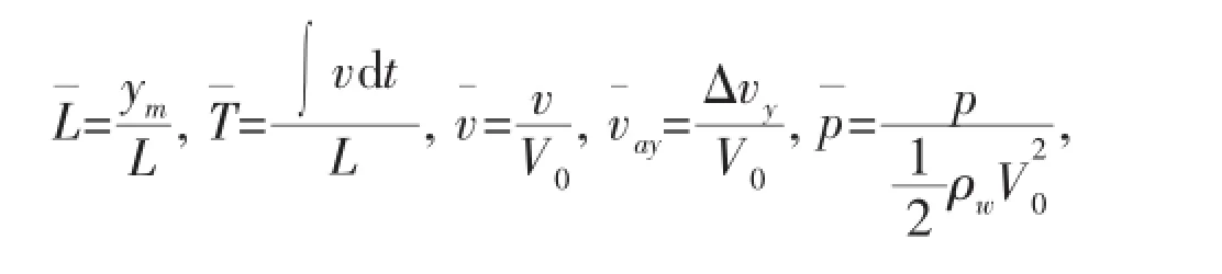
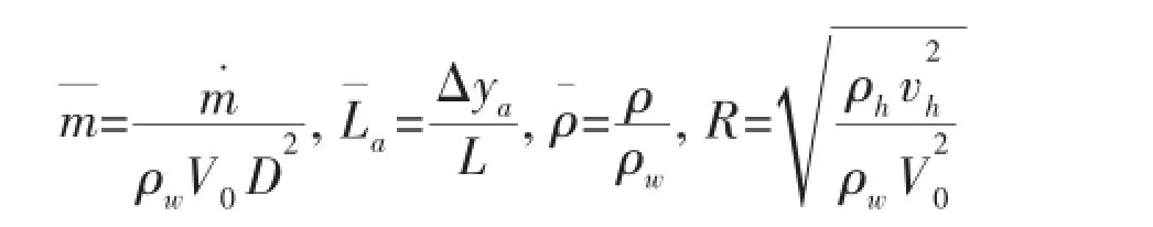
where L,D and V0are the length,diameter and velocity of the vehicle,respectively.ymis the distance from a certain point on the surface of the vehicle to its head.The density of the water phase is ρw.The velocity in y direction of the local coordinate system is△vy,and the axial length of the film is△ya.The mass flow rate of the exhaust is m˙.And ρhand vhare the averaged density and velocity of the air at the exit of the exhaust hole.
1.5 Validation of numerical method
The natural cavitation flow of an axisymmetric body was simulated numerically to verify the reliability of the numerical method in this paper.Fig.4 provides the comparison of the numerical and experimental[20]pressure coefficients on the body surface under different cavitation numbersThe good agreement proves the validity of the numerical method.

Fig.4 Comparison between numerical and experimental data[20]
2 Results and discussion
2.1 Shape features and evolution of pressure-equalizing film
Fig.5 gives the distribution of the phase volume fraction α(α=0 for air phase,α=1.0 for water phase)and streamline on both the surface and symmetry plane of the vehicle under different exhaust angles and different characteristic moments.The streamline is observed in the local coordinate system.It can be seen that the pressure-equalizing film can be divided into the air phase region,the mixed phase region and the rear leakage region.
The air phase region presents an hourglass shape with thick ends and a fine middle.The large front size of the air phase area is due to the rapid expansion of the high-pressure air in the water to generate the air film.The accumulation of air flow to the center line in the middle part of the air phase region results from the fact that the air velocity is higher and the air pressure is lower near the center line than those at the both sides.The large size of the rear of the air phase region is related to the blocking effects of the re-entrant jet.

Fig.5 Distribution of phases volume fraction α and streamline on the surface and the symmetry plane of the vehicle under different characteristic time
The main feature of the mixed phase region is the existence of the re-entrant jet starting from the closure point at the film tail,which is driven by the adverse pressure gradient produced by the high pressure at the closure point and the relatively low pressure inside the film.The re-entrant jet entrains the water outside the film to flow upstream and mixes with the air inside the film,resulting in a large value of α near the center line.When the mixed fluid meets the air that moves downstream at the end point of the re-entrant jet,it flows towards the both sides along the circumferential direction and upwards along the radial direction,and then turns into a downstream movement.The air bypasses that point and flows downstream along with the mixed fluid.The size of the film enlarges as a result of the upstream and downstream flows.With the time increasing,the mixing effect among the downstream mixed fluid and air as well as the water surrounding the air film is more intense,and the distribution of α in the mixed phase region tends to be uniform,thus the mixed phase zones of the adjacent film getclose to each other along the circumferential direction till almost merge.The re-entrant jet is the main feature of the unsteady development of the pressure-equalizing film,whose intensity and region of influence determine the variation of the property of the fluid flowing around the vehicle,and its flow characteristics and flow field structure.It can be seen from Fig.5 that the axial and circumferential dimension of the pressure-equalizing film increase as the exhaust angle γ drops.At,the axial length of the film and the maximum circumferential width increase by about 50%and 35%respectively when the exhaust angle γ increases from 30°to 90°.In other words,when the exhaust angle is smaller,the film advances faster and covers a wider range,which is beneficial to the rapid formation of the film and playing its role in affecting the hydrodynamic characteristics of the underwater vehicle.
When the film tail closes on the surface of the vehicle,a positive pressure gradient comes into being between the high-pressure region near the closure point due to the flow stagnation and the relatively low-pressure area of the water flow field near the vehicle surface after the film tail,which affects the leakage flow around the film tail.With the interaction between the air and the water,part of the air is broken into discrete bubbles from its original continuous state,and the bubbles leak out of the air film along the bottom layer of the film attached to the surface of the vehicle,resulting in the generation of the slightly elongated leakage flow extending to the tail of the underwater vehicle.Besides, the mixed fluid at the outer edge of the film merges with the leakage flow at the film tail.The leakage flow at the film tail is one of the features of the shape of the pressure-equalizing film, which may have an impact on the hydrodynamic characteristics of underwater vehicles in some cases.
2.2 Vortex structure of the pressureequalizing exhaust flow

Fig.6 Distribution of phases volume fraction α and streamline near the exhaust hole
Fig.6 and Fig.7 demonstrate the distribution of the phase volume fraction and streamline on the surface and symmetry plane of the vehicle in the vicinity of the exhaust hole as well as the axial sections downstream of the exhaust hole.The relative coordinates of the axial sections,i.e.y¯secis defined as the ratio between the axial distance of the section from the center of the exhaust hole and the diameter of the exhaust hole.It is obvious that for the case that γ equals to 90°,the interaction between the air and the water makes the air
flow bend quickly,while a distinct water flow stagnation and cross-flow separation occur at the leading edge of the exhaust hole.In the early development of the film(T¯=1.0),the velocity ratio R is only 0.2,so the blocking effect suffered by the water flow is small,and the counterrotating vortex pair in the axial sections,which is caused by the cross-flow separation at the two sides of the jet and the shear effect at the edge of the jet,therefore is not obvious.As time goes on,the value of R increases significantly,thus the blockage of the jet toward the boundary layer of the cross flow becomes stronger.A separation saddle point and the corresponding horseshoe vortex form on the surface at the leading edge of the exhaust hole.The two legs of the horseshoe vortex flow around the jet and then go downstream nearly straightly with a small intensity and size.The shear motion at the jet edge causes the formation of the vortex pair movement around both sides of the jet,and they gradually move away from the vehicle surface, rolling up into the counter-rotating vortex pair.The cross-flow separation vortex in the jet shows a spiral movement along the vertical direction,which means that the vortex flows upwards first,and then flows upstream to the leeward side of the jet,finally it tilts and bends to the same direction as the cross flow and rolls up into the counter-rotating vortex pair.The above discussions show that the involvement and consolidation of the shear-layer vortex pair and the cross-flow separation vortex pair near the trailing edge of the exhaust hole are the main source of the counter-rotating vortex pair and also increase its strength and the scale. As the exhaust angle decreases,the blocking effect of the air reduces significantly,and the cross flow passes through the jet with little disturbance.The vortex motion near the exhaust hole is also weak,and the saddle point and the horseshoe vortex disappear at the leading edge, while the cross-flow separation vortex exists at the trailing edge of the exhaust hole but its strength is small.The distribution of the three-dimensional streamline plotted in Fig.8 also shows the spatial flow field structure in the vicinity of the exhaust hole when the exhaust angle changes.Though the density difference between air and water is large,which leads to a small value of R as well as a small intensity and scale of the vortex resulted from the interaction between the cross flow and the jet,the flow in the vicinity of the exhaust hole still presents strongly unsteady and three-dimensional with complex vortex motion.In particular,the motion of the counter-rotating vortex pair takes the jet far away from the vehicle surface, which enhances the interaction between the air and the water,so the development process of the pressure-equalizing film is affected significantly.Consequently,reducing the strength and the scale of the vortex pair as much as possible is one of the important research contents to enhance the hydrodynamic characteristics of underwater vehicles with the pressure-equalizing exhaust technique.

Fig.7 Distribution of phases volume fraction α and streamline in the axial sections at exhaust hole downstream

Fig.8 Distribution of three-dimensional streamline near the exhaust hole

Fig.9 Distribution of phases volume fraction α and streamline near film tail
Fig.9 illustrates the distribution of the phase volume fraction and streamline near the film tail.It can be seen that the main factors that result in the emergence of the re-entrant jet in the film are the colliding and closing of the water at the film tail on both the symmetrical plane of the film along the circumferential direction and the vehicle surface along the radial direction as well as the resulted high-pressure region.,the closure point at the film tail is a saddle point,which means that the re-entrant jet is caused mainly by the colliding of the water surrounding the film tail along the circumferential direction at this moment.however,the closure point is a reattachment node,which indicates that the colliding along the radial direction has a larger effect on the re-entrant jet.For the sake that the radial momentum of the water is larger,the resulted high pressure and the adverse pressure gradient are also larger,so the re-entrant jet tends to be strong.Corresponding to the re-entrant jet,in the flow field there occurs the large-scale vortex motion,the so-called three-dimensional wall vortices, which presents as a counter-rotating vortex pair structure observed from the circumferential direction or a clockwise-rotating vortex structure from radial direction.In the area covered bythe pressure-equalizing film,the dominant feature of the mixed phase zone that forms a larger proportion of the film is the re-entrant jet.The formation mechanism of the three-dimensional vortex motion resulted from the re-entrant jet plays a significant role in revealing the unsteady development laws of the pressure-equalizing air film.
Based on the above analysis of the vortex structures near and downstream of the exhaust hole and in the flow field of the re-entrant jet at the film tail,Fig.10 plots the streamline patterns of a typical flow field on the local surface of an underwater vehicle with pressure-equalizing exhaust.When the pressure-equalizing air is exhausted into the water vertically,there are 4 saddle points,2 critical nodes,4 spiral nodes and 5 separation lines in the flow field. The saddle point S1is associated with the horseshoe vortex,and the two separation lines L1and L2emanating from the saddle point S1and going downstream straightly after flowing around the jet,represent the path lines of the horseshoe vortex.The saddle point S3downstream of the exhaust hole corresponds to the downstream saddle point occurring in the case of flowing around a rigid cylinder,and the spiral nodes N2and N3exist in the vicinity of the trailing edge of the exhaust hole.This saddle point-spiral node pattern resulted from the shear effect between the cross flow and jet is one of the origins of the kidney type vortex pair.The separation line N3starting from the saddle point S3locates on the symmetrical line all the time till some position (saddle point S4)downstream of the exhaust hole,where it bifurcates and flows towards the symmetrical separation lines L4and L5under the influence of the re-entrant jet.The flow separation structure that dominates the re-entrant jet is the pattern starting from the reattachment node N6at the film tail and ending at the spiral nodes N4and N5within the film,which corresponds to the strong upstream and downstream motion resulted from the closure of the water at the film tail.When the pressure-equalizing air is exhausted into the water at a certain angle,since the blocking effect of the inclined air flow on the cross flow is weak,the saddlepoint and the horseshoe vortex at the leading edge of the exhaust hole disappear,and the crossflow separation at the trailing edge of the exhaust hole embodies a combination pattern of the saddle point S1and separation node N1.The flow pattern at the rear part of the film which corresponds to the re-entrant jet is similar to that in the cases of the vertical exhaust.

Fig.10 Schematic of flow field topological structure on local vehicle surface with pressure-equalizing exhaust
2.3 Distribution of pressure coefficient on vehicle surface
As shown in Fig.11 and Fig.12,the distribution of the pressure coefficient illustrates that the flow field in the vicinity of the exhaust hole and its downstream can be divided into five typical zones:
(1)Upstream high-pressure zone.Under the influence of the stagnation effect of the exhausted air on the water flow and the resulted high pressure upstream propagation,the pressure upstream the exhaust hole increases.As time goes on,the high-pressure region is getting larger,and the pressure rises significantly.
(2)Over expansion-contraction zone.When the high-pressure air is exhausted into the water,the pressure peak occurs at the exhaust hole.The air expands in the water rapidly as a form of air film.When the pressure in the film decreases to the ambient pressure,the film continues to expand due to the inertial effect till its velocity reaches zero and its pressure is lower than the ambient pressure,that is,in the over-expansion state.Thereafter the film starts to shrink and the air pressure inside the film increases under the influence of the ambient pressure till the pressure is larger than the ambient pressure,that is,the over-contraction phenomenon occurs.As time goes by,the process of over expansion-contraction tends to be strong. Since this process occurs in the range from the leading edge of the hole to the position 1.5d away from the trailing edge of the hole,it causes an abrupt change of the local pressure which has a negative effect on the surface load characteristics of the vehicle.
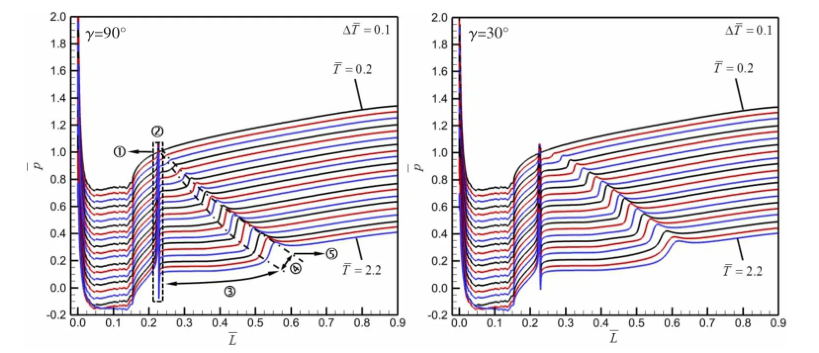
Fig.11 Distribution of surface pressure coefficient along the axis of the vehicle at different characteristic time

Fig.12 Contour of pressure coefficient on vehicle surface and symmetry plane at
(3)Downstream approximate pressure-equalizing zone.After the over expansion-contraction zone,in the film appears the approximate pressure-equalizing zone.According to the above discussion about the features of the film shape,the range of the pressure-equalizing zone basically coincides with the air phase region and the mixed phase region,and its formation mechanism is also related to the flow characteristics of the air phase and the mixed phase.In air phase region,the velocity of the air after over expansion-contraction process is still high,so in the course of its development downstream,the air inside the film maintains its constant pressure by means of deceleration.In the mixed phase region,the mixed fluid maintains its reverse flow velocity by means of reducing the static pressure.The invariant property of the pressure within the air phase region and the mixed phase region is the source of the concept of the pressure-equalizing film.Obviously,the greater the pressure difference between the cavity and the surrounding water is,the higher the exhaust flow rate is,at the same time the faster the air velocity in the air phase zone after the over expansion-contraction process becomes,and the stronger in the mixed phase zone the high pressure and the re-entrant jet caused by the closure of the water at the film tail gets.Also the length of the pressure-equalizing zone in the film becomes longer and its range grows larger.Eventually,the effect of the pressure-equalizing film on the improvement of the hydrodynamic characteristics of the underwater vehicle becomes more obvious.
(4)Strong adverse pressure gradient zone at the film tail.There exists a pressure peak point in this zone.As time goes on,the size of the film gets bigger,and the contraction of the film tail becomes intense,meanwhile the pressure peak increases.The presence of the pressure peak evokes a rapid change of the local pressure on the surface of the submerged body, which is harmful for its load characteristics.
(5)Favorable pressure gradient zone and leakage flow zone after the film tail.Under the effect of the high pressure due to the flow stagnation and the favorable pressure gradient at the film tail,the mixed phase fluid formed by the mixing between the leaking air from the film tail and the water,flows downstream after accelerating and depressurizing.
Besides,since the interaction between the air and the water is weak at a small exhaust angle,which is favorable for more air discharge,the range of the pressure-equalizing zone within the film increases significantly.However,because the expansion-contraction process of the air is slightly stronger,the value of the pressure in the pressure-equalizing zone increases a little.
Fig.13 illustrates the distribution of pressure in the vicinity of the exhaust holes. It can be seen that the existence of the film makes the flow passage of the water between adjacent film decrease,so the water accelerates and depressurizes there,which means that the pressure drop happens in the flow field of water even before the air phase near the exhaust holes coalesces along the circumferential direction.This is beneficial to the formation of the air film with uniform pressure distribution along the circumferential direction on the surface of the underwater vehicle.
2.4 Distribution of some total parameters for pressure-equalizing exhaust
Fig.14 gives the variation of the pressure ratio between the inside and outside cavity,the density of the air inside the cavity,the mass-averaged flow velocity,axial flow velocity and flow angle θαat the exit of the exhaust hole over the non-dimensional time.It can be seen that the air pressure inside the cavity decreases as the air exhausts,while the pressure near the hole exit decreases with the ambient pressure reduction due to the movement of the vehicle,but the ratio of them always increases,leading to the flow velocity,axial flow velocity and flow angle larger and larger.In addition,the density of the air inside the cavity decreases continuously as the air discharges.When the exhaust angle decreases,for the sake that the blocking effect of the cross flow on the air gets weak,the pressure at the hole exit decreases,so the air is easy to be exhausted into the water,resulting in a faster reduction of the air pressure in the cavity and a higher pressure ratio between the inside and outside cavity,thus the flow velocity at the exhaust hole increases consequently.The increase of the flow angle at γ=30°is far less than that at γ=90°,which means that the axial velocity of the air flow increases obviously, thus it is helpful for the formation of the air film along the axial direction.In other words,the design of an inclined pressure-equalizing exhaust hole is beneficial to the rapid and effectivegeneration of the pressure-equalizing film.Fig.15 gives the temporal variation of the mass flow rate of the pressure-equalizing exhaust and the axial film length.The mass flow rate increases with the increase of the pressure ratio between the inside and outside cavity.However,since the air density in the cavity also falls,the increase in the flow rate tends to be rapid at first, then slow,and finally gentle.As the volume of the cavity is constant,when the exhaust angle is small,too much air is exhausted in the early stage,so the increase of the mass flow rate tends to be obviously slow in the later period.

Fig.13 Distribution of phases volume fraction α and pressure coefficient near the exhaust holes

Fig.14 Temporal variation of pressure ratio,density,flow velocity,axial flow velocity and flow angle

Fig.15 Temporal variation of mass flow rate of pressure-equalizing exhaust and axial length of film
3 Conclusions
Based on Reynolds-Averaged Navier-Stokes equations,a numerical simulation of the underwater vertical movement process of an underwater vehicle with pressure-equalizing exhaust is conducted in this paper by using multiphase model,UDF technology and dynamic mesh method.The effects of the exhaust angle on the unsteady development of the pressure-equalizing film,the flow field structure and the flow characteristics of the vehicle are studied.The main conclusions are as follows:
(1)The pressure difference between the inner and outer of the cavity is the driving force of the air exhaust flow.As the exhaust angle decreases,the interaction between the air and the water gets weaker,and the pressure ratio between the inside and outside cavity rises,thus the mass flow rate,flow velocity,flow angle at the exit of the exhaust hole as well as the film length also increase obviously,which is beneficial to the fast formation of the film to improve the hydrodynamic characteristics of the underwater vehicle.
(2)From the point of view of phase,the film can be divided into the air phase region,the mixed phase region and the rear leakage region.It also can be classified into five parts based on the features of the pressure distribution such as the high-pressure zone,the over expansion-contraction zone,the approximate pressure-equalizing zone,the adverse and favorable pressure gradient zones.The pressure-equalizing characteristics is obtained by the rapid reduc-tion in the downstream velocity of the air within the film in the air phase region and the reduction in the upstream velocity of the fluid in the mixed phase region.When the exhaust angle is small,the range of the pressure-equalizing region within the film increases significantly.
(3)When the exhaust angle decreases,the horseshoe vortex,cross-flow separation vortex,and counter-rotating vortex pair in the flow field near the exhaust hole become weaker or even disappear,thus the flow field structure tends to be simple.But the high pressure due to the flow stagnation and the resulted adverse pressure gradient at the closure point of the film tail change little,so the flow field structure here is almost unchanged,characterized by the reentrant jet flow and its induced wall vortex.
(4)As the exhaust angle decreases,the saddle point and the horseshoe vortex related to it disappear gradually at the leading edge of the exhaust hole,meanwhile the cross-flow separation vortex and the counter-rotating vortex pair weaken significantly at the trailing edge of the exhaust hole,but the flow pattern of the saddle-spiral node or reattachment-spiral node that dominates the re-entrant jet keeps unchanged.
[1]Song Jin.Review of active control methods for underwater launching missile[J].Missiles and Space Vehicles,2012(3):26-28.(in Chinese)
[2]Burgdorf O.Hydrodynamics of unsteady underwater launched missile with trailing cavities and cross-flow drag[C].AlAA-87-1319.
[3]Bao Wenchun,Quan Xiaobo,Wei Haipeng.Numerical simulation on the flow dynamics of underwater vehicle launching with exhaust[J].Missiles and Space Vehicles,2014,5:14-18.(in Chinese)
[4]New T H,Lim T T,Luo S C.Elliptic jets in cross-flow[J].Journal of Fluid Mechanics,2003,494:119-140.
[5]Barata J M,Durao D F G.Laser-Doppler measurements of impinging jet flows through a crossflow[J].Experiments in Fluids,2004,36:665-674.
[6]Sau A,Sheu T W H,et al.Three-dimensional simulation of square jets in cross-flow[J].Physical Review E,2004,69:l-20.
[7]Jiang Guoqiang,Ren Xiuwen,Li Wei.Numerical simulation of vorticity dynamics for turbulent jet in crossflow[J].Advances in Water Science,2010,21(3):307-314.(in Chinese)
[8]Kelso K R,Smits A J.Horseshoe vortex systems resulting from the interaction between a laminar boundary layer and a transverse jet[J].Physics of Fluids,1995,7:153-158.
[9]Zhang Yan.Experimental and numerical investigations on the vortical structures of an impinging jet in crossflow[D].Shanghai:Shanghai University,2005.(in Chinese)
[10]Maurel S,Sollied C.A turbulent plane jet impinging nearby and far from a flat plate[J].Experiments in Fluids,2001,31 (6):687-696.
[11]Xiang Min.Numerical research on ventilated cavitating flow for the supercavitating vehicles[D].Beijing:National University of Defense Technology,2011.(in Chinese)
[12]Jin M S,Ha C T,Park W G.Numerical study of ventilated cavitating flows with free surface effects[J].Journal of Mechanical Science and Technology,2013,27(12):3683-3691.
[13]Guo J,Lu C.Pulsation characteristics of ventilated supercavitation on a 2D hydrofoil[J].Journal of Shanghai Jiaotong University(Science),2010,15:423-427.
[14]Zhang G,Yu K P,Zhou J J.Numerical research on ventilated supercavity shape and flow structure in the turning motion [J].Journal of Ship Mechanics,2011,15(12):1335-1343.
[15]Kawanami Y,Kato H,Yamaguchi H,et al.Mechanism and control of cloud cavitation[J].Journal of Fluids Engineering, 1997,119:788-794.
[16]Wang Yiwei,Huang Chenguang,Fang Xin,et al.Characteristics of the re-entry jet in the cloud cavitating flow over a submerged axisymmetric projectile[J].Chinese Journal of Hydrodynamics,2013,A28(1):23-29.(in Chinese)
[17]Duan Lei.Study on characteristics of ventilated cavitating flows around an axisymmetric body[D].Beijing:Beijing Institute of Technology,2014.(in Chinese)
[18]Manninen M,Taivassalo V,Kallio S.On the mixture model for multiphase flow[M].VTT Publications 288,Technical Research Centre of Finland,1996.
[19]Qin Yong.Effect of gas exhausting on hydrodynamic characteristic of underwater vehicle considering wave[D].Harbin Institute of Technology,2014.(in Chinese)
[20]Rouse H,McNown J S.Cavitation and pressure distribution,head forms at zero angle of yaw[R].State University of Iowa Engineering Bulletin 32,No.420,1948.
排气角度对航行体表面等压气膜演化机制及流动特性影响研究
陈浮,马贵辉,俞建阳,姜帅
(哈尔滨工业大学能源科学与工程学院,哈尔滨150001)
等压排气是一种可有效改善航行体绕流流场特性、抑制纵向偏转的流动控制技术。文章数值模拟了带等压排气的航行体水下垂直运动过程,给出了不同排气角度时的排气流量及速度、气膜长度等参数变化规律,分析了排气角度对等压气膜非定常发展过程及航行体绕流流场特性的影响,建立了排气孔附近及其下游流场、气膜尾部回射流场的拓扑结构,探讨了等压气膜的形态特征、演化规律及其降低航行体表面压力的机制,研究结果有助于深入理解等压排气技术改善航行体流体动力学特性的物理本质。
航行体;等压排气流;排气角度;演化机制
TV131.2
A
陈浮(1970-),男,哈尔滨工业大学能源科学与工程学院教授,博士生导师;马贵辉(1990-),男,哈尔滨工业大学能源科学与工程学院博士研究生;俞建阳(1987-),男,哈尔滨工业大学能源科学与工程学院博士研究生;姜帅(1991-),男,哈尔滨工业大学能源科学与工程学院博士研究生。
TV131.2 < class="emphasis_bold">Document code:A
A
10.3969/j.issn.1007-7294.2016.12.001
1007-7294(2016)12-1495-18
Received date:2016-08-05
Foundation item:Supported by the Foundation for Innovative Research Groups of the National Natural Science Foundation of China(Grant No.51421063)
Biography:CHEN Fu(1970-),male,professor/tutor of Harbin Institute of Technology,E-mail:chenfu@hit.edu.cn; MA Gui-hui(1990-),male,Ph.D.student.
猜你喜欢
杂志排行

船舶力学的其它文章
- Study on a 3D Time-domain Method to Predict Parametric Rolling of a Ship in Regular Head Seas
- Dynamics and Experiments of a Laboratorial Underwater Glider
- Prediction of Ship-Ship Interaction Forces in Shallow Water Using a High-order Panel Method
- Numerical Evaluation on Dynamic Positioning for Semisubmersible Platform based on Backstepping Control
- Preliminary Evaluation of Maraging Steels on Its Application to Full Ocean Depth Manned Cabin
- Study on the Connector Loads Characteristics of a Very Large Floating Structure in the Impact Accident