Dynamics and Experiments of a Laboratorial Underwater Glider
2016-05-16CAOJunliangCAOJunjunZHAOBaoqiangYAOBaohengLIANLian
CAO Jun-liang,CAO Jun-jun,ZHAO Bao-qiang,YAO Bao-heng,3,LIAN Lian,3
(1.State Key Laboratory of Ocean Engineering;Institute of Oceanology,Shanghai Jiao Tong University, Shanghai 200240;2.Qingdao Collaborative Innovation Center of Marine Science and Technology, Qingdao 266000,China;3.China Ship Development and Design Center,Wuhan 430064,China)
Dynamics and Experiments of a Laboratorial Underwater Glider
CAO Jun-liang1,CAO Jun-jun1,ZHAO Bao-qiang2,YAO Bao-heng1,3,LIAN Lian1,3
(1.State Key Laboratory of Ocean Engineering;Institute of Oceanology,Shanghai Jiao Tong University, Shanghai 200240;2.Qingdao Collaborative Innovation Center of Marine Science and Technology, Qingdao 266000,China;3.China Ship Development and Design Center,Wuhan 430064,China)
In this paper,the design,implementation,and experiments of a weight-varied underwater are presented.The realization of the buoyancy engine is mainly accomplished by a unidirectional water pump and a three position five-way solenoid valve.The glider is designed to operate within 30 meters deep down to the water surface,and the detailed design process is introduced.The glider’s equation of motion and dynamic features are presented and the steady-state solution is analyzed.The hydrodynamic coefficients are also calculated by using Computational Fluid Dynamics(CFD)method.Simulation and experimental results show the reliability and utility of the underwater glider.
underwater glider;buoyancy engine;weight-varied;dynamic;CFD
0 Introduction
The interest in monitoring underwater environments by using conventional autonomous underwater vehicles(AUVs)and underwater gliders is growing in recent years.The practical applications include patrolling seaports,tracking oil spills,and monitoring harmful algal blooms[1]. The vehicle needs to be capable of high efficiency to maintain sustainable operating time duration,and meanwhile high maneuverability to negotiate with versatile environments.Underwater glider is a new dynamic underwater observation platform,known for its great energy-efficiency and long-duration operation in oceanographic applications[2],which utilizes its net buoyancy to achieve motion without any additional propulsion system and alters its center of gravity to adjust attitude.
Legacy underwater glider is driven by the change of net buoyancy which is mostly achieved by adjusting its volume of displacement and meanwhile its weight is remain unchanged such as Seaglider[3],Spray[4],and Slocum[5].The hybrid-driven underwater glider is a novel research area in recent years,for instance,Folaga[6]has a diving actuation mechanism as an oceanographic glider and autonomous surface navigation capabilities as self-propelled AUVs;PETRAL[7]and Sterne[8]are designed with both ballast control and a thruster.Other driven solutions have been used:the ALBAC design uses a drop weight to drive the glider in a single dive cycle between deployment and recovery from ship[9];SML glider[1]is a miniaturized underwater combines the desirable features of both an underwater glider and robotic fish;Wave glider[10]is an unmanned maritime vehicle(UMV)unique in its ability to harness ocean wave energy for platform propulsion.
In this paper,the change of net buoyancy is achieved by adjusting the body weight while the volume of displacement is remain unchanged.For conventional bidirectional water pumps, either the volume is oversized for underwater glider or the flow rate is dilatory for the buoyancy adjustment process.The mechanism in this paper has overcome these problems and verified through experiments.This kind of underwater glider is easier to operate than conventional gliders,suitable for fundamental studies and laboratorial experiments.Also,the hydrodynamic model and mathematic model have been analyzed to obtain the necessary parameters which will be used in the simulating process.The experimental results have demonstrated the reliability and utility of the glider.
This paper is organized as follow:the glider description and the design process are introduced in Chap.1;the establishments and analysis of mathematic model as well as the hydrodynamic model of the underwater glider is given in Chap.2;the experiment results comparing with simulation results are shown in Chap.3;finally the conclusions and future works are drawn in Chap.4.
1 Glider description
As a demonstrated underwater glider in this study,it is designed to work 30 meters deep under the water surface.Some of the main design parameters are listed in Tab.1.The pressure hull of the underwater glider consists of the front pod,cylindrical hull and the rear pod.The material we choose is polymethylmethacrylate (PMMA),which is a transparent organic compound capable of considerable compression strength and appropriate for the experimental underwater glider.The front pod and rear pod are designed in streamlined shape to optimize the lift-drag ratio.The aspect ratio of the wing is 4.0,while the taper of the wing is 3.0,and it has a sweepback of 18 degrees so that the glider is in best working condition.
Be distinguished from other underwater gliders in the world,the glider in this study adjusts its net buoyancy by absorbing and draining ambient water.Compared with other volumevaried underwater gliders,this buoyancy engine(Fig.1)is much simple in processing and easyto control.Besides,other underwater gliders usually must be capable of the ability to monitor the flow rate precisely,while mechanism in this paper is simplified by controlling the working time of the pump.

Tab.1 Main parameters of the glider
The greatest difficulty in the design process is to control the size of water pump and guarantee the pumping rate at the meantime.For conventional bidirectional water pump,either the volume is oversized for underwater glider or the flow rate is dilatory for the buoyancy adjustment process.To deal with these problems,a unidirectional water pump and a three position five-way solenoid valve is used.The function of the three position five-way solenoid valve is to change both the water inlet and outlet simultaneously.A small capsule is set in the mechanism as an accumulator since the switch of the valve needs a start-up pressure.
The same as most underwater gliders,changing the center of gravity is achieved by translating an internal moving mass(including the battery),which is usually weighted 15%-20%of the whole glider.More translating distance will be needed if the moving mass is lighter,which will extend the length of the glider.Otherwise,if the weight of moving mass is too heavy,the attitude adjustment will be sensitive excessively,causing the underwater glider be difficult to control.The movement of the mass is accomplished by a high efficiency and high accuracy linear actuator for the pitch system,the position of the moving mass is measured by the rotation of the stepper motor,which is convenient to control and operate precisely.
The roll actuator is utilized another single mass for the sake of convenient,which is designed in a half-cylinder shape so that the center of gravity is slightly below the centerline of the glider.It is also driven by high efficiency and high accuracy stepper motor connected with worm gears to achieve the rotation.
Several sensors are equipped on the underwater glider to collect data and monitor the operating status.A pressure sensor and a temperature sensor are installed at the front cover to record the operating depth and ambient temperature;an attitude sensor is set in the electronic bay to monitor and provide the attitude angles and angular accelerations for the control algorithm;a flowmeter is concatenated with the water bladder monitoring the working status of the buoyancy engine.
2 Modeling
2.1 Mathematic model

Fig.1 Buoyancy engine
In this paper,the underwater glider is modeled as a rigid-body system,with an externalforce and moment exerted by an internal movable mass.The sketch map of the glider in the body-fixed reference frame denoted as Oxbybzbis shown in Fig.2;the origin O is located at the geometric center,which will be the point of application for the buoyancy force.The Oxbaxis is along with the body’s longitudinal axis pointing to the head;the Oybaxis is perpendicular to the Oxbaxis and pointing to the right wing;the Ozbaxis is perpendicular to the other axes and pointing downwards.The pitch angle θ is defined as the angle between Oxband horizontal plane;while the angle of attack α is defined as the angle between the velocity and Oxb.v=[v1,0,v3]stands for the translational velocity of the glider,expressed in the body-fixed reference frame.
The longitudinal equations of motion are adopted from the reference[11],which are restrict in the vertical plane.The definitions of all variables appearing in equations of motion are listed in Tab.2.

Fig.2 The glider’s reference frames

Tab.2 Definitions of all variables appearing in longitudinal equations of motion of the underwater glider

where

During the steady state,the angular velocity becomes zero while the velocity remains stable.The control variables rpand mbare constants as well,means that the position of the movable mass is fixed and the pumping rate is zero.The following equations are the steady state of the equations of motion,solutions to these equations will provide the steady gliding path.
where Ld,Ddand MDL2dare the hydrodynamic forces and moment in the steady state,which are generally dependent on the angle of attack and the velocity magnitude.The expressions can be presented by:
where Cd,Cland Cmare the coefficients of drag,lift,and moment;KD0,KD,KL0,KL,KM0,and KMare constant hydrodynamic parameters;αdis the angle of attack at steady state.
Therefore the state value of the glider parameters can be calculated:

where ξdis the desired gliding angle and Vdis the desired gliding speed.
2.2 Hydrodynamic model
Estimation of the hydrodynamic parameters of the underwater glider is a challenging task because when the velocity and the angle of attack are sufficiently high,non-linear dynamics become dominant[12].Thus,it is necessary to obtain a large number of hydrodynamic lift and dragcoefficients to describe the total hydrodynamic forces on the glider.In order to analyze and estimate the hydrodynamic properties of the glider,we have used Computational Fluid Dynamics method(CFD).The ICEMTMand FluentTMsoftware are used for CFD analysis.ICEMTMis used to discretize the flow domain on to a finite set of the control volume;and FluentTMis to solve the flow in the domain.In the CFD analysis,the drag,lift force and moment coefficients are dependent on the density and velocity of the fluid,as well as on the geometry of the glider and its orientation.Thus,the drag,lift,and moment force coefficient are formulated as follows:

where L is the lift force,D is the drag force,M is the moment acting on the glider body,ρ is the fluid density,Aris the reference area,and c0is the reference length(chord length).In this study,the fluid is chosen as water-liquid whose density is 998.2 kg/m3.
The CFD analysis is based on structured hexahedron cells as the meshing grid as shown in Fig.3.In addition,the k-epsilon RNG turbulence model with a Reynolds number greater than 106is used as the model,Figs.4-7 show the snap shot of the contours of static pressure, contours of dynamic pressure,velocity vectors for the glider,and velocity vectors for the propeller,respectively,at a 6°angle of attack with a velocity of 0.5 m/s.

Fig.3 The computational domain and grid of the glider
The static pressure contour in Fig.4 indicates the pressure distribution around the glider. It shows that the highest pressure is at the tip of the glider’s front pod,due to the impact between the fluid and the glider’s front pod.The static pressure for the rest of the glider surface is lower,due to the smooth flow between the fluid and the cylindrical hull.The contours of the dynamic pressure in Fig.5 shows the pressure distribution around the glider when the glidermoves through the fluid.This contour shows that the pressure is low at the glider body except some small areas of higher pressure located at the front pod,the wing,and the tail,due to the streamline of the glider’s shape.

Fig.4 Static pressure contour of the underwater glider

Fig.5 Dynamic pressure contour of the underwater glider
Fig.6 show the velocity vectors of the underwater glider.

Fig.6 Velocity vectors of the underwater glider
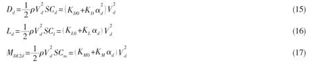
The lift,drag and moment coefficients of the glider have been analyzed for various angles of attack and velocities.The angle of attack(Aoa)is every 2°between 0°and 10°,and the velocities is 0.3 m/s,0.4 m/s,0.5 m/s,0.6 m/s,and 0.7 m/s.Fig.7 and Fig.8 show the lift and drag coefficient of the glider over the angle of attack and velocity,respectively.The graphs show that the lift and drag force coefficient both increase when the angle of attack is increased, while the lift coefficients and drag coefficients will decrease while the velocity increases.Fig.9 shows the lift-drag ratio of the glider,which indicates that the largest lift-drag ratio occurs at 4°no matter what the velocity is,where the glider in this study has the best performance.

Fig.7 Lift force coefficient over the angle of attack of the glider
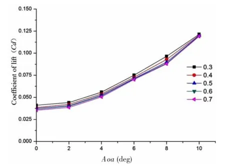
Fig.8 Drag force coefficient over the angle of attack of the glider
The coefficient of moment over the angle of attack is presented in Fig.10,which shows that the coefficients increase when the angle of attack increases;while the coefficients decreases when the velocity increases.

Fig.9 Lift-drag ratio over the angle of attack of the glider
Fig.10 Coefficient of moment over the angle of attack of the glider
3 Simulation and experiment results
3.1 Glider simulation
According to the calculating results of the CFD model of the glider,the hydrodynamic coefficients can be estimated as follows:KD0=4 N(s/m)2,KD=238 N(s/ m)2,KL0=0,KL=265 N(s/m)2,KM0=0,KM=-328 Nm(s/ m)2.Thus the steady gliding path under different desired velocities and pitch angles can be simulated as shown in Tab.2.
The simulation results show that the angle of attack at steady state is independent from gliding velocity,however,it decreases while the gliding angle increases as shown in Fig.11.

Fig.11 Angle of attack with respect to gliding angle

Tab.3 Steady state gliding configurations
We have used the MATLAB software to simulate the glider’s equations of motion;Fig.12 shows the main gliding parameters for one period under the condition of V=0.3 m/s and pitch angle of 12.2 degrees.The simu-lation results indicate that small vibration occurs while the glider is switching from decline to ascend,besides, the glider performs well in simulation.
3.2 Experimental results
Underwater glider experiments have been conducted in a 6-meterdeep water pool to validate the model. We set the initial net buoyancy negatively and the linear actuator position to desired values.Then the glider is released from the water surface then driven into steady motion as shown in Fig.13.The programmed time period, the water pump drains water to the water pool which allows the glider ascends back to surface.
Since the depth sensor is installed at the front cover of the glider, the measured depth is slightly deviated from the actual value.Therefore,we use the following equations to revise the depth:
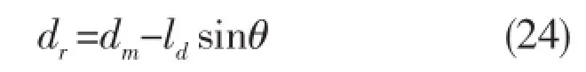
where dris the revised depth,dmis the measured depth reading from the sensor,ldis the estimated distance between the depth sensor and the center of gravity of the glider.
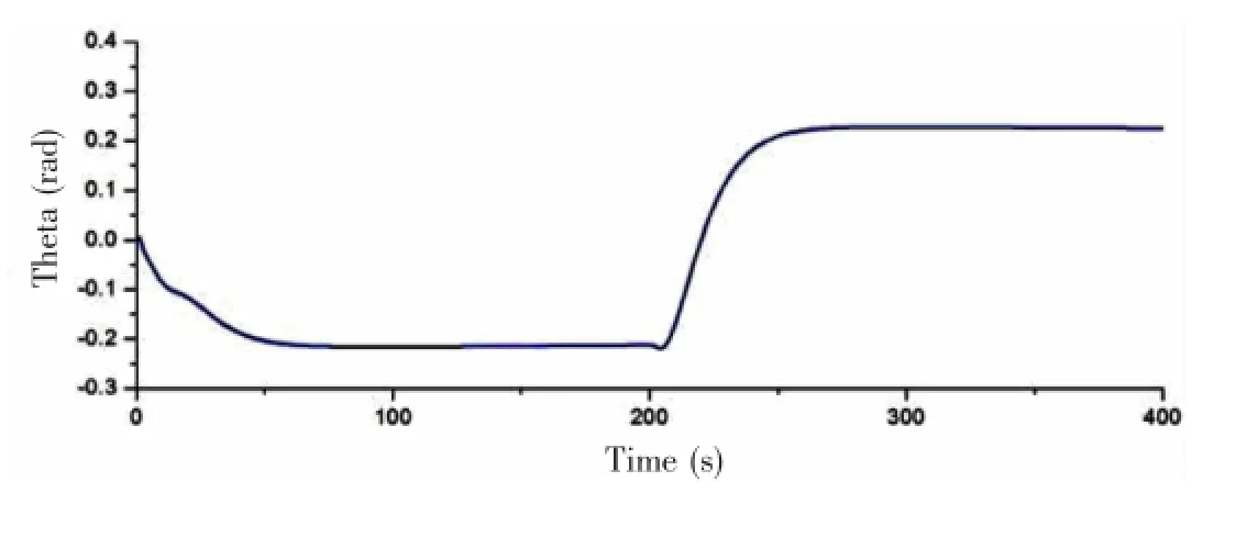
Fig.14 is the experimental depth with respect to gliding time while Fig.15 is the gliding angle monitoring.The glider behaves a slow diving speed at the beginning due to the slow pumping rate; after about 20 seconds the glider was driven into steady motion and the diving speed and gliding angle perform stable. The experimental data show that the glid-er operates smoothly in the water,and suits well as simulated.

Fig.12 Behavior in the longitudinal motion

Fig.13 Gliding experiment in water pool

Fig.14 Experimental depth with respect to time
4 Conclusion
In this paper,we presented the design, implementation,and experiment of a weightvaried underwater glider.The design was carried out systematically with a steadystate model for the glider,and a hydrodynamic model was built based on CFD theory.The prototype was successfully demonstrated by simulating in MATLAB software after calculating the hydrodynamic coefficients and experiments in the indoor water pool.
For future work,we will optimize the profile of the hull and wings,modify the linear actuator as well as the buoyancy engine,and do more reliable experiments in deeper water outdoor.Studying the feedback control algorithm in the longitudinal motion and spiral motion in 6 DOFs is another challenging work which affects the performance of glider significantly.

Fig.15 Glide angle with respect to time
[1]Zhang F,Thon J,Thon C,Tan X.Miniature underwater glider:Design and experimental results[Z].2014.
[2]Rudnick D L,Davis R E,Eriksen C C,Fratantoni D M,Perry M J.Underwater gliders for ocean research[J].Marine Technology Society Journal,2004,38:73-84.
[3]Eriksen C C,Osse T J,Light R D,Wen T,Lehman T W,Sabin P L,et al.Seaglider:A long-range autonomous underwater vehicle for oceanographic research[J].Oceanic Engineering,2001,26:424-36.
[4]Sherman J,Davis R,Owens W,Valdes J.The autonomous underwater glider‘Spray’[J].Oceanic Engineering,2001,26: 437-46.
[5]Webb D C,Simonetti P J,Jones C P.SLOCUM:An underwater glider propelled by environmental energy[J].Oceanic Engineering,2001,26:447-52.
[6]Alvarez A,Caffaz A,Caiti A,Casalino G,Gualdesi L,Turetta A,et al.Folaga:A low-cost autonomous underwater vehicle combining glider and AUV capabilities[J].Ocean Engineering,2009,36:24-38.
[7]Wang S X,Sun X J,Wang Y H,Wu J G,Wang X M.Dynamic modeling and motion simulation for a winged hybriddriven underwater glider[J].China Ocean Engineering,2011,25:97-112.
[8]Graver J G.Underwater gliders:Dynamics,control and design[M].Citeseer,2005.
[9]Kawaguchi K,Tomoda Y,Kobayashi H,Ura T.Development and sea trials of a shuttle type AUV‘ALBAC’[C].International Symposium on Unmanned Untethered Submersible Technology:University of New Hampshire-Marine Systems, 1993:7.
[10]Manley J,Willcox S.The wave glider:A persistent platform for ocean science[J].OCEANS 2010 IEEE-Sydney:IEEE, 2010:1-5.
[11]Bhatta P.Nonlinear stability and control of gliding vehicles[M].Princeton:Princeton University,2004.
[12]Isa K,Arshad M,Ishak S.A hybrid-driven underwater glider model,hydrodynamics estimation,and an analysis of the motion control[J].Ocean Engineering,2014,81:111-29.
试验型水下滑翔机的动力学分析及实验
曹俊亮1,曹军军1,赵宝强2,姚宝恒1,3,连琏1,3
(1.上海交通大学海洋工程国家重点实验室,上海200240;2.海洋科学与技术青岛协同创新中心,青岛266000;3.中国舰船研究设计中心,武汉430064)
水下滑翔机是一种新型的无推进装置的水下运载器,它是由净浮力来驱动的,同时通过内部的直线驱动器来改变重心的位置以实现姿态的调节。对于大多数水下滑翔机,浮力机构是通过改变自身排水体积来实现的,文中介绍了一种变重量的水下滑翔机的设计、动力学分析以及实验过程,该浮力调节机构主要由单向水泵和三位五通电磁阀组成,最大下潜深度为30米。文中介绍了水下滑翔机的运动方程和动力学特性,并且给出了在稳定时刻的解,并且通过计算流体力学的方法对水下滑翔机的水动力特性进行了分析。仿真和实验结果证明了该水下滑翔机的可靠性及实用性。
水下滑翔机;浮力调节机构;变质量;动力学;计算流体力学
U674.941
A
曹俊亮(1989-),男,上海交通大学船舶海洋与建筑工程学院博士研究生;曹军军(1989-),男,上海交通大学船舶海洋与建筑工程学院博士研究生;赵宝强(1990-),男,中国舰船研究设计中心助理工程师;姚宝恒(1975-),男,上海交通大学副教授;连琏(1962-),女,上海交通大学教授,博士生导师。
U674.941 < class="emphasis_bold">Document code:A
A
10.3969/j.issn.1007-7294.2016.12.003
1007-7294(2016)12-1523-12
Received date:2016-06-25
Foundation item:The Research Fund for Science and Technology Commission of Shanghai Municipality (STCSM)(No.13dz1204600)
Biography:CAO Jun-liang(1989-),male,Ph.D.candidate of Shanghai Jiao Tong University,E-mail: xavier.cao@sjtu.edu.cn;LIAN Lian(1962-),female,professor/tutor of Shanghai Jiao Tong University,E-mail:llian@sjtu.edu.cn.
猜你喜欢
杂志排行

船舶力学的其它文章
- Effect of Exhaust Angle on Evolutionary and Flow Characteristics of Pressure-equalizing Film on Surface of Underwater Vehicle
- Study on a 3D Time-domain Method to Predict Parametric Rolling of a Ship in Regular Head Seas
- Prediction of Ship-Ship Interaction Forces in Shallow Water Using a High-order Panel Method
- Numerical Evaluation on Dynamic Positioning for Semisubmersible Platform based on Backstepping Control
- Preliminary Evaluation of Maraging Steels on Its Application to Full Ocean Depth Manned Cabin
- Study on the Connector Loads Characteristics of a Very Large Floating Structure in the Impact Accident