拜尔模式的可编程逻辑器件实现
2016-04-25琚新刚
琚新刚
(河南教育学院 电路与系统重点学科组,河南 郑州 450046)
拜尔模式的可编程逻辑器件实现
琚新刚
(河南教育学院 电路与系统重点学科组,河南 郑州 450046)
摘要:在数字视频接口的设计中,当信道条件相同时,远距离传输的性能要求使得高数据率的实现难度剧增,为此,常采用数据压缩算法,减小待传输的数据量,降低数据率.提出在可编程逻辑器件上,设计一个状态机,将拜尔模式应用于数字视频接口中,实现数据压缩,简捷易行.经硬件仿真验证,该方案可以将数据率降低为原来的近1/3.
关键词:拜尔模式;数字视频接口;数据压缩;状态机;可编程逻辑器件
0引言
视频信号传输的速率与距离是互相限制的,在远距离传输时,信号衰减严重,加中继器,或者采用高速器件和专用电缆,都将大大增加接口系统的成本.所以在显示质量要求允许的情况下,采用先将信号解码,之后进行图像压缩,降低数据率,最后由以太网传送的方式发送,具有实用价值.可编程逻辑器件在数据处理中,独具快速并行的特点,在数据压缩等高速率要求的系统中,更具独特的优越性.
1拜尔模式原理
彩色数字图像的每个像素对应了红、绿、蓝3种颜色的灰度值,如果这3个灰度值分别用8位二进制数码表示,则其表示的图像是24位图像.放之视频,以传输来自DVI(Digital Visual Interface,数字视频接口)的1 024×768@60 Hz、24位颜色的数字视频信号为例,在无压缩的情况下,考虑到行、场消隐时间,要求数据传输速率将高于
1 024×768×24×60=1 132 462 080 bps.
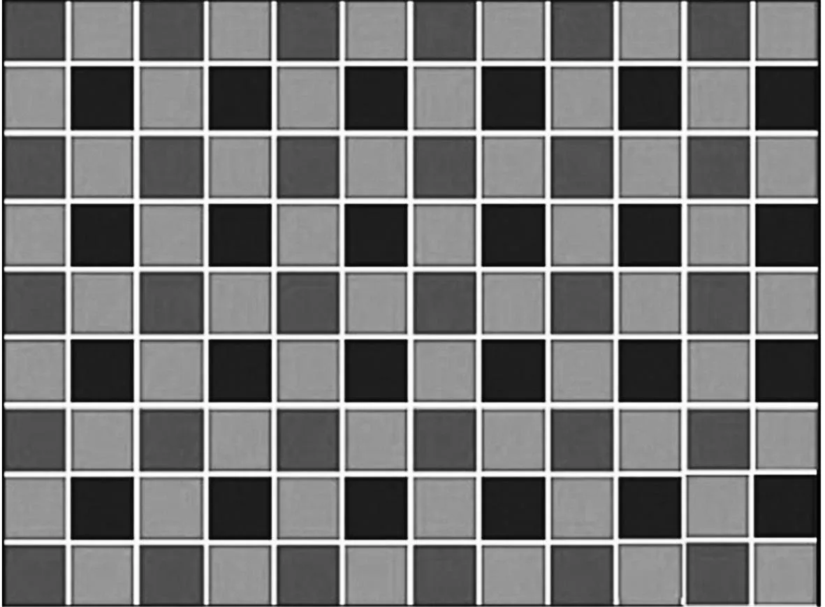
图1 拜尔模式Fig.1 Bayer pattern
为降低数据传输速率,在传送像素灰度值时,只取每个像素的一种颜色灰度值,所取颜色按像素位置进行轮换.如图1所示.在第一行中,按交替规律只取每个像素的红色或绿色灰度值,而在邻近的下一行则取每个像素的绿色或蓝色灰度值.结果是:每帧图像中,被记录下绿色灰度值的像素数为红色和蓝色像素数的和(这样做的原因是人眼对绿色色谱更敏感[1],故而尽量多地保留原来图像的绿色灰度值).
将来图像重构时,各像素所缺的另外两个颜色的灰度值可由相邻的像素获得.获得的方法可采取各种插值算法,最直接的是由相邻的两个不同像素复制.拜尔模式恢复效果已得到验证,尤其用于视频时,效果较为理想[2].同时显见,拜尔模式将数据率降为原来的1/3.
2拜尔模式的硬件实现[3-4]
根据拜尔模式的原理,可以用一个状态机来实现该电路,其电路模型与原理模块如图2所示.
该状态机模型和顶层模块由以下状态机描述文件生成,其构造体包括两个进程:
library IEEE;
use IEEE.STD_LOGIC_1164.ALL;
entity ber is
port(
reset : in std_logic;
clk : in std_logic;
state_inputs: in std_logic_vector(1 downto 0);
R : in std_logic_vector(7 downto 0);
G : in std_logic_vector(7 downto 0);
B : in std_logic_vector(7 downto 0);
output : out std_logic_vector(7 downto 0)
);
end entity ber;
architecture Behav of ber is
type state is (s0,s1,s2);
signal current_state, next_state : state;
signal outs:std_logic_vector(7 downto 0);
begin
reg:process(reset,clk)
begin
if(reset=′1′) then
current_state<= s0;
elsif clk=′1′and clk′event then
current_state<= next_state;
end if;
end process;
com:process(current_state, state_inputs)
begin
case current_state is
……
end case;
end process com;
output<=outs;
end behav;
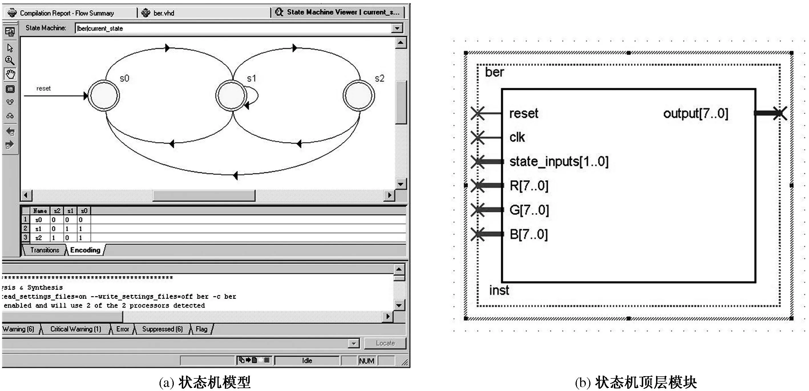
图2拜尔模块
Fig.2Bayer module
3仿真结果分析
在Quartus II硬件设计平台上,对设计的电路进行时序仿真,结果如图3所示,所设计的状态机模块可以按照拜尔模式正确输出数据.
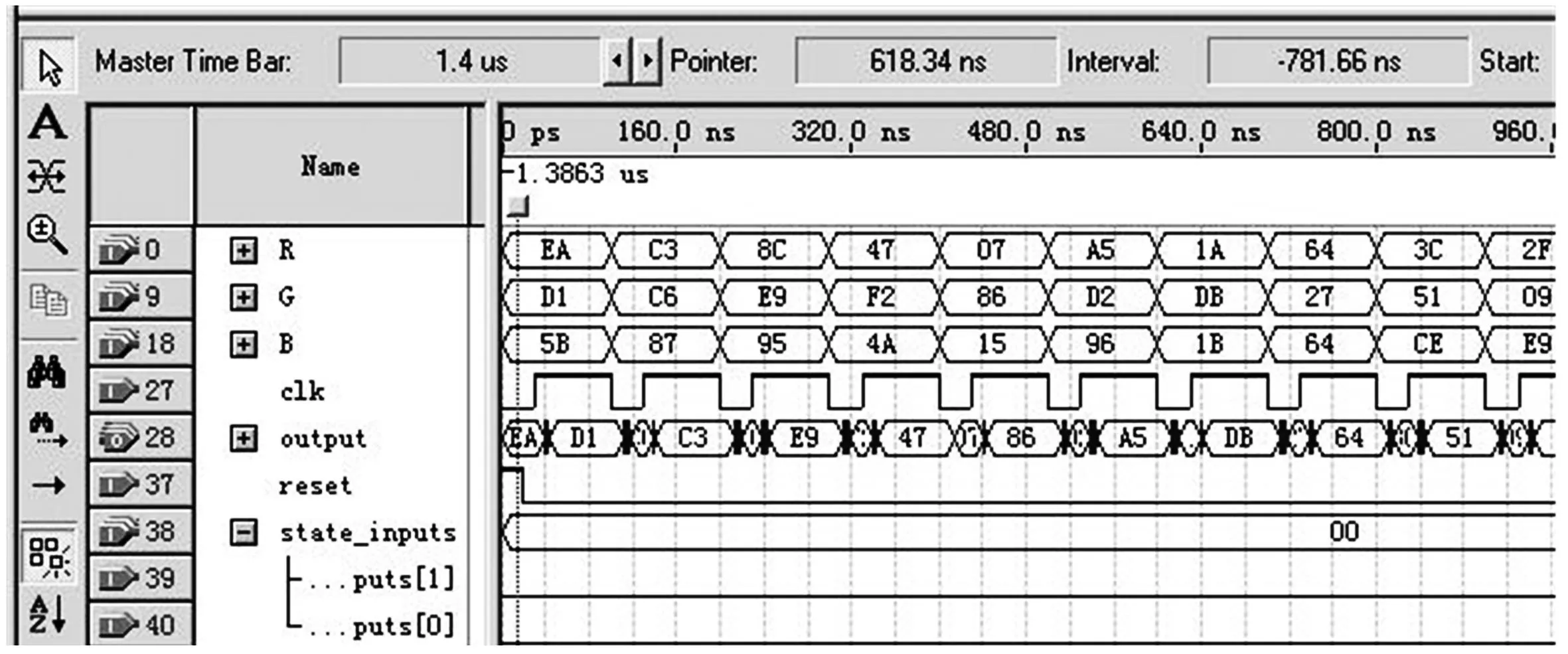
图3时序仿真结果
Fig.3Timing Simulation Results
参考文献
[1]威尔逊.FPGA设计实战[M].杜生海,译.北京:人民邮电出版社,2009:34-36.
[2]The Imaging Source Europe GmbH.彩色CCD相机工作原理介绍[EB/OL]. 2008-03-28[2015-10-12].http://www.opticsky.cn/read-htm-tid-22111-page-e-fpage-5.html.
[3]崔丽杰,张彦军,刘文怡.基于FPGA和DSP的图像压缩系统设计[J].计算机测量与控制,2014(10):3423-3425.
[4]夏金军.应用FPGA的高速数据采集的设计与实现[D].西安:西安电子科技大学,2009.
Realization of Bayer Pattern in Programmable Logic Device
JU Xingang
(GroupofCircuitsandSystemsKeyDisciplines,HenanInstituteofEducation,Zhengzhou450046,China)
Abstract:When designing digital visual interface, in the same channel conditions, the realization of high transfer data is more difficult by performance requirements for long-distance transmission. Therefore, the data compression algorithm is often used to reduce the amount and transfer rate of data to be transmitted. A Bayer pattern state machine in the digital visual interface is designed in a programmable logic device, which can achieve data compression simply and easily. The hardware simulation shows the program data transfer rate can be reduced to nearly one-third of the original.
Key words:Bayer pattern; digital visual interface; data compression; state machine; programmable logic device
中图分类号:TN6
文献标志码:A
文章编号:1007-0834(2016)01-0010-03
doi:10.3969/j.issn.1007-0834.2016.01.003
作者简介:琚新刚(1973—),男,河南教育学院电路与系统重点学科组副教授,主要研究方向:信号处理与EDA技术.
基金项目:河南省科技攻关重点项目(142102210422)
收稿日期:2015-12-24