Switched visual servo control of nonholonomic mobile robots with field-of-view constraints based on homography
2015-12-06BingxiJIAShanLIU
Bingxi JIA,Shan LIU
College of Control Science and Engineering,Zhejiang University,Hangzhou Zhejiang 310027,China
Received 18 May 2014;revised 14 July 2015;accepted 23 July 2015
Switched visual servo control of nonholonomic mobile robots with field-of-view constraints based on homography
Bingxi JIA,Shan LIU†
College of Control Science and Engineering,Zhejiang University,Hangzhou Zhejiang 310027,China
Received 18 May 2014;revised 14 July 2015;accepted 23 July 2015
This paper presents a novel scheme for visual servoing of a nonholonomic mobile robot equipped with a monocular camera in consideration of field-of-view(FOV)constraints.In order to loosen the FOV constraints,the system states are expressed by the homography between the current frame and the key frame so that the target is not necessarily to be always visible in the control process.A switched visual controller is designed to deal with the nonholonomic constraints.Moreover,an iteration strategy is used to eliminate errors caused by the parameter uncertainty.The stablity and robustness of the proposed scheme are guaranteed by theoretical analysis.Compared to conventional schemes,the proposed approach has the following advantages:1)a better path in Cartesian space can be achieved owing to the loosening of FOV constraints;2)the iteration strategy ensures the robustness to parameter uncertainty;3)when used in landmark-based navigation,it needs much sparser and simpler landmarks than those localization-based approaches need.Simulation results demonstrate the effectiveness of the proposed method.
Homography-based,key-frame strategy,field-of-view constraints,nonholonomic mobile robot
DOI 10.1007/s11768-015-4068-8
1 Introduction
Mobile robotic systems are widely used in different areas during recent years,as the most important function,vision-based control has been widely studied in the past decades,a recent survey is[1].From the perspective of controller design,visual navigation methods can be divided into “position-based”and “imagebased”.Position-based approaches regulate the robot to follow a path defined in Cartesian space,with the help of multiple sensors such as GPS,compass and visionbased positioning systems based on landmarks.In such systems,vision systems are used as position measuring instruments,and conventional path following control strategies can be employed[2,3].They are good at longrange navigation with low precision,while they couldbe quite complex especially when robot and landmark positions have to be estimated simultaneously during the exploration of an unknown environment(SLAM:simultaneous localization and mapping[4]).Image-based approaches,whose trajectories are given by a set of images captured along the desired path,are anotherkind of popular approaches.Traditional image-based methods are based on the coordinates of feature points extracted from the images,which may suffer from image noise and partial occlusion[1].To achieve better robustness to image noise and partial occlusion,a good choice is to design the visual servo system based on two-view geometry[5],such as epipolar geometry and homography.Epipolar-based methods[6,7]exploit the epipolar geometry defined by the current and desired views,but this modelis ill conditioned forplanarviews and is problematic with short baseline.Another effective approach is homography-based[8],which exploit the homography between the current and desired views.Early researches usually use the 3D reconstruction information from the homography decomposition[5].Generally,in the decomposition process,foursolutions are generated and an initial guess of the normal vector of the plane is needed to determine the unique one.[9]proposed a control strategy that directly uses the specific characteristics of the homography matrix elements,without the need of 3D reconstruction.
In image-based visual servoing,a typical problem is to deal with the field-of-view constraints of the camera[10],i.e.,the target must be visible in the camera.One way to solve this problem is to combine trajectory planning and tracking[11,12],when successful,it ensures an optimal trajectory in Cartesian space and the visibility of the target.Researchers studied the optimal path for a mobile robot with nonholonomic and field-ofview constraints[13,14],and switch-based methods are proposed to follow the planned path[9].Besides,there are some methods that use advanced control laws taking into account constraints explicitly,such as LMI[15]and predictive control[16].For a deeper discussion on the field-of-view constraints,readers can refer to[1].
In this paper,we proposed a novel framework of image-based visual servoing for nonholonomic mobile robots with field-of-view and nonholonomic constraints.In the proposed approach,the field-of-view constraints are loosened by the key frame strategy.System states are expressed with respect to the key frames instead of the target frame,and they are estimated incrementally from the key frames,without the need of feature point matching with the target frame.As a result,the target object only needs to be visible when the robot reaches key frames,and is not necessarily to be always visible in the control process.Considering the nonholonomic constraints,a switched controller is used to achieve a shortest path control,as show in Fig.1.Compared to conventional methods using a T-curve path[17],a better path in Cartesian space can be achieved.Besides,if the parameter error exists,an iteration strategy is used to eliminate the system error to zero.
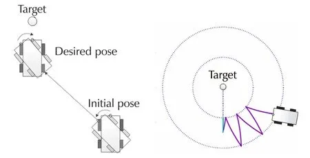
Fig.1 Visual servoing task with field-of view constraints(left:the proposed method,right:the conventional method).
2 Problem formulation and system architecture
The nonholonomic mobile robot considered in this paper is a differential-driven robot moving on the ground,as shown in Fig.2.A down looking monocular camera is mounted at the head of the robot,which is a general case.The visual servoing task is that,given the target image,the robot is regulated to the desired pose where the captured image matches the target image best.
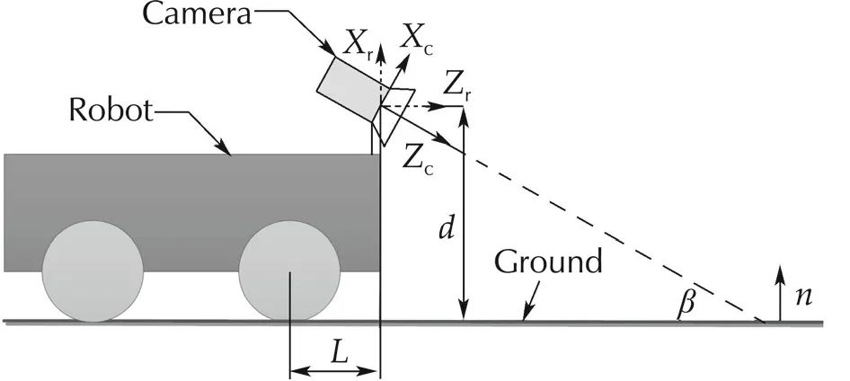
Fig.2 System configuration.
The localcoordinate ofrobotis located atthe principle point of the camera,withzaxis parallel to the ground;the local coordinate of the camera is also located at the principle point andzaxis is parallel to the center line of the camera.The tiltangle ofthe camera isβ,the heightof the principle point with respect to the ground is d,and the distance between the center of driving wheel and principle point is L.In practice,L,d can be measured accurately,but β can only be estimated roughly.
In the global coordinate,the coordinate of robot is expressed as(yr,zr,φ),where(yr,zr)is the position of the principle point and φ is the heading angle of the robot.
3 System modeling
3.1 Non-holonomic kinematic model
As shown in Fig.3,in the coordinate of the robot,the kinematic model is defined as follows:
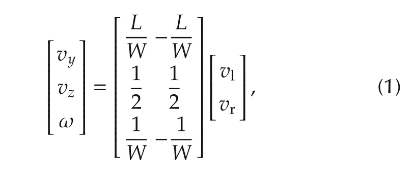
where vy,vzare the lateral and longitudinal velocities,ω is the angular velocity,and vl,vrare the linear velocities of two driving wheels.For simplicity,the control input in the following control system is defined as

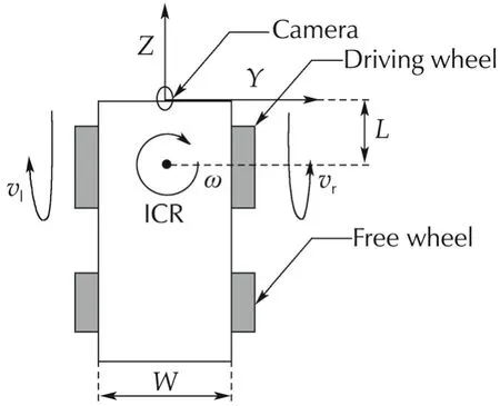
Fig.3 Robot kinematic model.
3.2 Homography-based model
Consider a set of coplanar points,two perspective images of these points can be geometrically related by a homography[18].For our application,suppose that the two images are taken of the ground with the camera mounted on the robot at two different poses related by a rotation Rcand translation tc.The homography is given

where K is the intrinsic matrix ofthe pinhole camera,n is the normalofthe ground in the coordinate ofthe camera at the first pose,and d is the height of the camera.

For simplicity,the camera coordinate is placed at the principle point and skew is neglected after rectification,the intrinsic matrix is given by where ax,ayare the focal lengths in pixel dimensions.Without loss of generality,ax,ayare assumed to be equivalent,which is the case for most cameras.
Besides,in the given configuration,the normal of the ground in the coordinate of the camera is

Consider a planar motion from(0,0,0)to(y,z,φ),the motion of camera can be expressed by
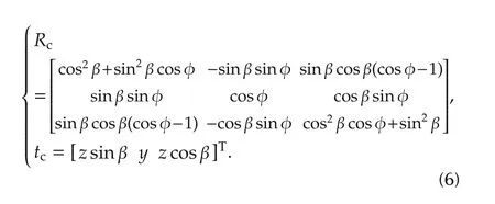
Substitute(4)-(6)into(3),the homography elements are given by(7),where hijis the element of the i th row and the j th column.
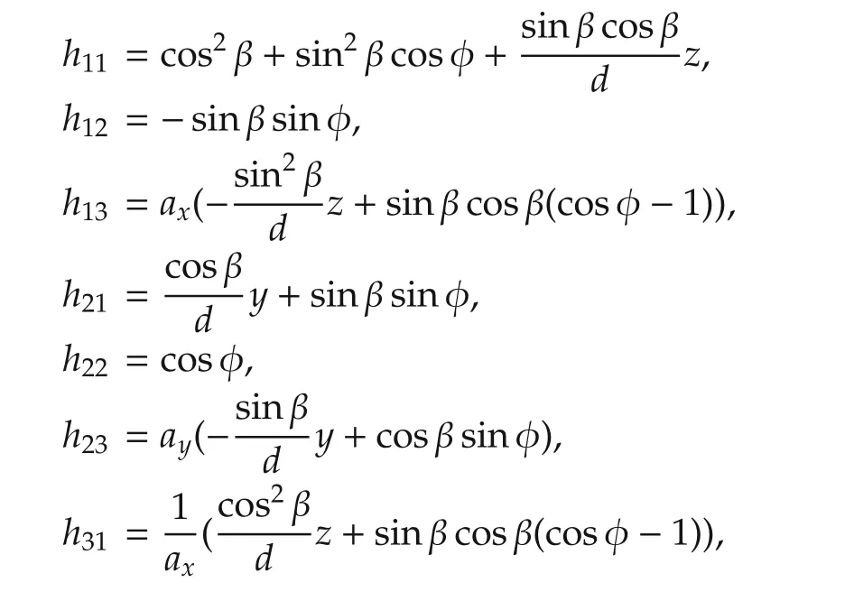

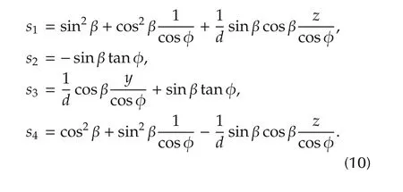
Because the homography matrix has only 8 degrees of freedom,we fix the scale of the homography matrix by normalizing to h22=1.For the other 8 elements,because ax,ayare large,h13,h23,h31,h32are either too large or too small,hence they are more sensitive to noise.We choose h11,h12,h21,h33as the system states,namely s1,s2,s3,s4,which are given by

Remark 1As will be shown in(12),the four elements can determine the pose uniquely,i.e.,the system states are isomorphic with the robot pose.
3.3 Key-frame strategy


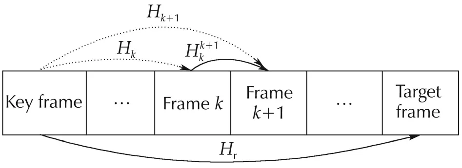
Fig.4 Key-frame strategy.
Since there are always enough corresponding feature point in two neighbouring frames,the target is not necessarily visible in the control process,but only needs to be visible when the robot reaches the key frame.Thus,the field-of-view constraints are loosened.
3.4 Interaction model
Developing expression(7)and(8),we have
Take the derivative of s:
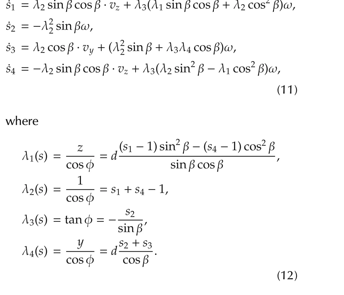
Considering the relation between the global and the ocal coordinate,we have

where˜vy,˜vz,˜ω are velocities in the local coordinate of the robot.Substitute(1)and(13)into(11),the interaction model is given by


is the image Jacobean.
The model(14)is nonholonomic,and its linearized model is not controllable.It has been proved that no continuoustime-invariantfeedback controlexistsforthe regulation problem[19].
4 Control strategy
To deal with the field-of-view constraints of the camera and the nonholonomic constraints of the mobile robot,an iteration strategy is proposed,as shown in Fig.5.At the beginning of each iteration,a subtask is defined,i.e.,the first image frame is chosen as key-frame and the desired state is measured,then a switched controller is used to achieve the subtask.This process is iterated until the finally captured image of iteration k matches the target image best,i.e.,ek< ε,where ekis defined as

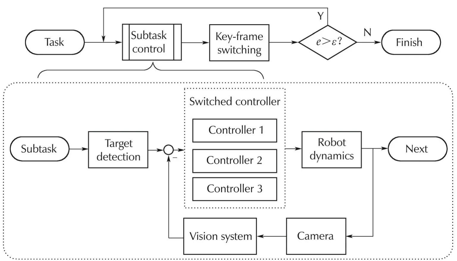
Fig.5 Control strategy.
4.1 Switched controller design
As shown in Fig.6,the motion is divided into three sequential steps,and the point P is the rotation center of the robot at the desired pose.In the first step,the robot rotates until the camera points to P.In the second step,the robot performs a straight line translation to P.In the third step,the robot rotates to the desired pose.From(10)it is clear that s2only relates to the heading angle,s1only relates to z if the angle is constant.Thus,the switched control strategy is defined as follows,where s(k)is the state at the end of Step k,and sris the desired state.
Step 1s2is used as the control variable,the desired value is given by

The controller is

Step 2s1,s2are used as control variables,the desired values are given by

The controller is

Step 3s2is used as the control variable,the desired value is given by

The controller is

Hereinbefore,kw>0,kv<0 are control gains.
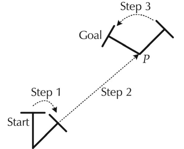
Fig.6 Switched control.
4.2 Stability analysis
Theorem 1The switched controller proposed in Section 4.1 ensures that the system error in every step converges to zero.
ProofThe Lyapunov function is defined in the polar coordinates(r(t),θ(t),φ(t))with the reference origin in the rotation center at the initial pose and θ positive from z-axis anticlockwise.It is given by

where(r*,θ*,φ*)denotes the desired pose of each step.This function is positive definite,its derivative is

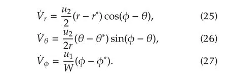
The derivative of Lyapunov function is proven to be strictly negative in each step as follows:


Step 3The robot performs a rotation as in Step 1,and the derivative of Lyapunov function˙V=˙Vφ<0 is guaranteed with the same reasoning of Step 1.□
4.3 Robustness to parameter uncertainty
Parameters used in system are d,L,W,β,here d,L,W are length or height values that can be measured accurately,while β is the tilt angle of the camera that can only be estimated roughly.Theorem 2 guarantees the robustness to the parameter uncertainty with certain limits.


1)The convergence of φ.
In Step 3 which regulates the orientation φ,becauses2is used directly in the feedback control law,the error of φ is not related to the parameters above,and always converges to zero.
2)The convergence ofy,z.
On condition that φ converges,i.e.,in iteration k,φ→0.Developing expression(10)we have
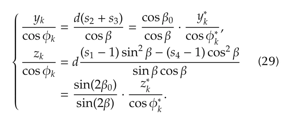


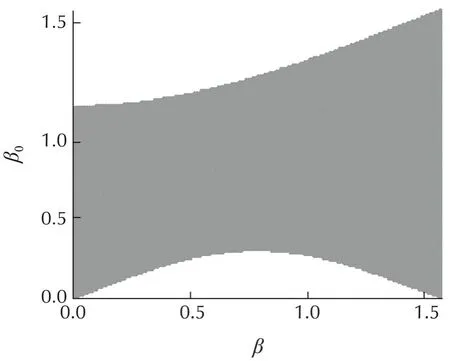
Fig.7 Parameter robustness.
5 Simulation results
In this section,simulation results are presented to show the performance of the proposed method.A virtual framework is used to randomly generate 3D points in a planar scene,and they are projected in the image plane using the pinhole camera model.The homography is computed from the virtual image points.The visual servoing task is depicted as Fig.8,the initial pose is(0,0,0)and the target pose is(500,500,0).The target image is located at(300,700),and the camera-s visible angle is Φ=1.2 rad.The parameters used in simulation are W=40 cm,L=50 cm,d=20 cm,ax=600,ay=600,ε=0.01,kw=1 and kv=-1.
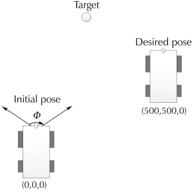
Fig.8 Simulation setup.
To show the effectiveness of the proposed method,simulations are made using the proposed method as well as a switched control strategy based on the T-curve path planning approach[15],which is called T-curve method below in short.Note that the T-curve method does not guarantee robustness to the parameter uncertainty,thus simulations are made with accurate parameters using the proposed method and the T-curve method.Besides,simulation with inaccurate parameters is made using the proposed method to show the robustness.
Simulation results are shown in Figs.9-11.Figs.9 and 10 show the results with accurate parameters,i.e.,β = β0=0.5.Fig.9(c)and Fig.10(b)show that the pose error converge to zero using both methods.From Fig.9(b)we can see that the robot moves straightly towards the goal.Note that in the process there are some poses at which the target may be invisible,that is what it benefits from the key-frame strategy.In contrast,the path of T-curve method is tortuous because of the FOV constraint.Thus,the proposed method gains faster convergence than the T-curve method,and the path length in Cartesian space is apparently shorter than that of T-curve method.
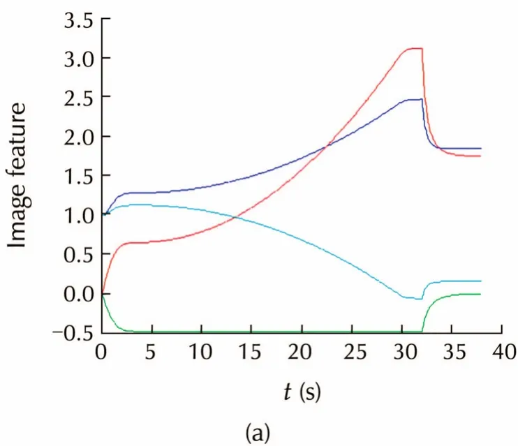
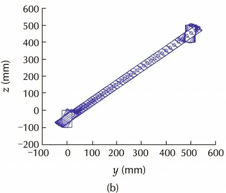
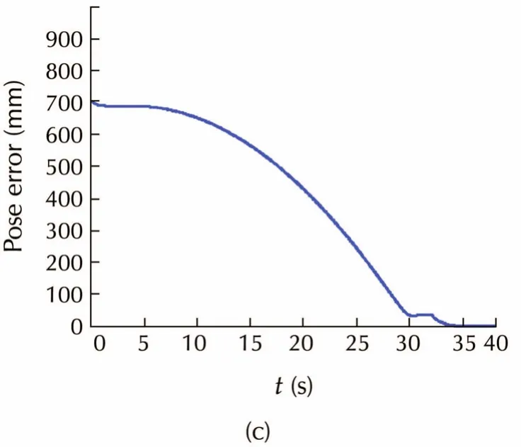
Fig.9 Simulation with accurate parameters using proposed method.(a)Trajectories of system states.(b)Robot trajectory.(c)Pose error convergence.
To validate the robustness,Fig.11 shows the simulation results with inaccurate parameters,i.e.,β=0.5,β0=0.6,which satisfies Theorem 1.After iteration 1,robot pose is regulated to(386,426,0.01)due to the parameter error.After iteration 2,robot pose is regulated to(493,503,0),and finally robot reaches(498,501,0)after iteration 3,which satisfies the stopping rule.Fig.11(d)shows the convergence of the pose error,which is worse than that with accurate parameters,but control error caused by parameter uncertainty can be eliminated,and the performance can be further improved with online parameter identification.
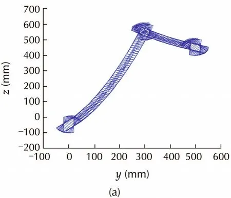
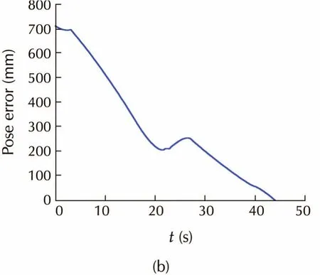
Fig.10 Simulation with accurate parameters using T-curve method.(a)Robot trajectory.(b)Pose error convergence.
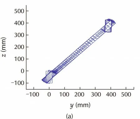
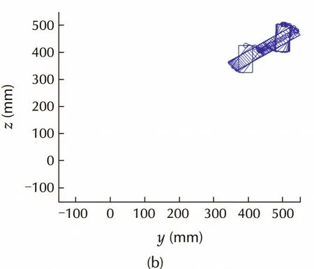
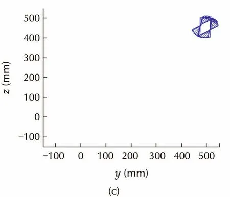
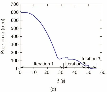
Fig.11 Simulation with inaccurate parameters.(a)Robot trajectory in iteration 1.(b)Robot trajectory in iteration 2.(c)Robot trajectory in iteration 3.(d)Pose error convergence.
6 Conclusions
In this paper,a switched homography-based visual servo control method for nonholonomic mobile robots is presented.Field-of-view and nonholonomic constraints are considered.Compared to conventional methods,a better path can be achieved owing to the key-frame strategy which loosens the field-of-view constraints.A switched controller is designed to deal with the nonholonomic constraints,achieving a shortest path in Cartesian space.Besides,the iteration strategy guarantees control accuracy in the presense of parameter errors.Simulation results show good performance of the method with both accurate and inaccurate parameters.
[1]B.Jia,S.Liu,K.Zhang,et al.Survey on robot visual servo control:vision system and control strategies.Acta Automatica Sinica,2015,41(5):861-873.
[2]T.Fukao,H.Nakagawa,N.Adachi.Adaptive tracking control of a nonholonomic mobile robot.IEEE Transactions on Robotics and Automation,2000,16(5):609-615.
[3]K.Kanjanawanishkul,A.Zell.Path following for an omnidirectional mobile robot based on model predictive control.IEEE International Conference on Robotics and Automation,Kobe:IEEE,2009:3341-3346.
[4]S.Thrun.Simultaneous localization and mapping.Robotics and Cognitive Approaches to Spatial Mapping.Berlin:Springer,2008:13-41.
[5]Y.Fang,W.E.Dixon,D.M.Dawson,et al.Homography-based visual servo regulation of mobile robots.IEEE Transactions on Systems,Man,and Cybernetics-Part B:Cybernetics,2005,35(5):1041-1050.
[6]P.Rives.Visual servoing based on epipolar geometry.IEEE/RSJ International Conference on Intelligent Robots and Systems,Takamatsu:IEEE,2000:602-607.
[7]G.L.Mariottini,G.Oriolo,D.Prattichizzo.Image-based visual servoing for nonholonomic mobile robots using epipolar geometry.IEEE Transactions on Robotics,2007,23(1):87-100.
[8]S.Benhimane,E.Malis.Homography-based 2D visual servoing.IEEE International Conference on Robotics and Automation,Orlando:IEEE,2006:2397-2402.
[9]G.L’opez-Nicol’as,N.Gans,S.Bhattacharya,et al.Homographybased control scheme for mobile robots with nonholonomic and field-of-view constraints.IEEE Transactions on Systems,Man,and Cybernetics-Part B:Cybernetics,2010,40(4):1115-1127.
[10]Y.Mezouar,F.Chaumette.Optimal camera trajectory with image-based control.The International Journal of Robotics Research,2003,22(10/11):781-803.
[11]M.Kazemi,K.Gupta,M.Mehrandezh.Global path planning for robust visual servoing in complex environments.IEEE International Conference on Robotics and Automation,Kobe:IEEE,2009:326-332.
[12]G.Chesi,A.Vicino.Visual servoing for large camera displacements.IEEE Transactions on Robotics,2004,20(4):724-735.
[13]S.Bhattacharya,R.Murrieta-Cid,S.Hutchinson.Optimal paths for landmark-based navigation by differential-drive vehicles with field-of-view constraints.IEEE Transactions on Robotics,2007,23(1):47-59.
[14]P.Salaris,D.Fontanelli,L.Pallottino,et al.Shortest paths for a robot with nonholonomic and field-of-view constraints.IEEE Transactions on Robotics,2010,26(2):269-281.
[15]S.Durola,P.Dan`es,D.Coutinho,et al.Rational systems and matrix inequalities to the multicriteria analysis of visual servos.IEEE InternationalConference on Robotics and Automation,Kobe:IEEE,2009:1504-1509.
[16]G.Allibert,E.Courtial,F.Chaumette.Predictive control for constrained image-based visual servoing.IEEE Transactions on Robotics,2010,26(5):933-939.
[17]S.Bhattacharya,R.Murrieta-Cid,S.Hutchinson.Path planning for a differential drive robot:Minimal length paths-a geometric approach.IEEE/RSJ International Conference on Intelligent Robots and Systems,Sendai:IEEE,2004:2793-2798.
[18]R.Hartley,A.Zisserman.Multiple View Geometry in Computer Vision.New York:Cambridge University Press,2003.
[19]R.Brockett.Asymptotic stability and feedback stabilization.Virginia:Defense Technical Information Center,1983.
his B.E.degree in Control Science and Engineering,Zhejiang University,China,in 2012.He is currently working toward the Ph.D.degree in the College of Control Science and Engineering,Zhejiang University.His research interests include computer vision and vision based control.E-mail:bxjia@zju.edu.cn.
ShanLIUreceived his B.S.degree in Applied Mathematics from University ofScience and Technology of China in 1992,and M.S.and Ph.D.degrees in Control Science and Engineering from Zhejiang University,China in 1995 and 2002,respectively.He is currently an associate professorin the College ofControl Science and Engineering,Zhejiang University.His research interests include adaptive control,iterative learning control,vision-based control,and robot planning and control.Email:sliu@iipc.zju.edu.cn.
†Corresponding author.
E-mail:sliu@iipc.zju.edu.cn.
This work was supported by the National Natural Science Foundation of China(No.61273133).
©2015 South China University of Technology,Academy of Mathematics and Systems Science,CAS,and Springer-Verlag Berlin Heidelberg

杂志排行
Control Theory and Technology的其它文章
- A survey on cross-discipline of control and game
- Nonlinear optimized adaptive trajectory control of helicopter
- Topological structure and optimal control of singular mix-valued logical networks
- Stochastic sub-gradient algorithm for distributed optimization with random sleep scheme
- Linear quadratic regulation for discrete-time systems with state delays and multiplicative noise
