Nonlinear optimized adaptive trajectory control of helicopter
2015-12-06AlirezaABASPOURSeyedHosseinSADATIMohammadSADEGHI
Alireza ABASPOUR,Seyed Hossein SADATI,Mohammad SADEGHI
Aerospace Engineering Department,Malek-Ashtar University of Technology,Babayi Highway,Tehran,Iran
Received 11 May 2014;revised 1 October 2015;accepted 8 October 2015
Nonlinear optimized adaptive trajectory control of helicopter
Alireza ABASPOUR†,Seyed Hossein SADATI,Mohammad SADEGHI
Aerospace Engineering Department,Malek-Ashtar University of Technology,Babayi Highway,Tehran,Iran
Received 11 May 2014;revised 1 October 2015;accepted 8 October 2015
This paperattempts to develop an optimized adaptive trajectory controlsystem forhelicopters based on the dynamic inversion method.This control algorithm is implemented by three time-scale separation architectures.Pseudo control hedging(PCH)is used to protect the adaptive element from actuator saturation nonlinearities and also from the inner-outer-loop interaction.In addition,to augment the attitude control system,two online adaptive architectures that employ a neural network are used.By tuning the neural network based on the system model,a better and faster learning will be achieved,but this is a frustrating and time consuming process.Due to complexity in accurate tuning of neural network,this paper introduces a non-dominated sorting genetic algorithm II(NSGA-II)for off-line optimization of the neural network.Thus,in the proposed method,the neural network can compensate model inversion error caused by the deficiency of full knowledge of helicopter dynamics more accurately.The effectiveness of proposed method is demonstrated by numerical simulations.
Helicopter,nonlinear model,dynamic inversion,PCH,neural network,optimization,NSGA-II
DOI 10.1007/s11768-015-4062-1
1 Introduction
Helicopter dynamics is in general nonlinear,timevarying,and may be highly uncertain.Unmanned helicopters are versatile machines that can perform aggressive maneuvers.The aerodynamic characteristics within acrobatic maneuvers vary widely.This is evident from the wide range of maneuvers executed by expert pilots.
Conventional approaches to helicopter flight control involve linearization of these dynamics about a set of pre-selected equilibrium conditionsortrim pointswithin the flight envelope.These approaches suffer from several disadvantages.First,a linearized model is only an approximation and does not provide complete information of a nonlinear model.Second,the linearized model is obtained based on specific equilibrium or trim point,and as the helicopter moves away from a designed trim point,the control performance can be degraded severely.Therefore,in the linear control schemes gain scheduling is usually necessary for obtaining acceptable performance over an entire flight envelope.Tackling this problem in classical methodologies such as root locusdesign,the designers would require synthesis of many different designs at selected operating points along different maneuvers[1,2].The major advantage of such a design approach is that relatively minor online computations are required and many linear control design techniques such as classical proportional-integral-derivative(PID)control,linear quadratic regulator(LQR)theory,model following,etc.,are available[3].These classical methodologies can be time consuming,thereby increasing both design time and cost during control system development.In hopes of overcoming some of the theoretical limitations and drawbacks of linear controller design,a variety of nonlinear flight control techniques have been investigated.Among these techniques,the feedback linearization method has received much investigation and showsgreatpotential[4-7].The mostsignificant advantage of this synthesis is that gain scheduling becomes inessential.Dynamic inversion(DI)is a candidate methodology of feedback linearization techniques that attempts to eliminate gain scheduling through the inversion and cancellation of the inherent dynamics by replacement with a set of user-selected desired dynamics.However,the primary difficulty in application of the feedback linearization for aircraft control is that detailed knowledge ofthe nonlinearplantdynamics is necessary.
In the present study,a new three loop trajectory controller using the DI method is introduced.First an inner loop that provides high-performance tracking of attitude rate commands is designed,subsequently a middle loop that tracks attitude variables is designed,and finally an outer loop that tracks the position variables is designed.The outer loop generates attitude commands that orient the main rotor forces appropriately to generate required translational accelerations.
This three loop approach generally requires the assumption oftime-scale separation,where the outer-loop bandwidth has to be considerably lower than the middle loop and the inner loop in order to prevent interaction between the loops[8].This three loop structure helps to simplify the control system design.Then,two state feedback-based adaptive controltechnique based on the neural network is applied to the generic helicopter to compensate the model and dynamic inaccuracies.The main advantage of this neural network,simple in its structure,is online adaptive learning that can improve the performance of the controller by compensating the model inversion error,and this ability is obtained by online learning[9].Consequently,the amount of modeling information required can be reduced significantly.The major problem in using artificial neural network(ANN)is parameter tuning,because there is no definite and explicit method to select optimal parameters for the ANN parameters[10].There are several methods which are used to tune the ANN parameters[10-14].In[10]the author used the Taguchi method for obtaining the optimal set of design parameters for a feed forward neural network to achieve high convergence rate during training and the required accuracy during recall.Taguchi’s method of experimental design is widely used in industry for finding important factors in a manufacturing process for achieving useful goals.Reference[11]proved that proper density for training samples in the input space is an important factor in neural network behavior,and they also used Taguchi method for obtaining optimal design parameters of neural network.Improved genetic algorithm was used in[12]to optimize the structure and parameters of neural network.Reference[13]showed that optimizing the neural network with an evolutionary algorithm can improve both learning time and control accuracy of the system.In[14]the authors demonstrated that genetic algorithm has better performance in optimizing the neural network than the Taguchi method.All of aforementioned references in neural network optimization have only optimized a simple neural network for controlling a simple dynamic system.In this paper,the optimization on the neural networks is done for two adaptive neural network in which each of them has three layers.These neural networks are optimized based on the nonlinear complex dynamic of the helicopter and the defined objectives.The advantages of neural network structure in feedback linearization control is already demonstrated in previous research works[15-17].Based on[18],NSGA-II in most problems,is able to find much better spread of solutions and better convergence near the true optimal solution compared to other evolutionary algorithm(EA);therefore,we used NSGA-II method to tune the ANN parameters by considering our objectives in the optimization process.The optimization process of neural network,in addition of achieving our objectives,helps to be faster in training and,consequently,to be faster in model running.This is the first time that a solution is introduced for optimization of neural network for complex system like aeronautical systems.
Besides the adaptation benefits,the control system is still vulnerable to unwanted adaptation,such as moment actuator saturation and associated dynamics as seen by the inner loop.A similar problem occurs with respect to the outer loop due to unwanted adaptation to the inner-loop and collective actuator dynamics.This problem can be tackled by using a new method named Pseudo control hedging(PCH)[15,16],the modification of the inner-and outer-loop reference model dynamics in a way that allows continued adaptation in the presence of actuator saturation.The proposed flight control law is free of a precise helicopter model and capable of easily reusing in similar helicopters with minimum changes.To evaluate the designed controller,a generic modelofYamaha R-50 was used in simulations.The simulation results showed that the proposed design tracks the trajectory with sufficient accuracies.Also,the effectiveness of the neural network compensation in the trajectory tracking problem is investigated when there is a severe gustin helicoptervelocity during the maneuver.The present paper is organized as follows:in Section 2 we proceed with a briefoverview ofmathematicalmodel ofhelicopter,whereas DImethod explained in Section 3,and the neural network,NSGA-II and PCH explained in Sections 4-6 respectively.Then in Section 7 we proceed with the numericalsimulation,while the conclusions are provided in Section 8.
2 Mathematical model of helicopter
Unmanned aerial vehicle(UAV)flight control system needs an accurate and practical dynamic model.Due to the complex nature and physical structure of the helicopter system,obtaining the precise mathematic model is quite difficult.Therefore,usual approximation which derived from system identification and flight data is used[19].
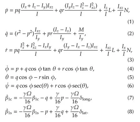
In above equations I=IxIz-I2xzand L,M,N are the rolling,pitching and yawing moment.p,q,r are roll,pitch,yaw rate about the body-fixed frame.φ,θ and ψ are roll,pitch and yaw angle,respectively.β1sand β1care the lateral and longitudinal flapping angles,respectively.The control vector is described by

The main rotor control inputs are the lateral cyclic input(δlat),longitudinal cyclic input(δlong)and collective input(δcol).The pedal collective input of tail rotor(δped)is used to produce yawing moment.For the sake of simplicity,an approximate model of the rotor aerodynamics in hovering condition isused to describe the relationship between the control inputs and the moments[20]:

where L,M,N describe the rolling,pitching and yawing moments,respectively.llat,mlat,nlatare the moments which are related to the δlatcontrol input;llong,mlong,nlongare the moments related to the δlongcontrol input,and lped,mped,npedare the moments which are related to the δpedcontrol input.l0,m0,n0are the initial momentum values.Employing a rotor aerodynamic model in hovering condition has several advantages.First,because of ground tests,the cost and risk can be reduced.Second,moments can be accurately measured on the ground by various equipments.Third,the quantity of the test data can be greatly reduced.The relation between the collective input and thrust equations are extracted from[21].
3 Dynamic inversion
In this section,we present a feedback linearization technique known as dynamic inversion(DI).DI is a control design technique which uses a feedback signal to cancel inherent dynamics and simultaneously obtains a desired dynamic response[6].To exemplify the working principle of the nonlinear DI(NDI),consider a system of order n with the same number m of inputs(u)and outputs(y)and affine in the control inputs.Moreover,the outputs coincide typically to the control variables and are assumed to be physically similar(as an example,attitude angles).This type of system can be mathemati-cally represented by

where f and h are vector fields in Rnand Rm,respectively,and G is an n×m controleffectiveness matrix.This system can be given any desired dynamics by suitable choice of the control input(u)[22].For example,the stable first order dynamics given by(12)can be chosen.

Here ωcis a design parameter which is chosen by designer to obtain the desired performance,and the subscript c denotes the commands.The required control can then be computed by inverting(11)to give

Substitution of(13)into(11)clearly yields the desired dynamics of(12).The method can be extended to higher order systems provided g(x)is invertible.In flight vehicle control problems,g(x)may be invertible if there are sufficient control effectors;however,there will often be conditions where g(x)is nearly singular.This would result in excessively large commands and saturation of control effectors.The near singularity of g(x)is due to the fact that the control moment effectors produce very small forces and thus provide very little direct control of attitude angles.Thus,it is difficult to use the DI directly for flight vehicle with more or less standard control effectors.The stability of dynamic inversion method is mathematically proved in[23].In the mentioned reference the DI controller stability was examined through the Lyapanov theory,and it is demonstrated that g(x)is exponentially stable for large enough inner-loop gain ω*.Singular perturbation theory is another alternative that can be applied to(13)for analyzing the stability of the system[24].By using standard singular perturbation theory results,it is relatively simple to show that the origin of the system defined by(13)is exponentially stable for large enough inner-loop gain ω*.In this paper,the problem associated with the invertibility of g(x)was overcome by separating the dynamics into slow,fast,and fastest subsystems in three loops by using timescale separation assumption,and subsequently choosing large ω*gains.The fastest subsystem corresponds to the body axis angular rates by an exact inner loop inversion using the three control effectors,lateral cyclic,longitudinal cyclic and pedal collective.The semi-fast subsystem corresponds to the attitude angles and the slow subsystem corresponds to the positions variables.
3.1 Time scale separation
Different time scales in a dynamical system can be used as an advantage to simplify its complexity by separating the dynamics based on their rate of changes.This kind of time scale separation exists naturally in various fields of engineering,applied mathematics,and even biological sciences and it is based on the presence of some parasitic parameters.Time scales in dynamical systems can be proved by singular perturbations theory[25].Several options for selecting time scales are presented in[25],and provided with examples in different aerospace systems.By applying time scale separation principle,slow dynamics parameters are considered constants in the inner loop(fast dynamics),because they evolve more slowly.Moreover,the DI of the outer loop(slow dynamics)is executed assuming that the states of the fast dynamics obtain their commanded values rapidly,and this is only valid if there is enough time scale separation between the loops.Otherwise,a weak separation between the different time scales can degrade the overall performance of the controller.However,itisdemonstrated using Lyapunov theory thatifthe inner loop gains are sufficiently large,then the system is exponentially stable about the constant commanded values of the outer loop states[23].This property was practically applied for a missile control system in[23].A simple procedure to prove existence of a difference in the time scale among attitude angles,angular rates,and position rates is to introduce a unit step to each control inputs and measure the time derivative of responses in the transient instant.In this simulation,a step input is given to the helicopter δlong,δlatand δpedcontrol inputs separately,and the results are shown in Table 1.

Table 1 Verification of the time scale separation between attitude angles and rates.
Based on the obtained result in Table 1,it can be clearly noticed that the time-scale separation can be considered due to speed difference between the control loops.
3.2 Rate controller
The attitude rates are the fastest states in helicopter dynamic model.As the name indicates,the control variables of this inner loop are the angular rates of the helicopter.When designing a flight control system with three-time-scale assumption,the inner-loop controller is designed to control the fastest states by using the control input(δlong,δlat,δped),where the desired values of the fast states are given by the middle loop.Now for using the DI based on(11),the fast differential equation can be separated as

while g(x)and[fpfqfr]can be derived from(1)-(3)and(10)as follows:
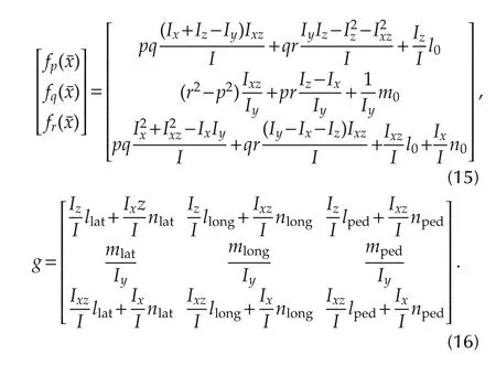
By considering(13),the controller of inner loop yields

While the desire angular rates defined with following equation:

where ωp,ωqand ωrare the inner loop control gains which are chosen by designer to obtain the desired performance,and the subscript c denotes the commands.
3.3 Attitude controller
In the middle loop,the controller is designed to control the semi fast states,and the output of the middle loop used as inner-loop commands.As the name indicates the semi fast states are the attitude angles which described in(4)-(6).It assumes that the fast states track their commanded values instantaneously and that the control surface deflection has no effect on the middleloop dynamics.
As it can be seen on(4)-(6),the angular rate commands can be easily extracted as follows:

While the desired attitudes defined as the following equation:

where ωφ,ωθand ωψare outer loop control gains which are chosen by designer to obtain desired performance and φc,θc,ψcare the input commands from the outer loop.
3.4 Position controller
Once again,another time scale separation is assumed between the translational and rotational dynamics.With regard to this assumption,a new control loop for the position control can be defined.This control loop aims to track the trajectory commands(inertial positions:X(North),Y(East),Z(up)),and the output variables of the controllerare the helicopterrolland pitch attitude angles(φc,θc)and the collective control input of the main rotor(δc)for the vertical speed.For horizontal control,an approach based on an approximate dynamic inversion is adopted[26].In this approach,the second derivatives of X,Y,Z defined as the pseudo control variables as follows:

By transforming the designed inertialcommandsto body fixed frame,we have

where TIBis transformation matrix from the body fixedframe to the inertial coordinate.Since the force generated by the cyclic and pedal input are relatively small compared to those generated by the collective,only the collective control terms are retained in the force equations.Also the X-direction force(Fx)and Y-direction force(Fy)are small compared to the magnitude of the Z-direction force((Fz);and therefore,they are neglected in order to obtain analytical solutions for θcand φc.
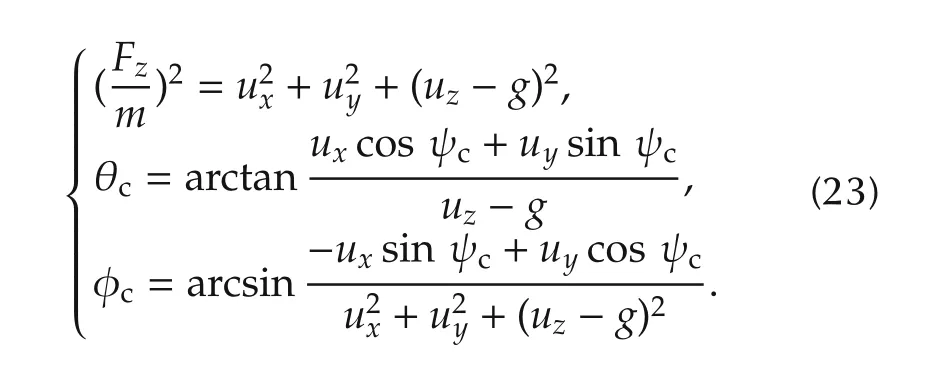
To obtain the collective controlterm(δcol),the linearized Z-direction force equation of motion should be solved,here the Z force that previously denoted as Fz,simply denoted as Z.The stability derivatives Z*are simply the derivatives of Z with respect to a certain variable here denoted by*.If the cross-coupling effects are neglected for the following development,the main contributions for the forces on the body Z-axis come from the states and control inputs associated with the longitudinal motion of the vehicle.If the remaining contributions are neglected and denoted x-xtrimas Δx,the Z force can be approximated around a given trim condition as

If the trim condition is chosen to be hovering flight,the Z force only has to balance the effects of gravity on the helicopter and thus

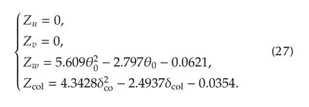
By extracting the collective term with considering zero condition trim,in hovering flight we have

The stability derivatives(Z*)in(26)are obtained from[21]
Proportional derivative(PD)controller is used to shape the position of each axis response as follows:

The proportional(kp)and derivative(kd)control gains are as follows:

where ζ is the damping ratio,and ωnis the un-damped natural frequency.The PD gains are calculated to satisfy the system specifications given as 1%settling time(ts=2 s)and Max.Overshoot(Mp=8%)for good performance.The corresponding damping ratio is 0.869 and the natural frequency is 2.646.
The overall view of three loop control design used in this paper is depicted on Fig.1.

Fig.1 Overall view of adaptive dynamic inversion control designed for helicopter.
4 Adaptive neural network design
In this section,a three layeronline learning neuralnetwork is described for use as an adaptive element(uad).Generally,it is noticed that the neural network is capable of approximating highly nonlinear systems within desired accuracy[27].In this paper,a neural network is used in order to approximate the model error.
An adaptive NN signal can be expressed as(30)[27]:

where V and W are the weight matrices that joint the first layer to the second layer,and the second layer to the third layer,respectively.σ is a sigmoid activation function,and μ is the neural network input that can be defined as μ=[1 xT]T.

where ΓWand ΓVare the learning coefficient matrix,E is model dynamic error,and P is diagonal positive definite matrix which can be extracted from(34).

The scalarfunctionσis a sigmoid activation function that represents the “firing”characteristics of the neuron:
The factor a is the activation potential,and should normally be a distinct value for each neuron.The structure ofthree layers neuralnetwork which is used in this study can be seen on Fig.2.
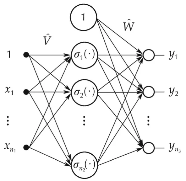
Fig.2 Structure of three-layer neural network.

5 Optimizing neural network by using NSGA-II
Genetic algorithm(GA)is a directed random search technique that is widely applied in optimization problems.This technique is especially useful for complex optimization problems where the numberofparameters is large and the analytical solutions are difficult to obtain.As we mentioned above,tuning the ANN is a time consuming and frustrating process.Therefore,in this paper we suggest a non-dominated sorting-based multiobjective EA(MOEA),called non-dominated sorting genetic algorithm II(NSGA-II).This method is selected to tackle these problems of other MOEA methods:1)computational complexity,2)non-elitism approach,and 3)the need for specifying a sharing parameter[18].By using this method the learning coefficients(ΓWand ΓV)are optimized.Tuning these coefficients which have significant role in behavior of the adaptive neural network is essential to have an ideal adaptive element.In this off-line process,the learning coefficients are tuned by NSGA-II evolutionary algorithm.The optimization process considered following objectives:
1)Minimizing the position tracking error.2)Minimizing the attitude tracking error.
The position tracking error is the most important factor in our designing.An accurate position tracking needs accurate attitude tracking,and so our second objective is to reduce attitude tracking error.

In our optimization process,the population size is 20,and the optimization repeated for 100 generation.The range of decision variable for ΓWis selected between-0.7 and 0,and the range of decision variable for ΓVis selected between-400 and 0.These variables range selection is based on numerous simulation results to eliminate the singularity in simulations.
6 Pseudo control hedging
The NDI control design was derived without any actuator dynamic consideration.The actuator saturation is a usual phenomenon which happens during aggressive maneuvers,especially in helicopter which has limited actuator deflections.If these effects are not taken into account,the performance of the overall controller may be severely degraded,and the stability of the system may even put it at risk.For solving this issue,an adaptation technique known as PCH is introduced[28].The PCH automatically moves the reference models in the opposite direction(hedge)by an estimate ofthe amount.This prevents the continued effort to track the original commanded references when the saturation effects are experienced.
In order to implement the hedging of the commanded signal,a first-order reference model(RM)is adopted.
This reference model has to keep the desired reference from being physically unachievable via a filter.It is especially useful to compute the derivatives of command variables,which can be used by the controller as feed-forward terms.The structure of reference model is shown on Fig.3.Here,kis a diagonal gain matrix and the saturation element imposes the desired limitation into the commanded references.The signal sent to the control system corresponds to the state vector of the RM using information about the system.
It is possible to estimate the value of a virtual control(v)thatcorresponds to the physicalcontrol(u).Recalling(12),the pseudo-control hedge can be defined as

wherevhis the PCHsignalwhich guarantees the tracking of reference model,ucomis the controller command for tracking of the desired references,anduis the achievable control command.Now with considering the RM showed in Fig.3 and(12),the PCH can be used in NDI controller as Fig.4.

Fig.3 Structure of reference mode.
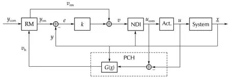
Fig.4 Structure of PCH in a NDI control loop.
Moreover,if the control system presents a multi-loop design and the time scale separation principle is applied,it is assumed that the outer-loop bandwidth is much lower than that of the inner loop.With regard to this assumption,the PCH can be used in several loop design.In this paper,two PCH structure are used in the attitude and rate controller loop in order to adjust the behavior of the outer loop when the bandwidth of the inner loop is not separated enough.Note that the outer loop sees the commanded references of the inner loop as control inputs which are just like real actuators,and characterized by the practical limitations and speed of response.
7 Numerical simulations
In this paper,we designed an optimized adaptive nonlinear controller for a generic model of small scale helicopter.The helicopter model that we selected for this research is a Yamaha R-50,which is used for evaluation of many researches[17,29,30].
The control system designed in this paper will be next used as an autopilot capable of achieving precise maneuvering.As demonstrated above,this control system allows to decouple the responses of the helicopter associated with different axes,and pilot can directly enforce the desired characteristics to each one.A desired trajectory via a command filter which is shown on Table 2(Case I)commanded to the system,meanwhile,by using NSGA-II the adaptive neural network is optimized.As it can be seen on Fig.1,two neural networks are used in this paper,and so 12 parameters should be tuned(6 parameter for each NN).Due to the defined objectives,the NSGA-II optimization algorithm gives multiple choices.The result of optimization process is shown on Fig.5.

Table 2 Command specification.
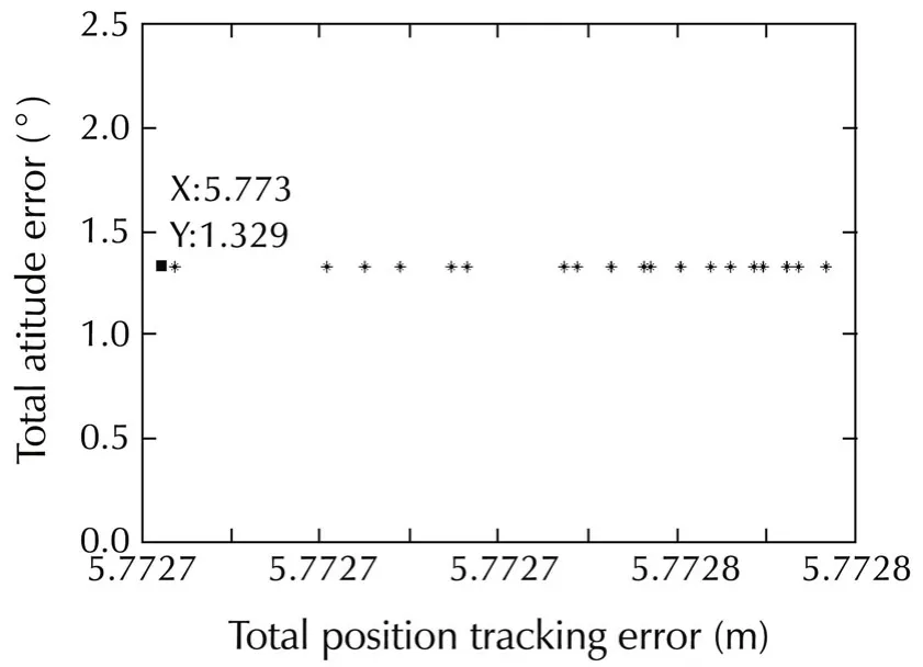
Fig.5 The result of optimization using NSGA-II after 100 generation.
As it can be seen on Fig.5,multiple choices are obtained.Obviously,the dotted point has the best condition for our objective.By selecting this point,the adaptive neural network learning coefficient quantized as follows:
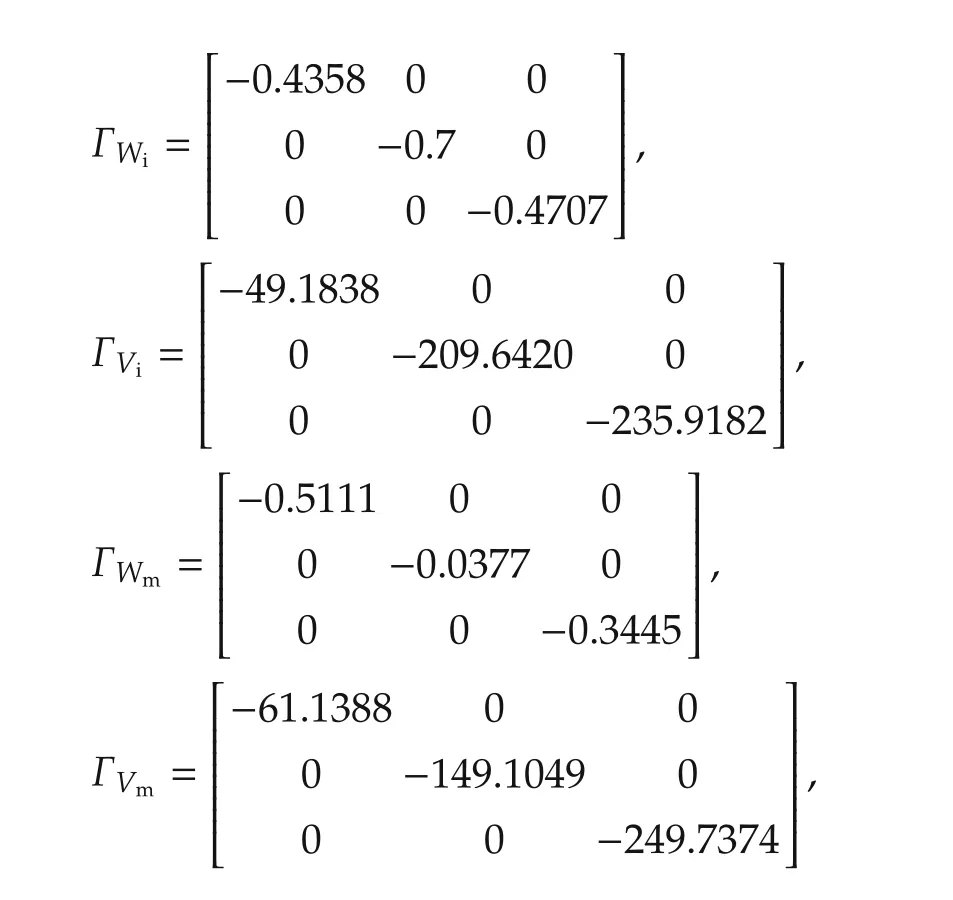
where ΓWi,ΓViare the learning coefficient of inner-loop adaptive neural network,and ΓWm,ΓVmare the learning coefficient of middle-loop adaptive neural network.
In the simulations,severalscenarios are considered to examine the introduced controlsystem.The aim ofthese simulations is to evaluate the effect of neural network tuning in control performance of the system.The numerical simulations of defined scenarios are performed via MATLAB/SIMULINK software.Two maneuvers are presented in which their specifications are provided on Table 2.In the first scenario,Case I command is applied to the system.Then in the second scenario,a gust is applied to the system(with Case I command).Finally,the control system is tested over a circular maneuver(Case II without gust).This circular maneuver is given to examine the control ability of the system over sever maneuvers,and to check the capability of the precision control of simultaneous pitch,roll,yaw,and heave motions.
As it can be seen on Fig.6 the control system tracks the command trajectory with proper accuracy(less than 0.5 m).In Fig.7 it can be seen that attitude commands are tracked precisely.Fig.8 shows that the command deflection changed in a smooth way with minimum amplitude,therefore,the actuatorwould neverface any saturation.This smooth changing of actuators is the result of using PCH method that avoids actuator saturation.
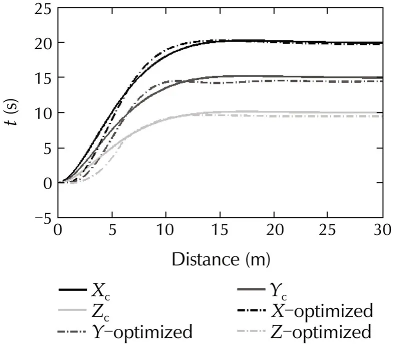
Fig.6 Trajectory track in Case I.
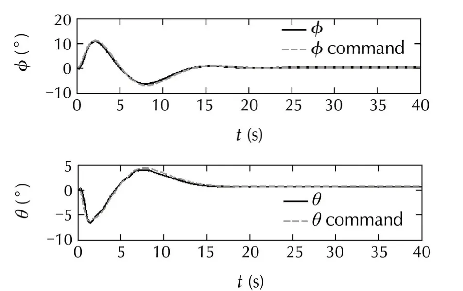

Fig.7 Attitude command tracking in Case I(without gust).
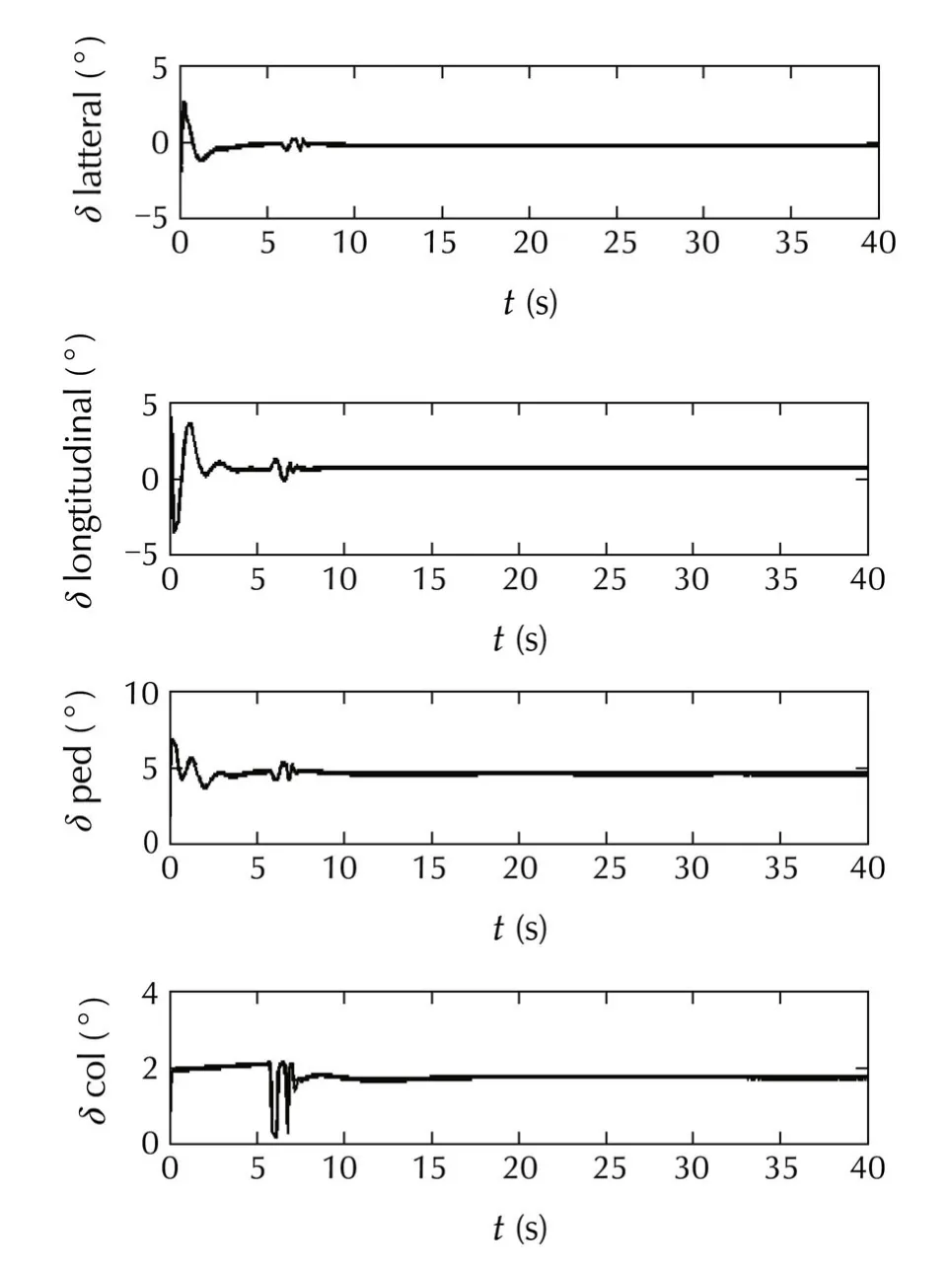
Fig.8 Control deflection in Case I(without g ust).
In the previous researches,the advantages of using neural network in dynamic inversion controller were demonstrated[17,31].Therefore,in these numerical simulations the control performance of the optimized and ordinary neural network(without optimization)is compared.In the second scenario,for robustness analyzes of the system,the control system is tested over a gustwhich isdepicted on Fig.9.Thiswind gustis applied via MATLAB Dryden toolbox to the system through north and down.In this scenario,the control performance of tuned neural network and the neural network without tuning is compared in presence of wind gust.The results are depicted on Figs.10-15.The ordinary neuralnetwork(nottuned)coefficients are obtained from[9],and its coefficients are available on Appendix A2.In the following figures the controller with optimized NN adaptive elementis named “optimized NN”,and the controllerwithout adaptive element is named “ordinary NN”.Fig.10 shows that the tracking error of φ is clearly decreased in the introduced method.Also,a clear reduction in control error of the θ can be seen on Fig.11.Fig.12 shows that the introduced method reduced the control error of ψ either.
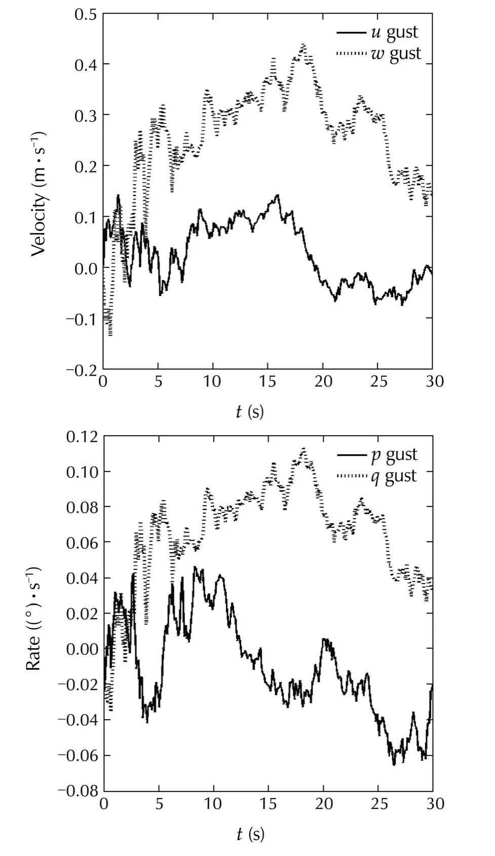
Fig.9 Gust which is inserted to the system.
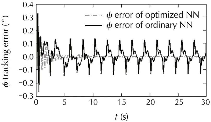
Fig.10 Comparison in tracking φ angle between introduced method and ordinary adaptive neural network controller(in gust situation).
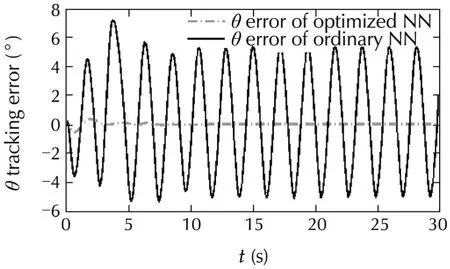
Fig.11 Comparison in tracking θ angle between introduced method and ordinary adaptive neural network controller(in gust situation).
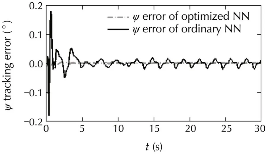
Fig.12 Comparison in tracking φ angle between introduced method and ordinary adaptive neural network controller(in gust situation).
Figs.13-15 show that the introduced method has a significant effect on reduction of the trajectory missdistance.This reduction in miss-distance can be really helpful for helicopters that perform their mission in civil areas,where a small mistake in their trajectory control can be disastrous.
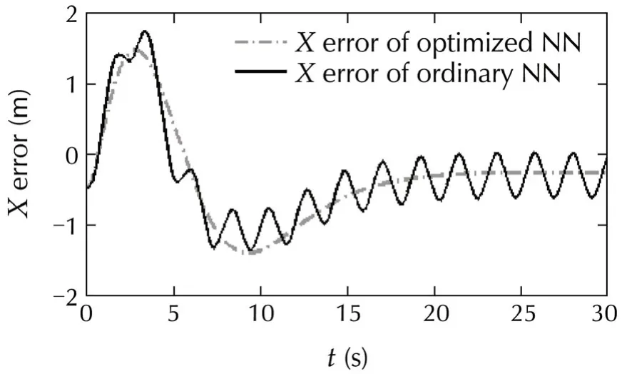
Fig.13 Comparison in tracking X direction trajectory command between introduced method and ordinary adaptive neural network controller(in gust situation).
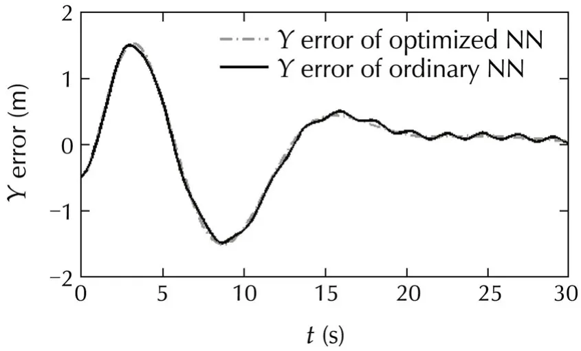
Fig.14 Comparison in tracking Y direction trajectory command between introduced method and ordinary adaptive neural network controller(in gust situation).
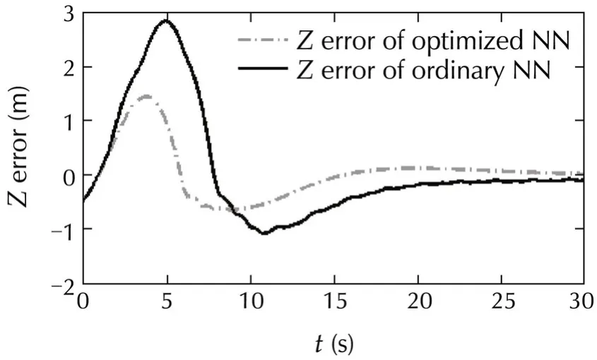
Fig.15 Comparison in tracking Z direction trajectory command between introduced method and ordinary adaptive neural network controller(in gust situation).
Finally,the designed control system is tested over a circular maneuver(Case II).The results are shown on Figs.16-19,and these figures show that tuning the neural network based on nonlinear model of aircraft can improve the neural network ability to decrease the attitude control error.Moreover,these figures demonstrate that this tuning can reduce the trajectory error,because an accurate trajectory control needs accurate attitude control.
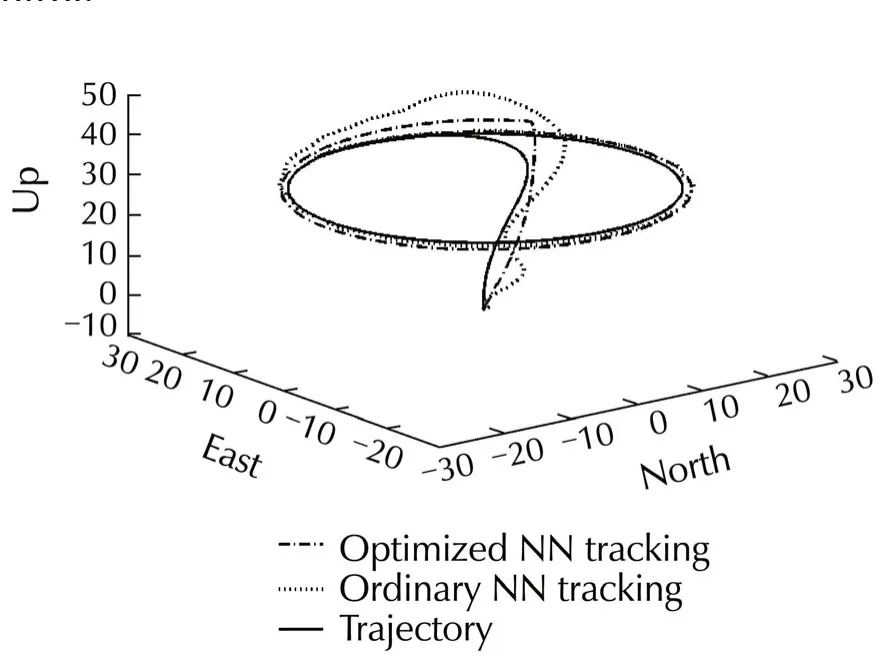
Fig.16 Trajectory tracking in Case II.
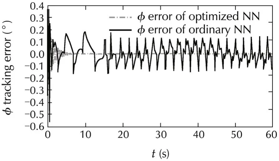
Fig.17 φ tracking in Case II.
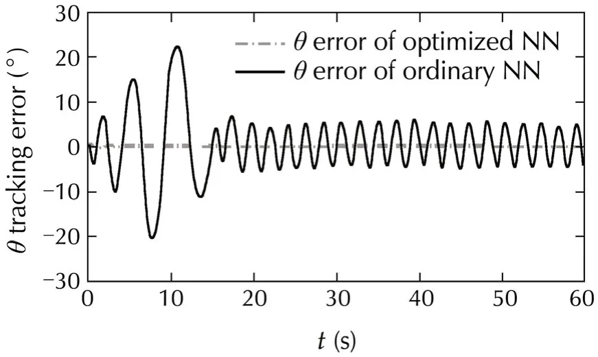
Fig.18 θ tracking in Case II.
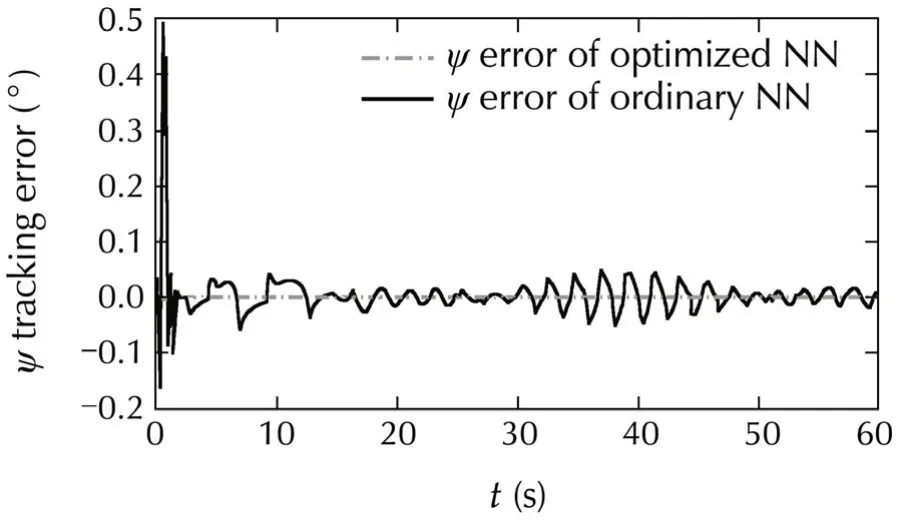
Fig.19 ψ tracking in Case II.
8 Conclusions
In this paper an autonomous nonlinear optimized adaptive trajectory control system is designed for an approximate nonlinear model of Yamaha R50 helicopter model.The control system was designed based on the DIcontrolprocedure using time scale separation in three loops.This three loops design helps to simplify the control design.PCH method was used for actuator saturation avoidance and two adaptive neural networks used for elimination of the model error.For a better adaptation,the neural networks were tuned by NSGA-II.By tuning the neural networks in off-line mode,a faster learning was achieved and the trajectory error reduced.Furthermore,the simulation time reduced as well.The results confirm that the designed controller tracked the desired trajectory with proper accuracy.The robustness of system tested over a wind gust,and the simulations demonstrated that the control system is robust against severe winds.The effect of NN adaptive controller was clear in reduction of the attitude error,and also it reduced the position error.
From these results,it can be concluded that the introduced control system design with minimum of model data is successful in desired trajectory tracking,and the introduced method which is suggested to tune the neural network is very effective for achieving a better and faster adaptation.
[1]R.C.Dorf,R.H.Bishop.Modern Control Systems.9th ed.Upper Saddle River:Prentice-Hall,2001.
[2]B.Stevens,F.Lewis.Aircraft Control and Simulation.New York:Wiley,1992.
[3]B.S.Kim,A.J.Calise.Nonlinear flight control using neural networks.Journal of Guidance Control and Dynamics,1997,20(1):26-33.
[4]D.J.Bugajski,D.F.Enns.Nonlinear control law with application to high angle-of attack flight.Journal of Guidance Control and Dynamics,1992,15(3):761-767.
[5]G.Meyer,L.Cicolani.Application of nonlinear systems inverses to automatic flight control design-system concepts and flight evaluations.Theory and Applications of Optimal Control in Aerospace Systems.Neuilly sur Seine,France:AGARD,1981:AGARD-AG-251.
[6]J.Reiner,G.J.Balas,W.L.Garrard.Robust dynamic inversion for control of highly maneuverable aircraft.Journal of Guidance Control and Dynamics.1995,18(1):18-24.
[7]A.Abaspour,M.Sadeghi,H.Sadati.Using fuzzy logic in dynamic inversion flight controller with considering uncertainties.The 13thIranianConferenceonFuzzySystems(IFSC),New York:IEEE,2013:DOI 10.1109/IFSC.2013.6675662.
[8]J.Reiner,G.J.Balas,W.L.Garrard.Flight control design using robust dynamic inversion and time-scale separation.Automatica,1996,32(11):1493-1504.
[9]S.H.Sadati,M.Sabzeh Parvar,M.B.Menhaj,et al.Backstepping controller design using neural networks for a fighter aircraft.European Journal of Control,2007,13(5):516-526.
[10]J.F.C.Khaw,B.S.Lim,L.E.N.Lim.Optimal design of neural networks using the Taguchi method.Neurocomputing,1995,7(3):225-245.
[11]G.E.Peterson,D.C.St Clair,S.R.Aylward,et al.Using Taguchi’s method of experimental design to control errors in layered perceptrons.IEEE Transactions on Neural Networks,1995,6(4):949-961.
[12]F.H.F.Leung,H.K.Lam,S.H.Ling,et al.Tuning of the structure and parameters of a neural network using an improved genetic algorithm.IEEE Transactions on Neural Networks,2003,14(1):79-88.
[13]M.H¨usken,Y.Jin,B.Sendhoff.Structure optimization of neural networks for evolutionary design optimization.Journal of Soft Computing January,2005,9(1):21-28.
[14]M.Bashiri,A.F.Geranmayeh.Tuning the parameters of an artificial neural network using central composite design and genetic algorithm.Scientia Iranica,2011,18(6):1600-1608.
[15]E.N.Johnson,A.J.Calise,J.E.Corban.Reusable launch vehicle adaptive guidance and control using neural networks.AIAA Guidance,NavigationandControlConference,Montreal,Canada:AIAA,2001:DOI 10.2514/6.2001-4381.
[16]E.N.Johnson.Limited Authority Adaptive Flight Control.Ph.D.thesis.Atlanta:School of Aerospace Engineering,Georgia Institute of Technology,2000.
[17]E.Johnson,S.Kannan.Adaptive trajectory control for autonomous helicopters.AIAA Journal of Guidance,Control,and Dynamics,2005,28(3):524-538.
[18]K.Deb,A.Pratap,S.Agarwal,et al.A fast and elitist multiobjective genetic algorithm:NSGA-II.IEEE Transactions on Evolutionary Computation,2002,6(2):182-197.
[19]B.Mettler.IdentificationModelingandCharacteristicsof Miniature Rotorcraft.New York:Springer,2003.
[20]S.Zeng,J.Zhu.Adaptive compensated dynamic inversion control for a helicopter with approximate mathematical mode.International Conference on Computational Intelligence for Modeling Control and Automation,Sydney:IEEE Computer Society,2006:DOI 10.1109/CIMCA.2006.34.
[21]B.Ren,S.S.Ge,C.Chen,et al.Modeling,Control and Coordination of Helicopter Systems.New York:Springer,2012.
[22]D.Enns,D.Bugajski,D.Hendrick,et al.Dynamic inversion:an evolving methodology for flight control design.International Journal of Control,1994,59(1):71-91.
[23]C.J.Schumacher,P.P.Khargonekar,N.H.McClamroch.Stability analysis of dynamic inversion controllers using timescale separation.Proceedings of the AIAA Guidance,Navigation,and Control Conference and Exhibit,Boston:AIAA,1998:AIAA paper 1998-4322.
[24]H.K.Khalil.Nonlinear Systems.New York:Macmillan Publishing Company,1992.
[25]D.S.Naidu,A.J.Calise.Singular perturbations and time scales in guidance and control of aerospace systems:a survey.Journal of Guidance,Control and Dynamics,2001,24(6):1057-1078.
[26]J.V.R.Prasad,A.M.Lipp.Synthesisofa helicopternonlinearflight controller using approximate model inversion.Mathematical and Computer Modeling,1993,18(3/4):89-100.
[27]Nakwan Kim.Improved Methods in Neural Network Based Adaptive Output Feedback Control,With Application To Flight Control.Atlanta:School of Aerospace Engineering,Georgia Institute of Technology,2003.
[28]E.N.Johnson,A.J.Calise.Pseudo-controlhedging:a new method for adaptive control.Proceedings of the Advances in Navigation and Control Technology Workshop,Alabama,2000.
[29]D.H.Shim,H.J.Kim,S.Sastry.A flight control system for aerial robots:algorithms and experiments.IFAC Control Engineering Practice,2003,11(2):1389-1400.
[30]M.Sugeno,W.Howard,H.Isao,et al.Intelligent control of an unmanned helicopter based on fuzzy logic.Proceedings of the 51st American Helicopter Society(AHS)Annual Forum,Antalya,Turkey,1995:791-803.
[31]S.Lee,C.Ha,B.S.Kim.Adaptive nonlinear control system design for helicopter robust command augmentation.Aerospace Science and Technology,2005,8(3):241-251.
[32]C.Munzinger.Development of a Real-time Flight Simulator For an Experimental Model Helicopter.Master thesis.Atlanta:School of Aerospace Engineering,Georgia Institute of Technology,1998.
[33]G.D.Padfield.HelicopterFlightDynamics:TheTheory and Application of Flying Qualities and Simulation Modeling.Washington D.C.:AIAA Educational Series,1995.
Appendix
A Helicopter specif i cation
In this section,the helicopter specifications and assumptions which were used in this paper are presented.
A1 Yamaha R-50 data
This appendix contains data for the R50 helicopter,which are available on Table a1[32].
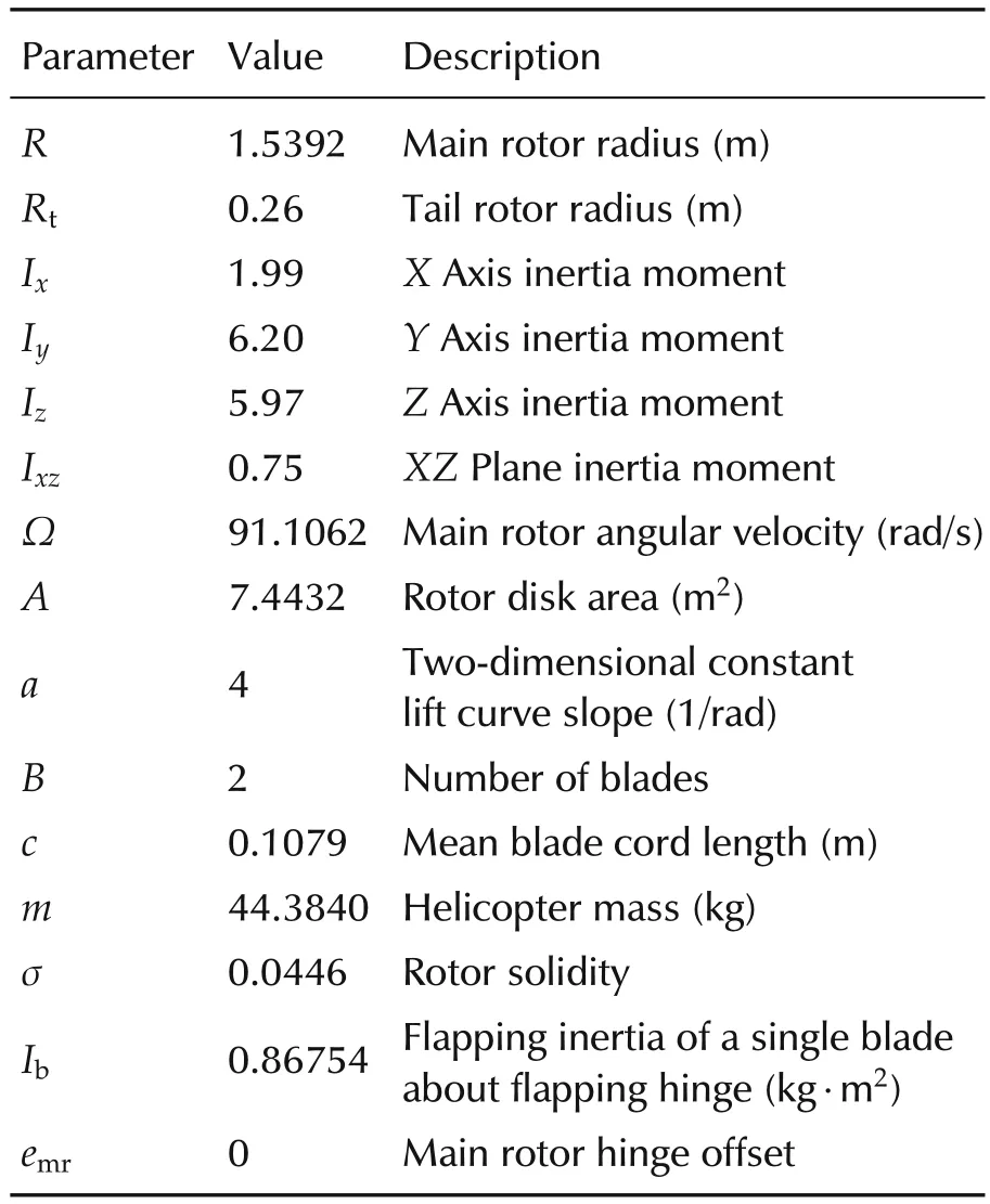
Table a1 Yamaha R-50 data.
A2 The ordinary neural network(not tuned)
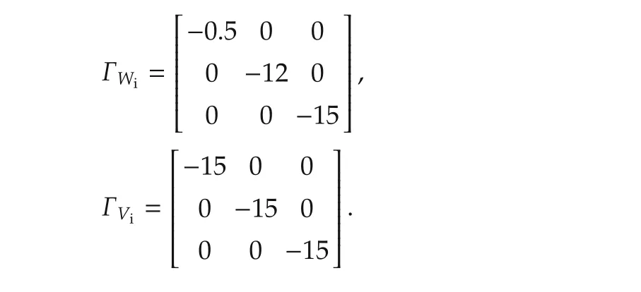
A3 Assumptions
For the development of the nonlinear 6-DOF helicopter model adopted throughout this paper,the following assumptions are made.
1)Teetering rotor:All rotors are modeled as teetering rotors,which means that the blades flap hinge-less in the center rotor hub and that it does not curve.This assumption can be made because the amplitude of the flapping motion,in response to gusts and control inputs,is similar for the different types of rotors[33].
2)Blade twist:Blade twist means that the blade is twisted along the length of the blade to compensate for uneven lift.All the blades on the helicopter are assumed without blade twist.
3)Air density:As the altitude of the operating envelope is limited,the density of the air is considered constant.
4)Drag on fuselage:Because the helicopter is in hover and the wind velocity is defined to be zero,any drag on the fuselage will ignorable.
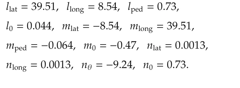
5)Rotor aerodynamics:The parameters which are used in the linearapproximate modelofthe rotoraerodynamics(equation(10))are[17]
Alireza ABASPOURwas born in Mashhad,Iran,in 1988 and received his B.Sc.degree in Control Engineering from Sadjad University,Iran,in 2010,and M.Sc.degree in Guidance and Control Engineering from Maleke Ashtar University Of Technology(MUT),Iran in 2013.His current research interests are nonlinear control,rotorcraft dynamic and control,and artificial intelligence.Currently,he is pursuing his Ph.D.degree of Control Engineering at Wichita State University,Wichita,Kansas,USA.Email:alireza.abaspour@gmail.com.
Seyed Hossein SADATIis an assistant professor in the Department of Aerospace Engineering at Maleke Ashtar University of Technology(MUT),Tehran,Iran.He received his Ph.D.in Aerospace Engineering from Amirkabir University in 2008.He has published more than 40 journal and conference papers in the area of Aerospace Engineering.His current research interests include the control system design for aircraft,trajectory optimization,nonlinear control,optimal control,neural network and fuzzy Control.Email:hsadati@aut.ac.ir.
Mohammad SADEGHIwas born in Saveh,Iran,in 1987,and received his B.Sc.degree in Electronic Engineering from Chamran University,Iran,in 2010,and M.Sc.degree in Guidance and Control Engineering from Maleke Ashtar University Of Technology(MUT),Iran in 2013.His current research interests are nonlinear control,aircraft flight formation control and intelligence control systems.Currently,he is a researcher in space research institute in Tehran,Iran.Email:msadeghi198465@yahoo.com.
†Corresponding author.
E-mail:alireza.abaspour@gmail.com.Tel.:+1(316)5166525.
©2015 South China University of Technology,Academy of Mathematics and Systems Science,CAS,and Springer-Verlag Berlin Heidelberg

杂志排行
Control Theory and Technology的其它文章
- A survey on cross-discipline of control and game
- Switched visual servo control of nonholonomic mobile robots with field-of-view constraints based on homography
- Topological structure and optimal control of singular mix-valued logical networks
- Stochastic sub-gradient algorithm for distributed optimization with random sleep scheme
- Linear quadratic regulation for discrete-time systems with state delays and multiplicative noise
