Dy(III)离子在LiCl-KCl熔 盐中的电化学行为及Dy-Ni金 属间化合物的选择性制备
2015-09-21孙婷婷张密林
李 梅 孙婷婷 刘 斌 韩 伟,* 孙 扬 张密林
(1哈尔滨工程大学材料科学与化学工程学院,教育部超轻材料与表面技术重点实验室,哈尔滨150001;2齐齐哈尔工程学院建筑工程系,黑龙江齐齐哈尔161005)
1 Introduction
Rare earth(RE)metals and alloys based on rare earth-transition metal alloys have attracted considerable practical interest due to their functional properties,i.e.,their excellent magnetic properties,hydrogen absorbing or permeable properties,and catalytic properties.1-4The use of molten salts,as reaction media,provides a unique opportunity for the electrowinning and electrorefining of high purity rare earth metals,as well as for the electrochemical synthesis of their alloys.5Recently,the preparation of alloy compounds was studied by electrochemical codeposition and reduction on reactive electrode in a molten salts,such as Nd-Ni,6-8Gd-Ni,8Ni-Sm,8,9Pr-Ni,10Yb-Ni,11and Tb-Ni12alloys.
The Dy-Ni intermetallic compounds have magnetocaloric effect.13,14So the formation of Dy-Ni intermetallic compounds was investigated by electrolysis in the LiF-CaF2-DyF3,15,16NaCl-KCl-DyCl3,17-19and LiCl-KCl-DyCl320,21melts,respectively.Asummary of the studies and their important products is given in Table 1.We can observe from the Table 1 that the operation conditions significantly influence the feasibility of pyrometallurgical reprocessing.In the LiCl-KCl-DyCl3system,Konishi et al.20,21achieved the Dy-Ni alloy by one-or two-step potentiostatic electrolysis.The Ni plate electrode was transformed into the DyNi2phase by one-step electrolysis.Then DyNi2electrodes formed were transformed to other phases such as DyNi3,Dy2Ni7,DyNi5,and Ni by the potentiostatic anodic dissolution of Dy.
In order to produce Dy-Ni intermetallic compounds directly on a reactive Ni electrode,we investigated the electrochemical behavior of Dy(III)on an inert Wand a reactive Ni electrodes in the LiCl-KCI-DyCl3melts by cyclic voltammetry,square wave voltammetry,and open circuit chronopotentiometry.The preparation of different Dy-Ni intermetallic compounds was selectively carried out by potentiostatic electrolysis at different potentials,and the samples were characterized.
2 Experimental
2.1 Preparation and purification of the melts
A mixture of LiCl-KCl eutectic melts(63.7:36.3 mole ratio;analytical grade;Sinopharm Chemical Reagent Co.,Ltd.)was first dried under vacuum for more than 48 h at 523 K to remove excess water and then melted in an alumina crucible located in an electric furnace.The temperature of the melts was measured with a nickel chromium-nickel aluminium thermocouple sheathed with an alumina tube.Metal ion impurities in the melts were removed by pre-electrolysis at-2.0 V(vsAg/AgCl)for 4 h.Anhydrous DyCl3(99.9%(w);High Purity Chemical Co.Ltd.)was added directly to the melts as a Dy(III)ions source.
2.2 Electrochemical apparatus and electrodes
All electrochemical measurements were performed using an Autolab PGSTAT 302N(Metrohm,Ltd.,Switzerland)with NOVA 1.8 software where techniques of cyclic voltammetry(CV),square wave voltammetry(SWV),and open circuit chronopotentiometry(OCP)have been employed.The working electrodes were W and Ni wires(d=1 mm;99.99%)and Ni plate(2 mm/11 mm;99.99%),which were polished thoroughly using SiC paper,and then cleaned ultrasonically with dilute hydrochloric acid and ethanol prior to use.TheAg/AgCl electrode(Ag:d=1 mm;99.99%)used as reference electrode(RE)was encased in a Pyrex tube,in which the LiCl-KCl eutectic melt contained 1.0%(w)AgCl(99.998%).All potentials were referred to theAg/AgCl couple.
2.3 Characterization of deposits
The deposits were prepared by potentiostatic electrolysis under different conditions.After electrolysis,the alloy samples were washed in hexane(99.8%)in an ultrasonic bath to remove salts and stored in a glove box for analysis.These deposits were characterized by X-ray diffraction(XRD;X2Pert Pro;Philips Co.,Ltd.,Netherlands)using Cu Kαradiation at 40 kV and 150 mA.The microstructure and micro-zone chemical analysis were measured by scanning electron microscopy and energy dispersive spectrometer(SEM-EDS;JSM-6480A,JEOL Co.,Ltd.Japan).
3 Results and discussion
3.1 Electrochemical behavior of Dy(III)in the LiCl-KCl eutectic melts
3.1.1 Cyclic voltammetry
Fig.1 shows the cyclic voltammograms(CVs)obtained in the LiCl-KCl melts before and after the addition of DyCl3(2.50×10⁻⁴mol·cm-3)on inert W and reactive Ni electrodes at 773 K,respectively.On the dotted curve,peaksAandA'correspond to the deposition of Li(I)ions and dissolution of pre-deposited Li metal,since no alloys or intermetallic compounds exist in the W-Li phase diagram22at 773 K.The dash curve in Fig.1 represents the CVs obtained after the addition of DyCl3in the LiCl-KCl melts on a W electrode.Except for the cathodic/anodic peaksA/A',the peaks B/B'observed at-2.06 V/-1.87 V(vs Ag/AgCl)are ascribed to the deposition and subsequent reoxidation of dysprosium,Dy(III)+3e-⇌Dy.
The shape of the solid curve in Fig.1 obtained on a Ni electrode is very different from the one obtained on a W electrode after theaddition of DyCl3in the LiCl-KCl melts.Inset in Fig.1 is enlarged section of Fig.1.Except for the peaksA/A'andB/B'at-2.42 V/-2.33 V and-2.06 V/-1.87 V(vsAg/AgCl),corresponding to the reduction/oxidation of lithium and dysprosium,additional peaks appear prior to the reduction of Dy(III)to give pure metal on a W electrode.Of evidence,these peaks,C/C',D/D'andE',are attributed to the formation and reoxidation of Dy-Ni intermetallic compounds:xNi+Dy(III)+3e-⇌DyNix.But the current of cathodic peak E is too small to be observed in Fig.1.Since the dysprosium can form intermetallic compounds with Ni after deposition,the underpotential deposition of dysprosium occurs on the reactive Ni electrode.

Fig.1 Cyclic voltammograms of the LiCl--KCl melts before and after the addition of DyCl3on W and Ni electrodes(S=0.322 cm2)at 773 K
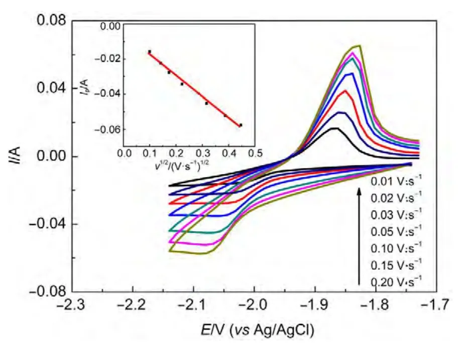
The cyclic voltammograms with various scan rates were obtained on a W electrode in the LiCl-KCl-DyCl3melts at 773 K(see Fig.2).The cathodic peak potential and anodic peak potential shift slightly in the negative and positive direction with the increase of scan rate,respectively.Subsequently,the investigation of the potential scan rate influence on the peak current was performed.Inset in Fig.2 shows the linear relationship between the reduction peak current and the square root of the scan rate,proving that the electrochemical reduction process is controlled by the Dy(III)ions diffusion in the melts.

Fig.2 Cyclic voltammograms obtained in the LiCl--KCl--DyCl3 melts at different scan rates on a W electrode(S=0.322 cm2)at 773 K
3.1.2 Square wave voltammetry
The square wave voltammetry technique was used to determine the number of electrons involved in the electrochemical step.For a simple reversible reaction,the width of the half-peak,W1/2,depends on the number of electrons exchanged and on the temperature as follows:23

where R is the universal gas constant(J·mol-1·K-1),T is the absolute temperature(K),n is the number of exchanged electrons,and F is theFaraday'sconstant(96485 C·mol-1).
Fig.3 shows square wave voltammograms obtained at a step potential of 1 mV and frequency of 30 Hz in the LiCl-KCl-DyCl3(2.50×10⁻⁴mol·cm-3)melts on W and Ni electrodes,respectively.The inset of Fig.3 presents a square wave voltammogram on a W electrode,the peak exhibits an asymmetrical Gaussian signal attributed to the nucleation overpotential.The rise of the current is delayed by the overpotential caused by the solid phase formation.From Refs.23,24 the Eq.(1)can be utilized to calculate the number of electrons involved in the reduction reactions of Dy(III)/Dy(0)when we applied this technique at low frequencies and small step potentials.Using this methodology,the value of n is 2.92,close to three electrons.The result shows that the Dy(III)ions are reduced via a one-step reduction mechanism in the LiCl-KCl melts.
Since the current of cathodic peak E is too small to be observed in Fig.1,and square wave voltammetry is more sensitive and has a higher resolution than cyclic voltammetry,25the square wave voltammetry was employed to further investigate the electrochemical behavior of Dy(III).The square wave voltammogram obtained on a Ni electrode(Fig.3)exhibits four peaks B,C,D,and E,corresponding to the reactions of Dy(III)/Dy(0),the formation of three different intermetallic compounds,respectively.The result is consistent with those obtained from cyclic voltammogram on a Ni electrode.The reduction peak of E is not clear in Fig.1,but it can be observed clearly in Fig.3.

Fig.3 Square wave voltammogram of the LiCl--KCl--DyCl3melts obtained on W(inset)and Ni electrodes(S=0.322 cm2)at 773 K
3.1.3 Open circuit chronopotentiometry
Open circuit chronopotentiometry was carried out to further investigate the formation of Dy-Ni intermetallic compounds.Since the deposited Dy metal reacts with Ni and diffuses into the Ni electrode,the formation of Dy-Ni intermetallic compounds reduce the activity of Dy in the Ni electrode,which resulting in the electrode potential gradually shifts to more positive values.During this process,a potential plateau is observed when the composition of the electrode surface is within a range of a twophase coexisting state.Fig.4 shows an open circuit chronopotentiogram after potentiostatic electrolysis at-2.30 V(vs Ag/AgCl)for 30 s on a Ni electrode.Five potential plateaus were observed at-2.21,-1.98,-1.84,-1.65,and-1.03 V(vs Ag/AgCl),respectively.The plateaus A and B are considered to ascribe to the Li(I)/Li(0)and Dy(III)/Dy(0)potentials,respectively.After that,three plateaus C,D,and E correspond to the coexisting states of different Dy-Ni intermetallic compounds.According to the results of XRD and SEM-EDS in Section 3.2,we speculated that plateaus C,D,and E corresponded to equilibrium reactions are DyNi2⇌Dy2Ni7,Dy2Ni7⇌DyNi5,and DyNi5⇌Ni,respectively,as shown in Fig.4.

Fig.4 Open circuit chronopotentiogram of LiCl--KCl--DyCl3(2.50×10--4mol·cm--3)melts on a Ni electrode(S=0.322 cm2)at--2.3 V(vsAg/AgCl)for 30 s at 773 K

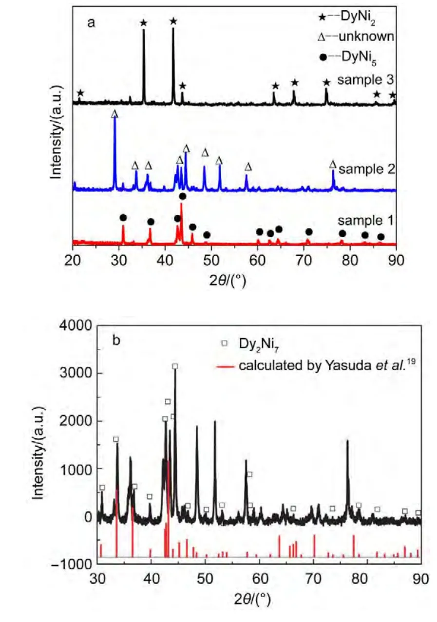
Fig.5 (a)XRD patterns of the deposits obtained by potentiostatic electrolysis in the LiCl--KCl--DyCl3melts on a Ni electrode at 773 K;(b)comparision of diffraction peaks of the sample 2 and those calculated by Yasuda et al.18

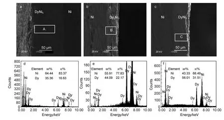
Fig.6 SEM--EDS analyses of the Dy--Ni alloys obtained by potentiostatic electrolysis in the LiCl--KCl--DyCl3melts
3.2 Potentiostatic electrolysis and characterization of the deposits
Based on the results of cyclic voltammogram,square wave voltammogram,and open circuit potentiogram,the Dy-Ni alloy compounds were prepared by potentiostatic electrolysis at selective potential on a Ni electrode(S=2.88 cm2)in the LiCl-KCl-DyCl3(2.50×10⁻⁴mol·cm-3)melts.Fig.5a shows the XRD patterns of Dy-Ni alloy samples obtained by potentiostatic electrolysis at-1.6 V(10 h,sample 1),-1.8 V(10 h,sample 2)and-2.0 V(5 h,sample 3),respectively.XRD patterns indicate that the Dy-Ni alloy samples 1 and 3 are comprised of DyNi5and DyNi2,respectively.Since the JADE 5.0 software does not provide enough data for parsing the XRD source data of sample 2,the diffraction peaks of sample 2 are marked by“unknown”in Fig.5a.Yasuda et al.19calculated the XRD patterns of Dy-Ni intermetallic compounds on the basis of the crystallographic parameters.Fig.5b presents the comparison of the XRD patterns of sample 2 with those calculated by Yasuda et al.19The diffraction peaks are in agreement with those of Dy2Ni7calculated by Yasuda et al.,indicating that the obtained XRD pattern can be attributed to the Dy2Ni7phase.
Fig.6 shows a group of SEM and EDS images of the Dy-Ni alloy samples obtained by potentiostatic electrolysis at-1.6,-1.8,and-2.0 V,respectively.As shown in Fig.6(a,b,c),the compact Dy-Ni alloy layers with good adherence could be prepared.The EDS point analyses of labeledA,B,and C in Fig.6(a,b,c)indicate that the atomic ratios of Ni and Dy are close to 5:1,7:2,and 2:1,respectively(Fig.6(d,e,f)).According to the Dy-Ni phase diagram,26XRD patterns,and analysis of EDS,we think that the Dy-Ni alloy layers are a uniform DyNi5,Dy2Ni7,and DyNi2,respectively.
4 Conclusions
The electrochemical behavior of Dy(III)in the eutectic LiCl-KCl melts on W and Ni electrodes were investigated by a series of electrochemical techniques.The results show that the electrochemical reduction process is controlled by the Dy(III)ion diffusion in the melts.The under-potential deposition of Dy(III)on a Ni electrode is due to the formation of different Dy-Ni intermetallic compounds.According to the results of cyclic voltammograms,square wave voltammogram,and open-circuit chronopotentiograms,the Dy-Ni alloys were obtained by potentiostatic electrolysis at different potential.The Dy-Ni intermetallic compounds,Dy2Ni7,DyNi5,and DyNi2were analyzed by XRD,SEM-EDS.The results indicate that the different Dy-Ni compounds can be selectively prepared by potentiostatic electrolysis.
(1) Yaropolov,Y.L.;Andreenko,A.S.;Nikitina,S.A.;Agafonovb,S.S.;Glazkovb,V.P.;Verbetskya,V.N.J.Alloy.Compd.2011,509,S830.
(2) Edelman,I.;Ovchinnikov,S.;Markov,V.;Kosyrev,N.;Seredkin,V.;Khudjakov,A.;Bondarenko,G.;Kesler,V.Physica B 2008,403,3295.doi:10.1016/j.physb.2008.04.018
(3) Li,J.H.;Liu,B.Z.;Han,S.M.;Hu,L.;Zhu,X.L.;Wang,M.Z.Acta Phys.-Chim.Sin.2011,27(2),403.[李金华,刘宝忠,韩树民,扈 琳,朱惜林,王明智.物理化学学报,2011,27(2),403.]doi:10.3866/PKU.WHXB20110206
(4) Li,P.;Li,Q.Q.;Jin,T.;Zhou,Y.Z.;Li,J.G.;Sun,X.F.;Zhang,Z.F.Mater.Sci.Eng.A 2014,603,84.doi:10.1016/j.msea.2014.02.073
(5) Bermejo,M.R.;Gomez,J.;Martinez,A.M.;Barrado,E.;Castrillejo,Y.Electrochim.Acta 2008,53,5106.doi:10.1016/j.electacta.2008.02.058
(6) Kobayashi,S.;Kobayashi,K.;Nohira,T.;Hagiwara,R.;Oishi,T.;Konishic,H.J.Electrochem.Soc.2011,158(12),E142.
(7) Yasuda,K.;Kobayashi,S.;Nohira,T.;Hagiwara,R.Electrochim.Acta 2013,92,349.doi:10.1016/j.electacta.2013.01.049
(8) Chamelot,P.;Massot,L.;Hamel,C.;Nourry,C.;Taxil,P.J.Nucl.Mater.2007,360,64.doi:10.1016/j.jnucmat.2006.08.015
(9) Iida,T.;Nohira,T.;Ito,Y.Electrochim.Acta 2001,46,2537.doi:10.1016/S0013-4686(01)00470-4
(10) Nohira,T.;Kambara,H.;Amezawa,K.;Ito,Y.J.Electrochem.Soc.2005,152(4),C183.
(11) Iida,T.;Nohira,T.;Ito,Y.Electrochim.Acta 2003,48,1531.doi:10.1016/S0013-4686(03)00031-8
(12)Han,W.;Sheng,Q.N.;Zhang,M.L.;Li,M.;Sun,T.T.;Liu,Y.C.;Ye,K.;Yan,Y.D.;Wang,Y.C.Metall.Mater.Trans.B 2014,45,929.doi:10.1007/s11663-013-9984-8
(13)Sato,K.;Yosida,Y.;Isikawa,Y.;Mori,K.J.Magn.Magn.Mater.1986,54-57,467.
(14) Tripathy,S.K.;Suresh,K.G.;Nirmala,R.;Nigam,A.K.;Malik,S.K.Solid State Commun.2005,134,323.doi:10.1016/j.ssc.2005.01.047
(15) Saïla,A.;Gibilaro,M.;Massot,L.;Chamelot,P.;Taxil,P.;AffouneA.M.J.Electroanal.Chem.2010,642,150.doi:10.1016/j.jelechem.2010.03.002
(16) Kobayashi,S.;Nohira,T.;Kobayashi,K.;Yasuda,K.;Hagiwara,R.;Oishi,T.;Konishi H.J.Electrochem.Soc.2012,159(12),E193.
(17)Tong,Y.X.;Liu,G.K.;Yang,Q.Q.;Hong,H.C.;Chen,S.Y.;Gan,L.J.Rare Earths 1996,14(4),271.
(18)Tong,Y.X.;Liu,G.K.;Yang,Q.Q.;Hong,H.C.;Chen,S.Y.;Gan,L.Rare Metals 1996,15(4),252.
(19)Yasuda,K.;Kobayashi,S.;Nohira,T.;Hagiwara,R.Electrochim.Acta 2013,106,293.doi:10.1016/j.electacta.2013.05.095
(20) Konishi,H.;Nohira,T.;Ito,Y.Electrochem.Solid-State Lett.2002,5,B37.
(21) Konishi,H.;Nohira,T.;Ito,Y.J.Electrochem.Soc.2001,148(7),C506.
(22) Sangster,J.;Pelton,A.D.J.Phase Equilibrium 1991,12,203.doi:10.1007/BF02645715
(23) Bard,A.J.;Faulkner,L.R.Electrochemical Methods:Fundamental and Applications;John Wiley&Sons,Inc.:New York,2001;pp 293-298.
(24) Castrillejo,Y.;Fernández,P.;Bermejo,M.R.;Barrado,E.;Martínez,A.M.Electrochim.Acta 2009,54,6212.doi:10.1016/j.electacta.2009.05.095
(25) Strycker,J.D.;Westbroek,P.;Temmerman,E.Electrochem.Commun.2002,4,41.doi:10.1016/S1388-2481(01)00273-9
(26) Li,M.;Han,W.Calphad 2009,33,517.doi:10.1016/j.calphad.2009.03.004
