A Novel Thermally Coupled Reactive Distillation Column for the Hydrolysis of Methyl Acetate
2015-06-22ZhaiJianLiuYuliangSunLanyiWangRujun
Zhai Jian; Liu Yuliang; Sun Lanyi; Wang Rujun
(1.State Key Laboratory of Heavy Oil Processing, China University of Petroleum, Qingdao 266580; 2. China Petroleum Engineering Co., Ltd., Beijing Company, Beijing 100085)
A Novel Thermally Coupled Reactive Distillation Column for the Hydrolysis of Methyl Acetate
Zhai Jian1; Liu Yuliang1; Sun Lanyi1; Wang Rujun2
(1.State Key Laboratory of Heavy Oil Processing, China University of Petroleum, Qingdao 266580; 2. China Petroleum Engineering Co., Ltd., Beijing Company, Beijing 100085)
A different pressure thermally coupled reactive distillation column (DPT-RD) for the hydrolysis of methyl acetate (MeAc) is developed, and its design and optimization procedures are investigated. The sensitivity analysis is carried out to minimize the energy consumption, which is associated with the total annual cost (TAC). The influence of the proposed DPTRD scheme on energy consumption and economic efficiency are evaluated in comparison with the conventional reactive distillation column (CRD). Both the DPT-RD and CRD are simulated with the Aspen Plus®, and it can be observed that for the DPT-RD the energy consumption and the TAC are reduced, and the thermodynamic efficiency is increased as compared with the CRD process.
different pressure thermally coupled distillation; reactive distillation; thermodynamic efficiency; energy savings; total annual cost
1 Introduction
Distillation columns are widely used in the petrochemical process, but they are also well-known for their high energy consumption and low thermodynamic efficiency. As a result, the process intensification becomes an important trend in chemical industry, which can improve process efficiency and decrease energy consumption by linking different separation units together or integrating with other processes[1]. Many kinds of energy integration techniques have been developed, such as the dividing wall column[2-3], the internally heat-integrated distillation column[4-6], the heat pump-assisted distillation column[7-8], etc. The different pressure thermally coupled distillation (DPT-CD) column is an example of internally thermally coupled distillation technology developed to achieve energy conservation[9]. In this technology, a distillation column is divided into two columns operating under different pressures. The top stream from the high-pressure column is used as the heat source for the reboiler of the low-pressure column. In this way, the thermally coupled process is realized. Li, et al.[9]analyzed the energy saving of DPT-CD by taking the separation of propane-propylene and C4hydrocarbons as an example, and found out that upon comparing with ordinary distillation technologies, the energy consumption could be reduced by 92.3% and 87.1% in these two DPT-CD processes, respectively.
Reactive distillation is an innovative process with numerous applications in the petroleum and chemical industries. It combines the reaction and separation operations together, which can reduce the energy consumption and capital costs[10-11]. This technique is specifically applied to the equilibrium-limited reactions such as esteri fication and ester hydrolysis reactions. The conversion rate can be increased far beyond what is expected due to the continuous removal of reaction products from the reactive zone. Researchers’ results[12-13]showed that reactive distillation has great economic and environmental advantages. Gao Xin, et al.[14]proposed a new process based on the catalytic distillation for MeAc hydrolysis, and the energy saving for this process is 28.6%. Fuchigami[15]applied reactive distillation to the hydrolysis of MeAc by using reactive column packing made of ion-exchange resin molded with polyethylene powder in a furnace, investigated the in fluence of operating variables on the conversion of MeAc, and finally found out that the total energy requirement of
the optimum process was only about 50% as much as that of the conventional process. Han, et al.[16]proposed adding a pre-reactor before the reactive distillation column, and got a great improvement in MeAc throughput compared with the traditional process. Lee, et al.[17]proposed a novel process for MeAc hydrolysis, in which the reflux drum of the distillation column was used as the fixed bed reactor packed with solid acid catalysts.
The different pressure thermally coupled reactive distillation column (DPT-RD) proposed in this article combines DPT-CD and reactive distillation to form a new process intensification technology. Gao Xin and coworkers[18]investigated this novel configuration in the process for tert-amyl methyl ether synthesis. The results showed that the total annual cost (TAC) of this process was by about 6.6% lower than the conventional reactive distillation column (CRD) process. As a typical ester hydrolysis reaction, the hydrolysis of MeAc is investigated in this paper. The design and optimization procedures of the DPT-RD proposed are evaluated and the thermodynamic efficiency and economic performance of the DPTRD are studied.
2 Process Description
2.1 Conventional reactive distillation column
Upon considering the conversion of MeAc and the need of subsequent separation process, the process flow diagram in Figure 1 is supposed as the conventional process in this work.

Figure 1 Conventional reactive distillation process for MeAc hydrolysis
The CRD column has 27 stages, which can be divided into three sections, namely the rectifying section, the stripping section and the reactive section (6thto 17thstage). The separation occurs in all sections. In the reactive section, the MeAc hydrolysis reaction takes place:

The reaction is rate controlled with a liquid holdup of 0.063 m3in the reactive section. The NKC-9 ion exchange resin is chosen as the catalyst, and Quan Xia, et al.[19]provided the reaction kinetics equations which are shown as follows:
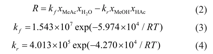
where R is the reaction rate, L/(mol·h); xiis the molar fraction of component i; and kfand krare reaction kinetic constants of the forward and reverse reaction, respectively, L/(mol·h). The reactive section is packed with acid catalyst. The assumptions are made as follows: the catalyst loading occupies half of the tray holdup volume, and the tray holdup is determined by assuming a weir height of 50 mm with a tray spacing of 0.6 m.
A mixture of MeAc and methanol (65:35 in molar ratio) is fed to the bottom of reactive zone with a flow rate of 76.92 kmol/h, and water is routed to the top of column with a flow rate of 250 kmol/h. The vapor condensed at the top of the column is totally recycled. The reflux ratio (reflux ratio=FL/FDas shown in Figure 2) of the CRD is specified at 10 and the top stage/condenser pressure is 0.112 1 MPa with a stage pressure drop of 0.000 7 MPa. The flow sheet of CRD implemented in the Aspen Plus is shown in Figure 2, and Table 1 gives its design parameters.
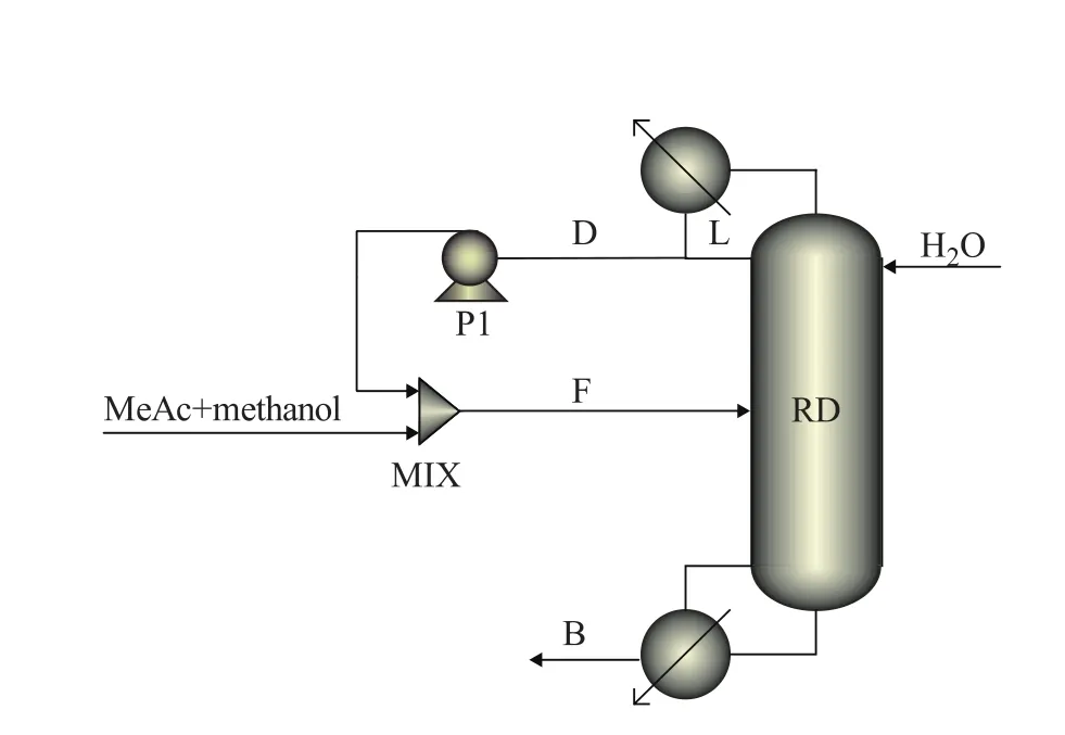
Figure 2 Flow sheet of CRD implemented in Aspen Plus
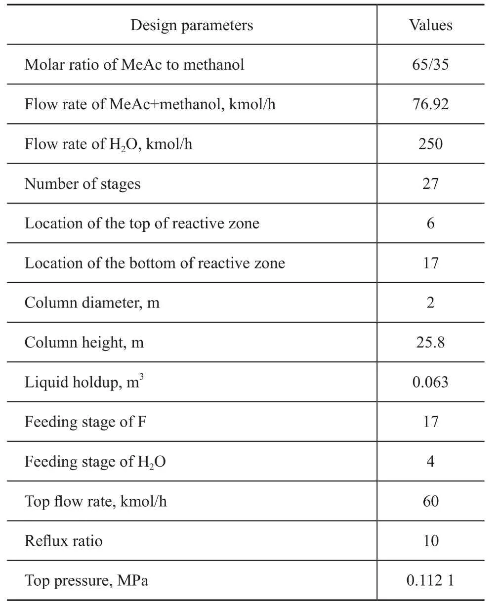
Table 1 Design parameters of CRD
2.2 Different pressure thermally coupled reactive distillation column
DPT-RD contains an atmospheric column and a column with higher pressure. As the hydrolysis of MeAc is an endothermic reaction, high pressure and temperature is in favor of positive reaction, and a configuration of the reaction taking place in the high-pressure column is chosen in this work. The model of DPT-RD in the platform of the Aspen Plus is shown in Figure 3. DPT-RD mainly contains a high-pressure column (T1), a low-pressure column (T2), a compressor (COMPR), a main heat exchanger (HE1), an assisted reboiler (HE3) and an assisted condenser (HE2). The reactive zone of DPT-RD is wholly placed in the high-pressure column (T1).
The feedstocks and products of DPT-RD are identical with CRD to keep the comparability of the two processes. The design parameters of DPT-RD are detailed in Table 2. In this study, the split fractions of splitters SP1 and SP2 are defined as

where FT1D-CR, FT1D-1, FT2B-P, and FT2Bare the flow rate of T1D-CR, T1D-1, T2B-P and T2B in Figure 3, respectively.
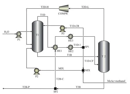
Figure 3 Flow sheet model of DPT-RD implemented in Aspen Plus
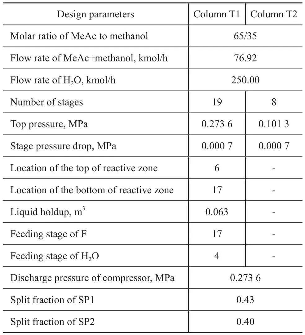
Table 2 Design parameters of DPT-RD
3 Design and Simulation
There are three steps for the development of DPT-RD: shortcut design, rigorous simulation and optimization. The design method of the DPT-RD is based on the CRD. The feed conditions, product specifications and column operating conditions are available from either the plant or the given examples depending on the situation.
The simulation of the DPT-RD is carried out using the rigorous distillation module RadFrac of Aspen Plus®. The UNIQUAC method is adopted for the calculation of the activity coefficients in liquid phase and the Hayden-O’Conell equation of state is used to describe the vapor phase behavior. The predicted azeotropic temperatures and compositions agree well with experimental results[20], as shown in Table 3.
The shortcut design of the DPT-RD can be obtained by dividing a CRD into two columns with different pressures and by exchanging heat between the top stream from the high-pressure column and the bottom stream of the lowpressure column. And a compressor is adopted to provide the upward vapor for the high-pressure column.
The RadFrac module of Aspen Plus®, a rigorous model for simulating all types of multistage vapor-liquid fractionation operations, is selected for the simulation of the flowchart as shown in Figure 3. The UNIQ-HOC physicalproperty method is adopted when the simulation is implemented using the Aspen Plus. Rigorous simulation used in the present study is based on the equilibrium-stage model, which uses the mass, equilibrium, summation of molar fractions and enthalpy (MESH) equations for each stage. The stage numbers of the whole column and reaction section in DPT-RD are the same as those of CRD respectively, with the purpose of comparing the performance of the two processes. And for both of DPT-RD and CRD, the stages are numbered in a downward direction.

Table 3 Properties of azeotropic mixtures obtained during hydrolyzation of MeAc
According to the features of DPT-RD (Figure 3), many sensitivity tests have been carried out in the optimization process to adjust the design and operating variables. Here, the design variables considered are the top pressure of T1, the compression ratio, the feeding stages of water and MeAc, the split fraction of SP1, and the split fraction of SP2. By keeping the input conditions identical for both distillation schemes, the variables of the DPT-RD are systematically adjusted to obtain the conditions that meet the product specifications.
3.1 Selection of top pressure of T1
Here, the heat transfer temperature difference refers to the difference between the top temperature of T1 and the bottom temperature of T2. Only after the heat transfer temperature difference reaches a specific value, the DPTRD then can operate effectively, which is very crucial for the good performance of DPT-RD. Figure 4 illustrates how the top pressure of T1 affects the heat transfer temperature difference of DPT-RD. It shows that, along with the increase in the top pressure of T1, the top temperatureof T1 would increase while the bottom temperature of T2 remains nearly unchanged, and the temperature difference would enlarge finally. When the heat duty keeps constant, the heat-exchange area should increase with the reduction of the temperature difference. Upon considering the cost of heat exchanger and the normal operation of DPT-RD, the top pressure of T1 was set at 0.233 0 MPa.

Figure 4 Effect of pressure on heat transfer temperature difference
3.2 Selection of compression ratio
The influence of compression ratio on product purity and energy consumption of DPT-RD is presented in Figure 5 with other variables remaining unchanged. Obviously, as the compression ratio increases, the molar fraction of MeAc in the product stream drawn from the bottom of T2 slightly decreases. However, the energy consumed by the compressor significantly increases with an increasing compression ratio. Finally, the compression ratio is selected as 2.5 to meet the product specification.

Figure 5 Effect of compression ratio on product purity andenergy consumption
3.3 Selection of feeding stage of water
The influence of the feeding stage of water on the product purity and energy consumption is displayed in Figure 6. This simulation experiment is performed with the values of other variables fixed. It can be concluded that the feeding stage of water has little impact on product purity and energy consumption. The 6th stage (numbered from top downward) is chosen as the stage of water feeding, where the molar fraction of MeAc in product stream and the compressor duty would change relatively quickly.

Figure 6 Effect of feeding stage of water on product purity and energy consumption
3.4 Selection of feeding stage of MeAc and methanol
The feeding stage of MeAc and methanol has been varied from 8th to 19th (numbered from top downward), while the values of other variables remain the same as those shown in Table 3. Figure 7 shows how the feeding stage of MeAc and methanol affects the product purity and energy consumptionof DPT-RD. Both of the molar fraction of MeAc and the compressor duty nearly remain constant before the feeding stage moves to the 16th stage, but when the feeding stage continues to move downward, the compressor consumes more energy and the product purity drops sharply. The stream of MeAc and methanol is fed at 16th stage hereupon to achieve the desired product purity in this work.
3.5 Selection of split fraction of SP1
Figure 8 shows the effect of split fraction of SP1 on product purity and energy consumption, with other variables remaining constant. It’s clear that, when the split fraction of SP1 increases, the product purity also increases, but the energy consumption increases constantly as well. This happens because of the increase in the flow rates inside the column. To save energy as much as possible, the split fraction of SP1 is chosen as 0.43.
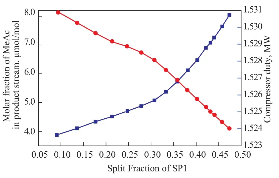
Figure 8 Effect of split fraction of SP1 on product purity and energy consumption
3.6 Selection of split fraction of SP2
The top pressure of T1, the compression ratio, the feeding stage of water, the feeding stage of MeAc and methanol, and the split fraction of SP1 are specified at 0.233 0 MPa, 2.5, 4, 17, and 0.43, respectively, as required by the test process. When the split fraction of SP2 varies, the corresponding product purity and energy consumption profiles are presented in Figure 9. As the split fraction of SP2 increases, the product purity at first remains unchanged and then drops quickly, while the energy consumption decreases continuously. This happens because the hydrolysis of MeAc is an equilibrium-limited reaction, and the continuous removal of reaction products facilitates the conversion of MeAc. From this sensitivity test, the split
另外,美国“河网”组织于2009年10月26日举办了主题为“节约用水,节约能源:应对气候变化和保护河流的综合方法”的研讨会,其主要议题就是水—能、节水和节能的关系。相信随着全球气候变化导致的水资源供给不稳定性加剧以及能源紧缺,该领域将会成为未来的一个研究热点。

Figure 9 Effect of split fraction of SP2 on product purity and energy consumption
fraction of SP2 can be selected as 0.55. Based on the aforementioned work, the optimum parameters of DPT-RD for the hydrolysis of MeAc can be obtained, and the simulation results of DPT-RD under optimal conditions are shown in Table 4.
4 Results and Discussions
There are manyReferences for the calculation of thermodynamic efficiency and total annual cost (TAC)[21-22]. The thermodynamic analysis results and TAC of CRD and DPT-RD for the hydrolysis of MeAc are summarized in Table 5.It can be seen that the CRD requires a heat duty of 7 062.3 kW while the energy consumption of the DPT-RD is 2 441.1 kW, which shows that the DPT-RD can save the energy by 36.1% compared to the CRD. The total heat transfer area of the reboilers of the CRD is 357.3 m2, while that of the DPT-RD is 149.3 m2, which can achieve a reduction of 58.2%. The reduction in total heat transfer area of the condensers is about 90.6% with the value equating to 560.6 m2for the CRD and 54.1 m2for the DPT-RD, respectively. The capital cost investment for the DPT-RD is increased compared to the CRD because of the expensive cost of compressor used in the DPT-RD. As regards the operating cost aspects, the CRD requires both a bottom reboiler and a top condenser, whereas DPT-RD could omit the bottom reboiler. Hence, the operating cost for the DPT-RD is relatively low. As a result, compared to the CRD, the TAC for the DPT-RD is decreased by about 41.3% over a period of 5 years of plant life time with the value equating to 2 238.2×10³$/a for the CRD and 1 314.0×10³$/a for the DPT-RD, respectively. Besides, the thermodynamic efficiency is enhanced by 2.9%. According to the above analysis, it is obvious that the DPT-RD is an economic option and can save much energy and TAC for the hydrolysis of MeAc.
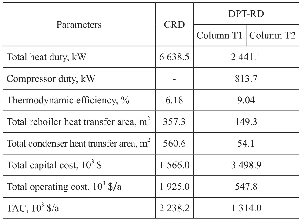
Table 5 Thermodynamic analysis results and TAC of CRD and DPT-RD for the hydrolysis of MeAc
5 Conclusions
In this study, the hydrolysis of MeAc is studied using a CRD and a different pressure thermally coupled reactive distillation column (DPT-RD). The design configuration and optimization of this technology are investigated. The optimal design flow sheet of DPT-RD is obtained by minimizing the total energy consumption of the process by means of the sensitivity analysis. The results show that the proposed DPT-RD can achieve significant energy savings and improve the thermodynamic efficiency by around 2.9%, and its TAC is reduced by 41.3% in comparison with the CRD. Obviously, the DPT-RD provides advantages in terms of higher energy savings and a lower TAC.
Acknowledgements: This work was supported by the National Natural Science Foundation of China (Grant Nos. 21276279, 21476261); the Key Technologies Development Project of Qingdao Economic and Technological Development Zone (Grant No. 2013-1-57); the Fundamental Research Funds for the Central Universities (No. 14CX05030A; No. 14CX06108A). Furthermore, the authors are grateful to the editor and the anonymous reviewers for their helpful comments and constructive suggestions with regard to the revision of the paper.
[1] R eay D. The role of process intensification in cutting greenhouse gas emissions[J]. Applied Thermal Engineering, 2008, 28(16): 2011-2019
[2] M ueller I, Kenig E Y. Reactive distillation in a dividing wall column: Rate-based modeling and simulation[J]. Industrial & Engineering Chemistry Research, 2007, 46(11): 3709-3719
[3] P remkumar R, Rangaiah G P. Retrofitting conventional column systems to dividing-wall columns[J]. Chemical Engineering Research and Design, 2009, 87(1): 47-60
[5] N akaiwa M, Huang K, Endo A, et al. Internally heatintegrated distillation columns: A review[J]. Chemical Engineering Research and Design, 2003, 81(1): 162-177
[6] Naito K, Nakaiwa M, Huang K, et al. Operation of a bench-scale ideal heat integrated distillation column (HID-iC): an experimental study[J]. Computers & Chemical Engineering, 2000, 24(2-7): 495-499
[7] Gadalla M, Olujić Ž, De Rijke A, et al. Reducing CO2emissions of internally heat-integrated distillation columns for separation of close boiling mixtures[J]. Energy, 2006, 31(13): 2409-2417
[8] Annakou O, Mizsey P. Rigorous investigation of heat pump assisted distillation[J]. Heat Recovery Systems and CHP, 1995, 15(3): 241-247
[9] Li H, Li X, Luo M. Different pressure thermally coupled distillation technology for energy saving [J]. Chemical Industry and Engineering Progress, 2008, 27(7): 1125-1128
[10] Luyben W L, Yu C C. Reactive Distillation Design and Control[M]. Wiley-AIChE, 2008
[11] Sundmacher K, Kienle A. Reactive Distillation: Status and Future Directions[M]. Wiley-VCH, 2006
[12] Taylor R., Krishna R. Modelling reactive distillation[J]. Chemical Engineering Science, 2000, 55(22): 5183-5229
[13] Malone M F. Reactive distillation[J]. Industrial & Engineering Chemistry Research, 2000, 39(11): 3953-3957
[14] Gao X, Li X, Li H. Hydrolysis of methyl acetate via catalytic distillation: Simulation and design of new technological process[J]. Chemical Engineering and Processing: Process Intensification, 2010, 49(12): 1267-1276
[15] Fuchigami Y. Hydrolysis of methyl acetate in distillation column packed with reactive packing of ion exchange resin[J]. Journal of Chemical Engineering of Japan, 1990, 23(3): 354-359
[16] Han S J, Jin Y, Yu Z Q. Application of a fluidized reaction-distillation column for hydrolysis of methyl acetate[J]. Chemical Engineering Journal, 1997, 66(3): 227-230
[17] Lee M K, Kim T J. Method and apparatus for hydrolyzing methyl acetate: KR, 2000072037[P], 2000-12-05
[18] Gao X, Wang F Z, Li H., et al. Heat-integrated reactive distillation process for TAME synthesis[J]. Separation and Purification Technology, 2014, 132: 468-478
[19] Quan X, Chen X, Wei K. Kinetics of the hydrolysis of methyl acetate catalyzed by NKC-9 cation-exchange resin[J]. Industrial Catalysis, 2006, 14(10): 31-35 (in Chinese)
[20] Gmehling J, Menke J, Krafczyk J, et al. Azeotropic Data, Volume 3[M]. VCH Verlag, Weinheim, 2004
[21] Mane A, Jana A K. A new intensified heat integration in distillation column[J]. Industrial & Engineering Chemistry Research, 2010, 49(19): 9534-9541
[22] SunlY, Chang X W, Qi C X, et al. Implementation of ethanol dehydration using dividing-wall heterogeneous azeotropic distillation column[J]. Separation Science and Technology, 2011, 46(8): 1365-1375
date: 2014-12-14; Accepted date: 2015-04-06.
Professor Sun Lanyi, Telephone: +86-13854208340; Fax: +86-532-86981787; E-mail: sunlanyi@upc.edu.cn.
猜你喜欢
杂志排行

中国炼油与石油化工的其它文章
- Pyrolysis Characteristics and Kinetics of Methyl Oleate Based on TG-FTIR Method
- Synthesis of Waterborne Polyurethane Modified by Nano-SiO2Silicone and Properties of the WPU Coated RDX
- A Highly Efficient and Selective Water-Soluble Bimetallic Catalyst for Hydrogenation of Chloronitrobenzene to Chloroaniline
- Curing Mechanism of Condensed Polynuclear Aromatic Resin and Thermal Stability of Cured Resin
- A Mathematical Model Based on Supply Chain Optimization for International Petrochemical Engineering Projects
- Effects of Fe2+, Co2+and Ni2+Ions on Biological Methane Production from Residual Heavy Oil