基于微流挤压成型工艺的陶瓷制品挤出过程仿真和优化*
2015-02-26段国林朱东彬
周 婧,段国林,卢 林,朱东彬*
(1.河北工业大学机械工程学院,天津300130;2.天津电气科学研究院有限公司,国家电控配电设备质量监督检验中心,天津300180)
基于微流挤压成型工艺的陶瓷制品挤出过程仿真和优化*
周婧1,段国林1,卢林2,朱东彬1*
(1.河北工业大学机械工程学院,天津300130;
2.天津电气科学研究院有限公司,国家电控配电设备质量监督检验中心,天津300180)
摘要:利用Ansys软件对基于微流挤压成型的陶瓷制品的成形过程进行模拟来指导挤出头的设计。通过分析和计算,陶瓷浆料的流变特性符合宾汉姆流体模型。在确定流体特性的基础上设计出挤出成形的关键部件挤出头,并对影响挤出速率的主要工艺参数压缩角和压缩比进行了研究。通过模拟分析得出挤出速率与压缩角成反比而与压缩比成正比,影响挤出速率的主要工艺参数是压缩比。并将此结果用于指导挤压头的优化设计。
关键词:固体氧化物燃料电池;微流挤压成型;流变学;模拟
项目来源:河北省自然科学基金(E2011508003,E2013202128)
Now available for use of fossil fuels is dried up,and the traditional fossil energy will bring a lot of pollution in the process of using.Solid oxide fuel cell (SOFC ) as a kind of new energy whose energy conversion rate is high and the environmental friendly,relieve the strain on the energy and environmental problems.It is the most efficient device having been invented which has the chemical energy into electric energy directly.It is not limited by carnot cycle,clean,low noise,high energy conversion efficiency.SOFC is considered as alternative internal combustion engine power plant by the international energy industry[1-4].
Currently structure type of applied research more extensive is divided into plate type SOFC and tubular SOFC.The tubular SOFC has two types:Large diameter(>15 mm) tubular battery and small diameter(<5 mm) micro-tubular battery.Micro-tubular solid oxide fuel cell can reduce the volume of the SOFC,the miniaturization structure obviously improves the mass transfer,heat transfer and reaction efficiency,which can realize the rapid start up and shut down,easy to move and carry.Therefore SOFC miniaturization research is more andmore taken seriously,to become an international research hotspot.In the early 90 s,Kendall et al[5-6]made the tubular solid oxide fuel cell for the first time using about 1 mm in diameter of YSZ microtubules as support,and the electrochemical properties were tested.Since then,the micro-tubular solid oxide fuel cell in the preparation and structure design have got a rapid development[7].This article mainly discussed the key preparation technology of micro-tubular solid oxide fuel cell and so on.
1 The Preparation Technology of Solid Oxide Fuel Cell and Material Properties
The electrolyte of SOFC mainly adopts yttria stabilized zirconia (YSZ) material.The anode materials is nickel metal ceramic material.The cathode material is doped manganese acid lanthanum ceramic powder.Battery connection body is mainly composed of chromic acid lanthanum.These materials are typical non-metallic ceramic powder.According to the material properties we can apply the typical ceramic extrusion forming technology to manufacture SOFC.Withthe vigorous development of the micro/nano science and technology,adopting micro-flow extrusion forming process to prepare small size SOFC electrolyte tube can get good ionic conductivity and air tightness.Jonathan Powell and Stuart Blackburn[8],professorsattheuniversityof Birmingham,UK,adopting micro-flow extrusion forming process to manufacture the micro tubular SOFC successfully.The diameter of battery is 3 mm,wall thickness is 400 μm,as shown in Fig. 1.

Fig. 1 micro-tubules SOFC[8]
One of the key technologies in extrusion forming process is prepare ceramic slurry with low viscosity,high solid content,stable dispersion and good liquidity.SOFC forming slurry is composed of YSZ powder,2-butanone/ ethanol as solvent,polyvinyl butyral as binder,polyethylene glycol (peg) as plasticizing agent,triglyceride as wetting agent.Out of slurry solid content over 44%,it presents a typical non-newtonian fluid phenomena.Common rheological properties of non-newtonian fluid is mainly characterized by different viscosity,through a great deal of experimental research show that the solid phase suspension liquid with the higher volume fraction whose rheological properties conforms to the Bingham fluid properties.Therefore,the viscous paste used for extrusion forming in which nonmetal ceramic powder is given priority to solid material,conforms to the Bingham fluid model.The viscosity model as shown in Eq.(1) :

in whichτis shear stress,γ is shear rate,n is nonnewtonian coefficient[9].
The characteristic of Bingham fluid model related to the flow stress intensity.Under the plastic standard,it presents rigid fluid.After more than the plastic standard,the added value of stress is proportional to the strain rate.
2 The Design of Extrusion Head
2.1The design of extrusion head
In extrusion forming process of ceramic slurry,extrusion head is the key part to realize the extrusion forming smoothly,which have a strong impact on the surface quality of the extrusion forming products and forming precision,so design and optimization of the extrusion head have important theoretical significance and practical value.In the design of extrusion head,there are two key principles,one is to ensure that each function section smooth transition,that can avoid materials decomposition caused by ceramic slurry in the extrusion flow channel stagnation or not free flow; The other one is to ensure the slurry flow balance,mainly to ensure forming slurry flow velocity is consistent with the average flow velocity on the exit cross section of extrusion head,which can guarantee the precision of extrusion products.
A complete extrusion head mainly includes five functional sections:drainage section,shunt section,straight section,compression section and extrusion section.Driven by the pressure of piston,ceramic slurry via every function section of extrusion head,gradually formed the shape we need.The shape and size of theflow channel determine the flow behavior of ceramic slurry and the pressure distribution of flow passage wall.All of these factors have a crucial impact on the quality of the product.Based on the above factors,the circular seam type extrusion head was designed.Fig. 2 is the structure diagram of circular seam type extrusion head. Circular seam type extrusion head is mainly used in preparing thin wall of micro-tubular SOFC,which could use for tubular battery monomer a one-time preparation in the process of actual production,thus avoiding the path planning work in the rapid prototyping,reducing the workload and improving the speed of preparation.
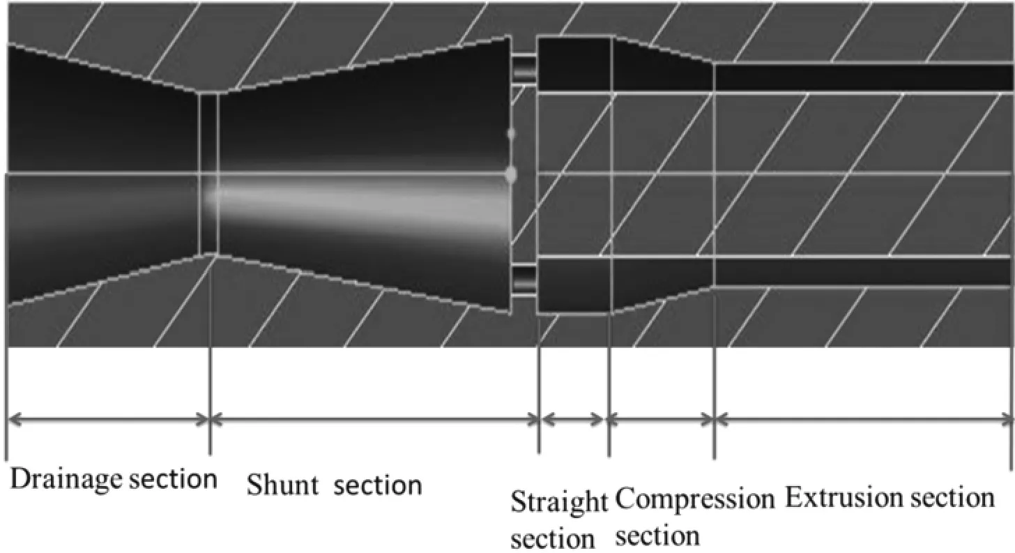
Fig. 2 The structure diagram of circular seam type extrusion head
2.2The influence on extrusion forming of each functional section
Drainage section make the flow direction of ceramic slurry convergence through cracks mode,it can make the circumferential flow of the slurry in the flow pass into the axial flow,by the turbulent flow into laminar flow.The change of ceramic paste flow properties can make the forming more stable.Shunt section has not a large impact on the quality and stability of squeeze material,its goal is to achieve smooth flow and no material stranded.The role of straight section is to make forming slurry keep stretch as far as possible,smooth flow,reduce the stress concentration,avoid the material properties change.Compression section can form strong convergence flow,which is conducive to make the material dense and make it have high mechanical properties.The role of the perforated plate between the shunt section and flat section is effectively to reduce the melt fracture phenomenon,improve the precision of extrusion,at the same time,it can play a role of sealing and prevent material stranded[10].
3 Micro-Flow Extrusion Forming Process Simulation
The main structure parameters of compression section are compression ratio ε,compression angle β and compression length L.Compression ratio is equal to the entrance cross-sectional area of the forming section than export cross-sectional area.Determination of material compression ratio is related to its characteristic and the product shape.The wall thickness of the tubular SOFC prepared is constant value,compression angle β is controlled at 20°~40°.Compression angle is too big will lead to the flow shape change,which is not conducive to the stable extrusion,while compression angle is too small will be not convenient for production optimization adjustment.The key parameters of compression section,compression angle and compression ratio,which determine the length of the compression section.
The flow equation of non-newtonian fluid in the annular flow as shown in Eq.(2) :

It can be seen that forming slurry flow rate is inversely proportional to the flow channel length L and proportional to the flow channel height Δh.The sizes of the compression ratio and compression angle determine the flow channel length and the height of the extrusion flow channel[11-12].
3.1 Build the finite element model
Due to the axial symmetry of the circular seam type extrusion head,it used the two dimensional model to replace the three-dimensional stereogram,and used 1/2 area of extrusion head model instead of the entire flow area.It adopted the finite element software ANSYS to simulate the extrusion forming process.Fig. 3 is the finite element model of forming flow channel after divided into unit.The volume fraction of using the SOFC forming ceramic paste is 50% YSZ slurry,material density is 2972 kg/m3,rheological properties is the Bingham fluid model,keeping the temperature of extrusion forming process is constant 110℃,and viscosity keeping the constant value 300 Pa·s.
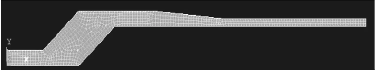
Fig. 3 The finite element model of extrusion head flow channel
3.2Set up simulation boundary conditions
With reference to the principle of no slip wall in extrusion process,in addition to the exit and the entrance of the extrusion head,the velocity component of the boundary surface between the extrusion mold and the forming ceramic slurry is zero.According to the processing conditions,extrusion pressure is 80 MPa,slurry flow velocity at the entrance is 1 inch/s,outlet pressure is zero,as a standard atmospheric pressure(101 350 Pa) for reference.As thermodynamic temperature 0 K for the reference temperature,the processing temperature is 423 K(150℃).Thermal conductivity of materials is 1.5 W/(m·K)~2.0 W/(m·K).
3.3Simulation results
In three different compression ratio ε(1.778,1.306,1.778),the change of compression angle β(12.5°,16°,25°) has the influence on pressure and velocity when ceramic slurry flow in extrusion head.When compression angle is 12.5°,the pressure distribution change of extrusion forming in the flow field is more uniform,the characteristic of ceramic slurry can keep relatively stable state,the maximumvelocity of extrusion flow is 0.005 085 m/s.When compression angle is 16°,the analysis result is similar to Fig. 4(a),the flow is normal,uniform pressure distribution,no obvious stress concentration area,and the maximum extrusion forming speed is 0.005 064 m/s.When compression angle is 25°,the maximum velocity in extrusion flow field is 0.005 046 m/s.
Similarly,the flow condition under the different compression ratio is analyzed respectively.When the compression ratio ε=1.306,the biggest flow velocity of extrusion die is 0.001 989 m/s,the flow field distribution as shown in Fig.5.When compression ratio ε=1.138,the maximum velocity of extrusion die is 0.001 576 m/s,the flow field distribution as shown in Fig.6.The maximum velocity when the compression ratio is 1.778,is three times of the value when the compression ratio is 1.138.This shows that the influence of compression ratio on the flow velocity of extrusion forming slurry is very large.

Fig. 4 When compression ratio ε=1.778,compression angle respectively is 12.5°,16°,25°,the flow field analysis diagram
3.4Conclusion of the third section analysis
From the above analysis it can be concluded that:when compression ratio ε is constant,the velocity of extrusion forming is inversely proportional to thecompression angle,in the case of smaller compression angle(less than 25°),the change trend is obvious.Continue to increase β,the change of extrusion flow rate is steady,it can be seen that β is smaller effect on flow velocity.But when compression angle is too big,it can lead to flow channel structure deformation,which reduce the quality of extrusion forming product,and it is not conducive to high precision manufacture.
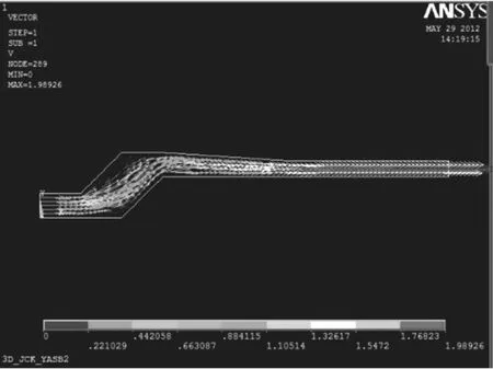
Fig. 5 Flow field velocity scattergram(ε=1.306)
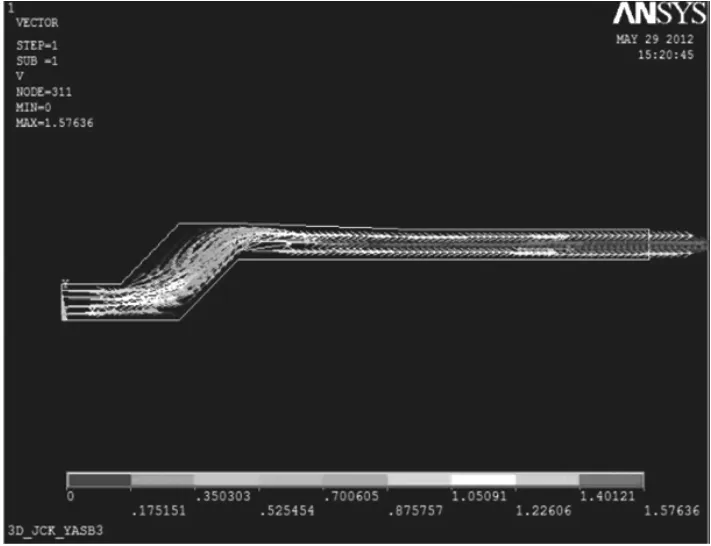
Fig. 6 Flow field velocity scattergram(ε=1.138)
When the compression angle β is constant,the compression ratio is directly proportional to the extrusion die flow velocity,ε increase means straight section length decrease,increasing the flow channel area to reduce the flow resistance,thus it can increase the flow velocity of slurry.Through the contrast can be obtained that there is the largest effect on extrusion flow rate is the compression ratio.
4 Extrusion Head Flow Channel and Process Parameters Optimization
In the optimization and design work of extrusion head,design variables are the geometry parameters of extrusion head,including compression angle,compression ratio and the length of the straight section.Constraints of the optimization equation are flow channel extrusion speed and forming pressure drop.The final optimization objective is to achieve uniform extrusion velocity at export.Related mathematical model is set up as shown in Eq.(3).By adjusting the structure parameters of extrusion head realize high quality and stable extrusion.Based on the rheology theory and APDL parameter optimization design concept,the extrusion head design optimization process is proposed by means of FEM.The optimization design process is shown as Fig.7.

in which f(φ) is objective function,viis the exit velocity at node i,v is average velocity of slurry flow,N is node number of exit unit,φ is variable.

Fig. 7 Optimization flow chart
In the optimization design process of extrusion head,compression ratio ε=1.778,compression angle β= 12.5°as an example,by adjusting the structureparameters of the extrusion head to realize high quality and stable extrusion.The optimized extrusion head velocity compared with the initial value,increased nearly twice as much in terms of evenness.As can be seen from the table 1,compression section length shorten,straight section length increase,at the same time compression angle greaten,which accord with the rational value of compression angle.Optimized extrusion process parameters have promoted on several aspects,including reduce resistance of slurry flow and increase the average velocity at the exit,from 0.005 085 5 m/s increase to 0.005 123 6 m/s,〗increasing the extrusion forming flow per unit time.Fig. 8 show the slurry flow velocity distribution at the exit after the optimization.The pressure distribution of straight section is more even,the stress concentration in good condition,it has a good gradient change,and it can ensure the stability of forming slurry.
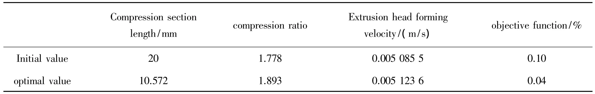
Table 1 Initial value and the optimal value comparison table

Fig. 8 The nephogram of optimized extrusion flow velocity distribution
5 Conclusions
This paper selected micro-flow extrusion forming process for preparing the SOFC monomer,designed the key part in the process of extrusion which was functionalization of extrusion head.Using computational fluid dynamics(CFD) method in the theory of finite element analysis and optimization design theory,it analysis the change of the extrusion head flow channel geometry parameters on the properties of ceramic slurry flow influence law,so as to provide theoretical reference for production practice.Solid oxide fuel cells is still a research focus of energy industry and materials industry,the micro-flow extrusion forming process is also a kind of advanced technology,the study of complex fluid is a system of engineering,there are a lot of work remains to be further.
参考文献:
[1]Liang Liping,Gao Yinben,Chen Songying.Solid Oxide Fuel Cells and Ceramic Materials[J].Journal of Materials Science and Engineering,1997(4) :10-15.
[2]Lu Junbiao,Zhang Zhongtai,Tang Zilong.Review on the Development of Solid Oxide Fuel Cells[J].Rare Metal Materials and Engineering,2005(8) :1177-1180.
[3]Huang Xianliang,Zhao Hailei,Wu Weijiang.Development and Future of Solid Oxide Fuel Cell[J].Journal of The Chinese Ceramic Society,2005(11) :109-115.
[4]Kim-Lohsoontorn P,Priyakorn F,Wetwatana U.Modelling of a Tubular Solid Oxide Fuel Cell with Differentdesigns of Indirect Internal Reformer[J].Journal of Energy Chemistry,2014,23:251-263.
[5]Han Minfang,Yin Huiyan,Tang Xiuling.Development and Future of Solid Oxide Fuel Cell[J].Vacuum Electronics,2005(4) :23-26.
[6]Wang Lixia,Chen Jingbo,Liu Chuntai.Mechanics and Engineering [J].1998,20(2) :17-19.
[7]Jin Yifei,The Rheological Theoriesand Experimental Research on Polymer Micro Extrusion Process[D].Dalian:Dalian University of Technology,2010.
[8]Jonathan Powell,Stuart Blackburn.Co-Extrusion of Multilayered Ceramic Micro-Tubes for Use as Solidoxide Fuel Cells[J].Journal of the European Ceramic Society,2010,30:2859-2870.
[9]Wang Lijin,Zhang Huisheng,Weng Shilie.Modeling and Simulation of High Temperature Direct InternalReforming Solid Oxide Fuel Cell [J].Proceedings of the CSEE,2007,26235:78-83.
[10]Yue Ruifeng,Zeng Xuefeng,Wu Jiangang.Simulation of Digital Microfluidic Device Based on Electrowetting-on-Dielectric[J].Chinese Journal of Electron Devices,2006,29(3) :778-780.
[11]Liu Baosheng,Song Jiupeng,Cheng Zhiqiang.Research on Powder Injection Molding and International Cooperation[J].Journal of Chongqing Institute of Technology:Natural Science,2008,22(11) :31-37.
[12]Jiang zhongbing,Li duxin,Li Kun.Study on Rheological Properties of Feedstock for ZrO2Powder Injection Molding[J].Powder Metallurgy Technology,2009,27(6) :418-421.

周 婧(1983-),女,汉族,河北保定人,博士研究生,研究方向为快速成型,CAD/CAM/RPM,zhoujing0807@126.com;

朱东彬(1975-),男,汉族,河北唐山人,博士,副教授,主要从事快速成型、CAD/CAM/RPM、功能陶瓷等方面的研究,zhu_dongbin@ 163.com。
段国林(1963-),男,汉族,河北保定人,博士,教授,博士生导师,研究方向为现代CAD技术,制造业信息化,glduan@ hebut.edu.cn;
The Study of Optical Properties to Magnetron Sputtering LaB6Film
WU Huajie,LIN Zulun*,WANG Xiaoju,DENG Jiang
(Shool of Optoelectronic Information,University of Electronic Science and Technology of China,Chengdu 610054,China)
Abstract:LaB6films were deposited on glass substrate by magnetron sputtering.The sputtering power parameters were changed for optimal preparation conditions.X-ray diffraction and Spectrometer were used to study structure,transmittance and crystalline phase of the films.The LaB6films had relatively smooth surface,compact structure when deposited at the optimized parameters(sputtering power was 44 W,argon gas pressure was 1.5 Pa,argon gas flow rate was 27 sccm).Results of XRD showed that the LaB6films which deposited at the optimized parameters had high crystallization and distinct(110) preferred orientation.Results of Spectrometer showed that transmittance of the films decreases with increasing sputtering time.And the wavelength corresponding to the maximum transmittance of the films is at the same position.
Key words:magnetronsputtering; lanthanum hexaboridefilm; crystalorientation; transmittance
中图分类号:TQ175.620
文献标识码:A
文章编号:1005-9490(2015) 03-0473-07
收稿日期:2014-12-11修改日期:2014-12-25
doi:EEACC:0520; 411010.3969/j.issn.1005-9490.2015.03.002