Design and test of the magnetorheological dam per of aircraft landing gear*
2014-06-09ShixingZHUMingtaoLUYonggangYANGJingTIANBangCHEN
Shi-xing ZHU,Ming-tao LU,Yong-gang YANG,Jing TIAN,Bang CHEN
School of Aeronautical Engineering,Civil Aviation University of China,Tianjin 300300,China
Design and test of the magnetorheological dam per of aircraft landing gear*
Shi-xing ZHU†,Ming-tao LU,Yong-gang YANG,Jing TIAN,Bang CHEN
School of Aeronautical Engineering,Civil Aviation University of China,Tianjin 300300,China
In order to im prove the performance of the shock absorber of aircraft landing gear and study the application of magnetorheological damping technology in the shock absorption structure of aircraft landing gear,the structure and the working principle of a kind of magnetorheological damper with oil needle is proposed and the structure is designed.The optimization of the magnetic circuit is conducted and finally the damping force characteristic and damping effect have been studied through the vibration test and drop test.The results show that the dam ping characteristic of the shock absorber is good and it has relative large adjustment range for the damping force and good energy dissipation performance.It could change the maximum vertical shock load and the piston displacement of different heights by changing the current.
Magnetorheological damper,Magnetic circuit,Oil needle,Damping characteristics, Drop test
1.Introduction
Shock absorber of aircraft landing gear is an important damping structure of the aircraft,which plays an irreplaceable role in slowing the fuselage vibration,reducing the ground load,improving the ride comfort and ensuring the flight safety.At present,the oil-gas and the passive controlled hydraulic shock absorber was widely applied in landing gear,thought these shock absorber had variable cross-section oil needle,double chamber and pressure valve structure to improve the buffer performance of the shock absorber[1-3],their suspension system only reacts to local corresponding movement,and is restrained by the gear stroke,which restricts the parameter selection and the system parameters could not be adjusted in real time along with the change of ground excitation[4],it could not meet the damping requirement of the aircraft when the aircraft has high speed in taking-off or landing especially in bad conditions,so it is required to adopt more advanced shock absorption technology.In recent decades,magnetorheological damping technology obtained fast development,magnetorheological damper which is based on MRF damping medium had been gradually adopted in automobiles,bridges,buildings,and other areas of the damping[5-6].Since the magnetorheological damper has simple structure,low energy consumption,rapid response and widely damping adjustment,it would greatly improve the damping performance of landing gear if it is applied to aircraft landing gear damping system.
There had not certain magnetorheological damper which was applied on the landing gear,but foreign scholars had studied it and designed the magnetorheological damper which was applied to the landing gear,and published some related research results[7 -9].In domestic,Jia yuhong and others studied the applications of magnetorheological damper on the landing gear and corresponding control algorithm[10-12].Wang Wei,et al.,studied the application of magnetorheological damper of helicopter landing gear in inhibiting ground resonance[13],Tian jing et al.,researched the drop simulation of magnetorheological damper of landing gear[14].Based on the magnetorheological damper of landing gear,a new structure magnetorheological damper was designed. Some related experiments and analysis have been conducted.The results show that this kind of damper has good damping performance and this paper has a certain reference value to the application of magnetorheological damper on the landing gear.
2.The working principle of magnetorheological dam per of landing gear
The structure of the magnetorheological damper of the landing gear is shown in Figure 1,this damper adopts an accumulator as its size compensating element,the wires are leaded through the hollow piston rod and its principle diagram in the landing gear of experimental prototype is shown in Figure 2.
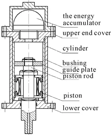
Figure 1.Magnetorheological damper structure

Figure 2.The principle diagram of themagnetorheological damper of aircraft landing gear
When the damper is working,the piston rod pushes the magnetorheological fluid in the oil cavity flow into the air chamber during the compression stroke,then the energy is absorbed by the compressed gas.The damping force is produced when the magnetorheological fluid passes the annular gap under the action of pressure difference,which can dissipate the vibration impact energy.When the piston rod moves to a certain degree,the pressure of the air chamber becomes big enough,which could make its inverse kinematics,then the extend stroke begins.At this stage,the high pressure of compressed gas makes the magnetorheological fluid reversely flow through annular clearance,then the damping force is produced and further consumes the energy.When there is no magnetic field,the MRF in the cylinder is similar to Newton fluid and its movement characteristics is the same with the general oil,when magnetic field is used,the MRF has the characteristics of non-newton fluid,then the magnetic field in the damping channel could be adjusted by controlling the size of the current,and the dynamic viscosity and yield strength of the magnetorheological fluid in the damping channel could also be changed.Therefore,the damping force needed in different time could be controlled and it could achieve good damping effect through real-time control.
3.The structure design
3.1.The magnetic circuit design
The magnetic circuit design is important for the structure design of magnetorheological damper of landing gear.The finite element software ANSYS is used to calculate and simulate the magnetic field of the damper.According to the magnetic circuit diagram of the magnetorheological damper in Figure 3,the 3D axisymmetric finite element model could be obtained,as shown in Figure 4.

Figure 3.The magnetic circuit diagram of the magnetorheological damper

Figure 4.3D axisymmetric finite element model of magnetic circuit
As the magnetic circuit structure shown in Figure 3,the calculation formula for the damping force in the gap could be expressed as follows[15]:

Where,ηis the viscosity of the magnetorheological fluid,L is the length of the piston,Apis the effective area of piston under pressure,D is the diameter of the piston,h is the thickness of the gap,U(t)is the relative motion of the piston and cylinder,τyis the yield stress of MRF.
In the equation(1),the damping force is composed by two parts,i.e.,the former was the viscous damping force and the latter which was related to the yield stress of magnetorheological fluid was the coulomb force and it is the adjustable damping force. This yield stress is closely relative to magnetic induction intensity B.In order to increase the controllable damping force of magnetorheological damper and improve the static characteristic,the magnetic induction intensity in the gap should be increased.
However,according to gauss’s law,there was:

Where,Bfis the magnetic induction intensity of the clearance,Sfis the magnetic flux area of the circular working area,Beand Seare the magnetic induction intensity and magnetic flux area of other areas,respectively.
The equation(2)shows that the magnetic field intensity of other parts of the magnetic circuit could be increased when the magnetic field intensity of the working gap gets increased in certain cases.According to the magnetic properties of magnetic materials,they have certain magnetic saturation,when the magnetic induction intensity exceeds their magnetic saturation,the magnetic induction intensity of the whole magnetic circuit would not increase with the increment of the current,the magnetic induction intensity of the working gap also would not get increased correspondingly.
Since the ANSYS parametric design language APDL could give an optimization,which takes the maximum magnetic induction intensity the clearance as the optimization goal and the maximum magnetic induction intensity of the magnetic circuit is the constrained condition,and the diameter of the piston rod,the height of the magnetic disk,the thickness of the cylinder and other parameters are the design variables to optimize the magnetic circuit.Therefore,the optimal structure and parameters would be obtained. The Figure 5 is the optimization iterative curve and Figure 6 is the magnetic induction intensity distribution nephogram after the optimization.From the graphs we could see that the magnetic induction intensity in the gap could reach to the maximum value after 11 iterations,the magnetic induction intensity distribution of the magnetic circuit will become more reasonable.The largest magnetic induction intensity is 1.109 T,which has not met the electrical pure iron DT4 magnetic saturation.
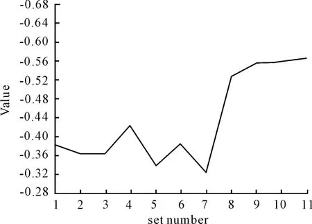
Figure 5.Curve of magnetic circuit optimization iteration
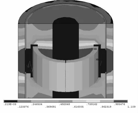
Figure 6.The magnetic induction intensity distribution nephogram of the optimized magnetic circuit
3.2.The general design
Since the magnetorheological damper controls the damping force only through the controlled current,the magnetic induction intensity in the gap would not increase infinitely due to magnetic saturation.Therefore,the damping force would not be increased with the increase of the current and the magnetorheological damper of the lading gear could not achieve good effect only by controlling the electric current to adjust the damping force when the impact load is big enough and the structure is limited.By retrieving,there had not yet found effective technical methods to solve the above-mentioned problems. Based on this question,this paper designed a magnetorheological damper which has coil inside with oil needle,and it could achieve current control and schedule control at the same time.Therefore,it could improve the efficiency of vibration and adjust the scope of the damping force,at the same time,its safety coefficient also could be improved,the structure diagram is shown in Figure 7.
When the damper is working,the guide plate is pressed to the gas chamber with the movement of the piston rod,the magnetorheological fluid at the top of guide plate flows through the fuel-efficient hole in the top of the piston rod,and flows through the piston rod which is hollow in the top part,then flows through the annular space after the radial hole in the piston. There are several radial annular rectangular grooves in the piston of the damper,the magnetorheological fluid would slow down when it flows through the rectangular tank,the fluid will be expanded,under the action of electromagnetic field,and due to the effect of dissipation of the rectangular spiral groove,the kinetic energy which is converted into heat energy will be cut.Therefore,the magnetorheological damper,whose damping channel is rectangular cross section,would produce more damping force;Besides,it adopts the variable cross-section oil needle which could change the damping force according to the change of the stroke,and when the semi-active control system of the magnetorheological damper expired,it could degenerate into an efficient passive control damper,so this could make the damping system of the landing gear more safe.
4.Analysis and establishment of the simulation model
4.1.Analysis and establishment of the vibration test model
According to the working principle and structure of the above-mentioned magnetorheological damper,when the damper is working,the main damping force are the viscous force,coulomb force in the piston,and viscous force in the oil needle,air chamber force and friction force.
1)The viscous force and coulomb force in the piston
Because the design of the magnetorheological damper adopts the differential pressure and shear mix work mode,the viscous force and coulomb force in the piston could be evaluated as follows:

Where,Apis the effective area under pressure of piston,u(t)is the relative velocity of the piston and the cylinder,D is the diameter of the piston,L is the effective length of the piston,h is the working gap,ηis the dynamic viscosity of the fluid,τyis the yield stress.
2)The viscous force in the oil needle
The viscous force in the oil needle is produced by the pressure difference when the magnetorheological fluid flows through the holes,thus through the formula derived,the viscous force in the oil needle could be evaluated as follows:
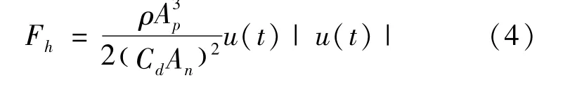
Where,ρis the density of MRF,Cdis the shrinkage flow coefficient of the oil hole whose average value is 0.9,Anis the flow area of the magnetorheological fluid at the orifice.
3)The force of air chamber
The changing volume of the damper in the process of work will be compensated by internal airchamber,so the force of the air chamber could be expressed as follows:
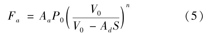
Where,Aais the area of compressed air,Adis the cross-sectional area of the piston rod,S is the stroke of the piston,P0is the initial air pressure,V0is the initial volume of the gas,n is the polytropic index of the gas.
4)The friction
The friction mainly includes the friction between the o-ring and cylinder wall,which is in the guide plate,and the friction between the piston rod and the o-ring in the lower cover,its value is usually a fixed constant,and it could be expressed as:

So the total damping force is:

Then,the damping force model identified in equation(7)could be established by using Matlab/Simulink software,as shown in Figure 8:

Figure 8.Vibration test simulation diagram
4.2.Analysis and establish drop test model
The mechanical structure of the plane is very complicated,it is usually difficult to establish precise landing buffer model,but for the theoretical study,we could simplify the model and select a single landing gear to establish dynamic model of the lading gear as shown in Figure 9.The top of the damper is connected to the fuselage,the fuselage and the quality of the load on the fuselage is called the sprung mass M1,this part is rigid quality;the upper of the absorber is connected to the strut,and the strut connects to the tire,the quality of the strut and the tire are called sprung mass M2.The tire is flexible,which could be equivalent to a spring.

Figure 9.Dynamic model of single landing gear
According to the Figure 9,we could establish the dynamic model of landing gear according to the Newton’s second law,and the motion differential equation could be established.For the M1,there exists the following equation:

For the M2,the corresponding equation is as follows:

Where,M1is the sprung mass,M2is the nonsprung mass,X1is the displacement of the fuselage,X2is the tire displacement,k1is the spring stiffness of the air in the damper,k2is the stiffness of tire,C is the viscous damping coefficient,f is the coulomb force,which is related to the yield stress of magnetorheological fluid.
All variables mentioned above have the following relationships:

The simulation model of the drop test of the damper is established by the software of Matlab/Simulink,as shown in Figure 10.
5.Damping characteristic test
The damping characteristics of damper include indicator characteristics and speed characteristics,they are the key indicators to show the performance of magnetorheological damper.In order to study the characteristics of the magnetorheological damper designed,the damping characteristic test are carriedout,the equipment is shown in Figure 11.The top of the damper is fixed by triangle chuck and fixed positioning fixture,the bottom of the damper is connected to force sensor,and through the fixture,the force sensor is connected with the triangle chuck,which is located at the bottom of the vibration platform.During test process,the top of the damper is fixed,the sine excitation is applied to the bottom of the damper,then we could study the damping force characteristics of the damper in different current situations by changing the frequency and amplitude of the sine excitation.

Figure 10.The drop test simulation diagram

Figure 11.Magnetorheological fluid shock absorber damping characteristics test
During the test,the amplitudes of the excitation applied are 1 mm,2 mm,…,7 mm,the frequencies are 1 Hz,2 Hz,…,8 Hz,and the current imposed are 0 A,0.1 A,…,0.5 A.There only listed the indicator diagram and the damping force and velocity diagram of the damper when the current are 0 A,0.1 A,0.3 A,0.5 A.The amplitude is 5 mm,the frequency is 4 Hz.The Figure 12 is the indicator diagram of the damper when the excitation amplitude is 5 mm and the frequency is 4 Hz.The Figure 13 shows the relationship between the damping force and velocity.

Figure 12.The shock absorber of the indicator diagram when the amplitude is 5 mm and the frequency is 4 Hz

Figure 13.The damping force-velocity diagram of the shock absorber when the amplitude is 5 mm and the frequency is 4 Hz
The Figure 12 shows that,the damping force of the damper is gradually increased with the increase of the current,and the area of the curve surrounded also increases with the increase of the current,it shows that the energy consumption of the damper is gradually increased with the increase of the current.When the current is0.1 A,the change of the damping force is not obvious,that is because the magnetic induction intensity in the annular clearance is small when the current in the coil is small,and it is not in the scope of 0.3~0.5 T which is the normal work of the MRF,but when the current gets increased to 0.3 A,the magnetic induction intensity in the gap also gets increased to the work scope of MRF,the damping force could have great change,it also could be seen from the diagram that the indicator diagram is not orderly rectangular,and the damping force has certain upward migration,this is because the damping force of the shock absorber includes the elastic force of the air chamber,whose value would increase with the increase of displacement.It could be seen from the Figure 13 that when the current is constant,the damping force also gradually gets increased with the increase of velocity of the piston of the shock absorb-er,but the increasing extent is not large,this is because the viscous force takes little proportion in the total damping force at low speed.The speed characteristic graph also shows that the MRF basically conformed to the constitutive relation described in the Bingham model,but the change curve of the damping force of the damper is not coincidence with the change of the velocity of the piston,this is because the damping force of the shock absorber exists hysteresis phenomenon.The indicator diagram and the speed characteristic figure show that the damping characteristics of shock absorber is good,it has large changeable range of damping force,and good energy consumption performance,and good controllability,it is suitable for application in damping structure of the semi-active control.
The Figure 14 is the comparison of the test data and the simulation results when the current is 0 A,and the amplitude is 5 mm,and the frequency is 4 Hz.The Figure 12 is the results of simulation when the current is0 A,and the amplitude is 60 mm,and the frequency is 4 Hz.

Figure 14.The results compare of simulation and test data when the current is 0 A and the amplitude is 5 mm and the frequency is 4 Hz
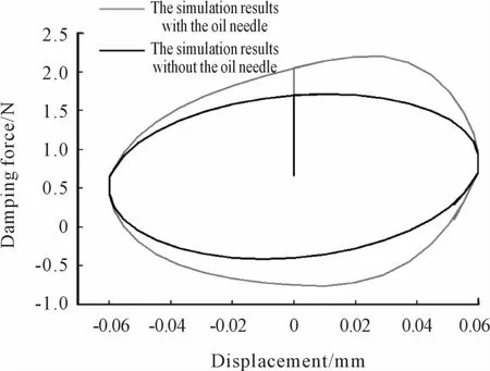
Figure 15.The results compare of simulation and test data when the current is 0 A and the amplitude is 60 mm and the frequency is 4 Hz
The Figure 14 shows that the simulation results agreed well with the test data.There only could take vibration test in small amplitude due to the limitation of equipment,and the oil needle plays a small role in this case.As shown in Figure 14,the result of simulation of shock absorber with oil needle is almost the same with the result of simulation of the shock absorber without oil needle,but there still could be seen that the energy consumption of the former is slightly greater than the latter.In Figure 15,it could obviously see that the energy consumption of the shock absorber has large increase after increasing the oil needle structure due to the increasing of amplitude.
6.Drop test
In order to further study the shock absorption performance of the shock absorber in landing gear,the drop test is conducted.The drop test of landing gear is a kind of dynamic test to simulate the impact of the aircraft lading.In this test,it determines the condition of landing gear by measuring parameters of the landing gear,and test the strength,stroke,and energy efficiency performance of the shock absorber of landing gear to decide whether it could meet the design requirements.
The drop test equipments are shown in Figure 16,the hanging basket could move up and down on the slippery course,and the magnetorheological damper are connected with the hanging basket and tired through fixtures,there exist displacement sensors on the hanging basket and the wheel axles to measure the displacement of the shock absorber and hanging basket.There also exists an acceleration sensor on the hanging basket,there are vertical load sensors on bottom of the drop-test platform to measure the vertical load of the shock absorber when it is dropping down.During test process,the hanging basket is raised to the set height,the hanging basket and the shock absorber will be droped down through manipulating the lock hook which is in pneumatic control,then the displacement sensor,load sensor and acceleration sensor will record the corresponding data,respectively.It could get the data in different heights and currents by controlling the release height and the size of the current.
The load in this drop test is 300 kg,and the drop test height in the experiment are 20 mm,40mm,60 mm,80 mm,100 mm,and the current are 0 A,0.1 A,0.2 A,0.3 A,0.4 A,0.3 A.

Figure 16.Shock absorber drop test object chart
Figure 17 is the changing curve of largest vertical load of the magnetorheological damper in different drop heights and different currents.In this picture,in the same drop height the largest vertical load of the shock absorber get all increased when the increase of current,that is because the magnetorheological fluid in the annular space is magnetized,and it is changed from the free fluid state into a kind of solid state,thus the buffer resistance of shock absorber has been increased.

Figure 17.The relation of shock absorber maximum vertical load and electric current
The Figure 18 is the maximal displacement curve of the piston of the magnetorheological damper in different heights and different currents.It could be seen from this diagram that the maximum displacement of the piston of the damper is gradually decreased with the increase of current in the same drop height,that is because the damping force of the shock absorber gets increased with the increase of current,so that the shock absorber could consume the energy of vibration and impact in small displacement.

Figure 18.The relationship of piston’s displacement and current
Figure 19 is the curve of total vertical load of the damper in different current when the drop height is 100 mm.It could be seen that with the increase of current,the vertical load of shock absorber also gets increased.When the current is different,the damping force has the same change trend,so the damping force of the damper is changing at each time with the change of the current,which would change the damping force of the damper in different time,so as to improve the damping effect.

Figure 19.The shock absorber damping force change curves at different current when the drop height is 100 mm
The Figure 20 is the work and energy chart in different currents when the drop height is100 mm.It could be seen that with the increase of current,the damping force of the damper is also increased,which would reduce the trip of the damper,and also it is confirmed that the relationship between the displacement of the piston and the current is shown in the Figure 18,the increase of the current would result in the increase of damping force,so that the shock absorber could consume the drop impact energy when the displacement is small,the larger of the current,the greater increase of the damping force,and the displacement of the shock absorber is smaller.

Figure 20.The work flow diagram at different current when the drop height is 100 mm
The Figure 21 and Figure 22 are the comparison of simulation results and the test data when the current is 0 A and 0.5 A,respectively.The drop height is 100 mm,it could be seen from the figure that the simulation results are basically consistent with the experimental results.Structure of oil needle has more energy consumption than structure with out oil needle. With the increase of current,the vertical load gets increased 16.6%,and the stroke is reduced 31.2%.
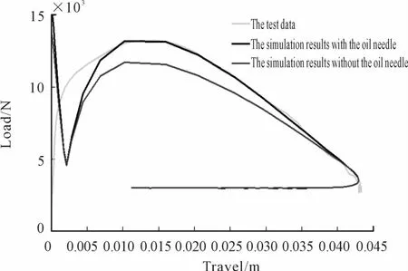
Figure 21.The results compare of simulation and test data when the current is 0A and the drop height is 100 mm

Figure 22.The results compare of simulation and test data when the current is 0.5 A and the drop height is 100 mm
7.Conclusion
Based on the magnetorheological damper of landing gear previous studied,a new type of structure of the magnetorheological damper is proposed and studied the damping characteristic test and drop test,the following conclusion could be drawn.
1)The shock absorber has good damping characteristics,large range of adjustable damping force,the energy consumption is good,and good controllability,so it is suitable to the damping structure of semi-active control.
2)The damping force of damper would increase and the vibration amplitude would reduce when the current is changed in different drop heights,thus it could improve the shock absorption effect of the shock absorber.
3)The adoption of the structure of the oil needle not only makes the energy consumption of the damper large in the buffer process,damping performance is better,but also makes the damper could change the damping force when the current fails,which could increase the safety of the shock absorber.
4)The application of the magnetorheological damping technology in the shock absorber of aircraft landing gear is the exploration to the application of the magnetorheological technology,which has great practical engineering value to improve the shock absorption efficiency of aircraft landing gear.
Through the studied of the test,we can find that the increase size of the current is very important in the process of the adjustment of the damping force of shock absorber,which also affects the shock absorption effect in different drop heights.As to the shock absorber of aircraft landing gear,the damping force is different in the process of takeoff and landing,which needs to be adjusted according to actual condition,so there needs related control algorithm to control the size of current applied,which is the focus of the next step research.
[1] Liu Hui,Gu Hongbin,Chen Dawei.Application of High-speed Solenoid Valve to the Semi-active Control of Landing Gear[J],Chinese Journal of Aeronautics,2008,21:232-240.
[2] Aircraft design manual editorial committee.Aircraft de-sign manual,14th books:take-off landing system design[M].Beijing:Aviation Industry Press,2002.12.
[3] Zhu Shuhua,Tong Mingbo,Xu Jie.Design of sign of new passive adaptive shock absorber of landing gear and study of its landing performance[J].Transactions of Nanjing University of Aeronautics&Astronautics,2009(26):112-124.
[4] JIA Yuhong,WU Xiaojuan.Application of Magnetorheological Damper to Landing Gear[J],AIRCRAFT DESIGN,2007,27:123-126.
[5] He jie,Gao lixia,Long zheng,et al.Theoretic and experimental study of chain-formation mechanism for MRF[J].Jounal of functional materials,2013,44:251 -160.
[6] Zhou yun,Tan ping,Magnetorheological damping control theory and technology[M],Beijing:Science press,Mar,2007.(in Chinese)
[7] Choi Y T,Wereley N M.Vibration Control of a Landing Gear System Featuring Electrorheological/Magnetorheological Fluids[J].Journal of Aircraft,2003,40(3):432-439.
[8] Batterbee D C,Sims N D,Stanway R.Magnetorheological Landing Gear:1.A Design Methodology[J].Smart Mate rials and Structures,2007,16(6):2429-2440.
[9] Batterbee D C,Sims N D,Stanway R.Magnetorheological Landing Gear:2.Validation Using Experimental Data[J].Smart Materials and Structures,2007,16(6):2441-2452.
[10]Jia Yuhong,Wu Yongkang,Zhang Guanchao.An Experimental Systemfor Semi-Active Control of Landing Gear[J].Research and exploration in laboratory,2006,25(2):451-467.
[11]Jia Yuhong,Wu Xiaojuan.Fuzzy control of landing gear based on M R damper[J].Journal of Beijing University of Aeronautics and Astronautics,2007,33(11):1264-1267.
[12]LIU Hui,GU Hongbin,WU Dongsu.Shock absorber performance study of semi-active control of landing gear[J].Acta aeronautica et astronautica sinica,2006,27(5):110-119.
[13]Wang Wei,Xia Pinqi.Adaptive Control of Helicopter Ground Resonance with Magnetorheological Damper[J]. Chinese Journal of Aeronautics,2007,20:501-510.
[14]TIAN Jing,DING Li,KONG Ling-shuai,et al.Simulation and Analysis of Semi-Active Control for MR Damper Landing Gear[J].Chinese Hydraulics&Pneumatics,2012(1):156-162.
[15]Bai Yu.Study of landing gear damper optimal control on the principle ofMR[D].Tianjin:Civil Aviation University of China,2009.
飞机起落架磁流变减震器的设计与试验研究*
祝世兴†,卢铭涛,杨永刚,田 静,陈 帮
中国民航大学航空工程学院,天津 300300
提出了一种带油针的磁流变减震器的结构与工作原理,并进行了结构设计和磁路优化设计,最后通过阻尼特性试验和落震试验研究了该减震器的阻尼特性和减震效果。结果表明:该减震器的阻尼特性良好,阻尼力调节范围大,耗能性能好。通过改变电流,可以改变不同落震高度时的减震器最大垂直载荷和活塞位移,改善了传统起落架减震器的减震效果,对起落架磁流变减震器的研究和应用具有指导意义。
磁流变减震器;磁路;油针;阻尼特性;落震试验
V226+.2
10.3969/j.issn.1001-3881.2014.18.007
2014-06-02
*Project supported by the NSFC“Natural Science Foundation of China”(61172013)
†Shi-xing ZHU,Professor.E-mail:8337899_tj@sina.com
Figure 7.The structure diagram of magnetorheological damper with oil needle
猜你喜欢
杂志排行

机床与液压的其它文章
- Electro-mechanical power coup ling system for PHEV with high price-performance ratio*
- Research on multi-axial multi-excitations road simulation test method for AMT actuator*
- Research on the inference of CNC machine fault based on Bayes and FTA
- Design and application of attitude measuring device for DC power output filter circuit
- Design of 20 t forging manipulator clam p rotation hydraulic control system*
- Particle removal by an oscillating bubble in the pipe*