Particle removal by an oscillating bubble in the pipe*
2014-06-09MingXUGuoliangHUJunZOUChenJI
Ming XU,Guo-liang HU,Jun ZOU,Chen JI
1School of Mechatronics Engineering,East China Jiaotong University,Nanchang 330013,China;2The State Key Laboratory of Fluid Power and Mechatronic Systems,Zhejiang University,Hangzhou 310027,China
Particle removal by an oscillating bubble in the pipe*
Ming XU†1,Guo-liang HU1,Jun ZOU2,Chen JI2
1School of Mechatronics Engineering,East China Jiaotong University,Nanchang 330013,China;2The State Key Laboratory of Fluid Power and Mechatronic Systems,Zhejiang University,Hangzhou 310027,China
In the paper,particle was removed in the pipe by an oscillating bubble.The bubble was generated using a very low voltage of 55 V.The dynamic behavior of the particle and the shape change of the oscillating bubble were recorded using a high-speed video camera,and the images were captured at a speed of 15000 f/s(frames per second).The experimental results show that the velocity of the particle is dependent on the bubble initial position and the bubble length along the pipe.
Oscillating bubble,Particle removal,Rigid pipe
1.Introduction
It is known that the surface cleaning is achieved by the oscillating bubble jetting behavior.When oscillating bubbles expand and collapse close to the boundary,a shear flow is generated which is able to remove particles from the surface.Particles on the substrate are removed by the shock wave and jetting induced by the bubble collapse[1].Liquid jetting plays an important role in the particle removal process.Ohl et al proved that the particles were removed by shear flow induced by the collapse of the bubble in their experimental results[2].However,it rarely mentioned particle removal in the pipe by the bubble collapse.It is necessary to further study the particle removal in the pipe with the bubble applied in the confined environment in the industry and biomedical areas[3-6].
When a single cavitation bubble collapses,it may generate micro jets and pressure wave that transfer with considerable instantaneous imploding energy. Directional jetting from the oscillating bubble in the pipe is uesd to remove blockage in the pipe.This can perhaps be exploited for the removal of blood clots in the vessels or clog in the microfluidics system.The object of the present work is to investigate the dynamic behavior of the particle in the pipe and the influence factors on the partilce removal veolcity.At the same time,the shape change of the bubble is recorded by a high speed viedo camera.
2.Experimental setup
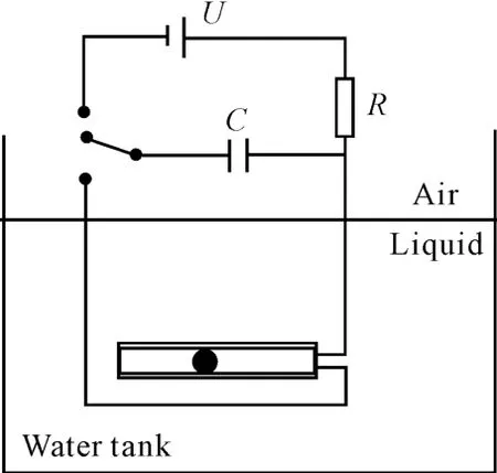
A schematic diagram depicting the experiment arrangement for investigating the particle removal in the pipe by an oscillating cavitaion bubble is shown in Figure 1.The cavitation bubble is generated by a simple low voltage electric spark discharge circuit[7].The experimental system that we used consult their circuit design.The circuitry consists of a 55 V DC supply,5 300μF capacitors(two of 1 000μF and one of 3 300μF),and a 1 kΩresistor.The electrodes are connected to the main circuit through insulated wires.The capacitors are discharged by short-circuiting them through the crossed electrodes. The copper-alloy electrode(0.26mm in diameter)is used to generate a single oscillating bubble in thepipe.The size of the bubble reaches-5 mm in the diameter and thus the influence of electrodes on the bubble behavior can be ignored.The remnants of the burnt electrodes may bother experiment observation but will not affect bubble dynamic parameter measurement.The remnats of the burnt electrodes serve as black particles which aids visualization jetting derction.
The experiments are conducted in a glass pipe with a inner diameter Dt=6 mm,the pipe length Lt=87 mm and the particle diameter Dp=5.9 mm which is shown in Figure 2.The particle is on the left side of the bubble in the experiment,so the leftward direction is taken as positive.
The tank is an open-top transparent tank with the dimensions of 21 cm×21 cm×21 cm.The tank filled up to approximately 80%with liquid.The liquid is using deionized water.In order to observe the bubble and particle behavior,a high speed video camera(FASTCAM-ultima APX,USA)fitted with a Nikkor 60 mm micro lens was used,the flickerless backlighting produced by a high-intensity LED lamp with a thin sheet of drafting paper as a diffuser.The images are captured at a speed of15 000 fps(frames per second).The experiments were carried out under the room temperature(20°C)and atmospheric conditions.

Figure 1.Schematic representation of the experimental setup

Figure 2.Definition of the pipe length Lt,the pipe inner diameter Dtand the particle diameter Dp
3.Results
A lot of experiments were done and some typical experimental results are shown in the paper.The displacement of the particle and the position change of the oscillating bubble are analyzed and the influence factor of the particle removal velocity is discussed.
3.1.Particle rem oval process
It is necessary to quantify the relative location between the oscillating bubble and the particle in the study.The affect(effect)of the particle on the liquid column quality should be considered.Now it is assumed that the movement speed of the particle is equivalent with the whole axial speed of the liquid column in the pipe.So the steel particle in the experiment is equivalent to a liquid column with length Lp≈16 mm.(Lt+Lp)is seen(defined)as the whole length of the liquid column and then the relative locationof the bubble excitation and the x*pof the particle is given where the value changes between zero and one.In the experiment the pipe inner diameter is relatively small and the bubble occupies the whole channel in the radial direction.The maximum axial length Lbmaxis used as the property parameter of the bubble intensity and the dimensionless form is defined as
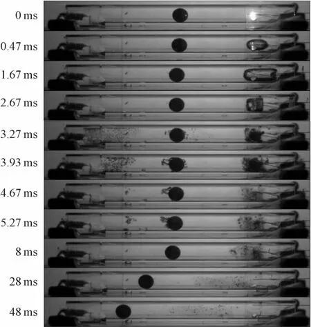
Figure 3 is the particle removal process in the rigid pipe.The initial parameters areThe annular cavitation occurs in the edge of the pipe which is caused by the shock wave induced by the bubble generating.The cavitation ring moves toward the pipe outside which can be seen clearly in the 1.67 ms image in the Figure 3. The development process of the bubble is not asymmetrical and expansion velocity of the right side is faster.The particle moves to the left side under the pressure coming from the bubble expansion.The right side of the bubble first begins to collapse retraction and at the same time particlemoves to the right side slightly which is shown in the 1.67 ms image. At the end of the bubble collapse(3.27 ms)the shock wave emerges and obvious secondary cavitation phenomenon is observed which distributes around the particle and left side of the pipe.A great deal of small bubbles formed by the bubble collapse rebound and collapse again between the 3.27ms and 5.27ms and the secondary cavitation phenomenon disappear from left to right.Through the motion of the small bubbles consist of the residual gas after 8 ms,it can be judged that the whole velocity toward left of the liquid column in the pipe is achieved after the bubblecollapse.The particle pushed by the surrounding liquid moves toward left and the velocity keeps about 0.47 m/s.

Figure 3.Particle removal process by an oscillating bubble in the pipe.(5)
The motion trajectory of the particle and the bubble along the axis of symmetry at both ends can be obtained by the image analysis shown in the Figure 4.It can be found that the expansion range of the bubble right wall is larger.The expansion rang reaches the 9 mm and the bubble right wall shrinks earlier than the left wall.About 1.5 mm drift is measured compared the contact points of bubble left and right wall with the initial excitation position.After the bubble collapse,the particle appears small vibration in the process of the bubble rebound and the secondary collapse.The particle velocity is gradually stabilizing after 7 ms.

Figure 4.Particle displacement and bubble shape change()
The case of the particle and the bubble locates on the same side of the pipe and the particle locates outside are shown in the Figure 5.The initial parameters arerespectively.From the Figure 5,the particle moves toward left when the oscillating bubble begins to expand and reaches the extreme position at 3.03 ms. Then the oscillating bubble begins to shrink and collapses from the left side producing a jetting toward the right side in this process.The particle is pushed toward right and a low pressure region is formed at the left side of the bubble and the secondary cavitation occurs shown in the 4.93 ms image.The bubble begins to collapse to a minimum volume and rebounds at5.73 ms.The liquid column in the pipe acquires a velocity toward right according to the shape of the rebound bubble at7.27 ms.The image at30 ms shows that the bubble has stabilized and the particle pushed by the liquid in the pipe moves toward right at a speed about0.136 m/s.

Figure 5.Particle removal process by an oscillating bubble in the pipe.()
Figure 6 gives the motion trajectory of the particle and the bubble along the axis of symmetry at both ends.The bubble dynamic behavior is similar to the case of the Figure 4 but the direction is opposite.The end position of bubble collapse has 1.5 mm drift toward right compared with the initial excitation position.In this case,the particle vibration is more obvious after the bubble collapse and a stable speed toward right is obtained at15 ms.

Figure 6.Particle displacement and bubble shape change9)
3.2.Influencing factors of the particle removal velocity
The particle may moves toward or far away from the bubble excitation position affected by the bubble collapse if we compare the removal process in the Figure 3 and the Figure 5.The movement direction of the particle is relevant with the jetting induced by the bubble collapse.Through analyzing directional jetting induced by the eccentric bubble in the pipe,it can be deduced that the bubble relative position in the pipe is the important factor that influence the particle movement direction.
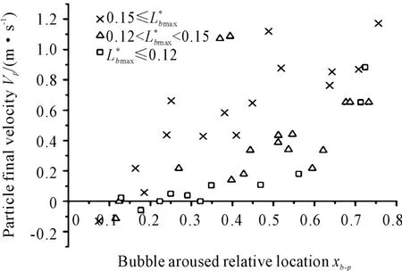
The relationship between the particle final velocity vpand the relative position of the bubble excitation is given in the Figure 7 and Figure 8.The particle has obtained a stable velocity before leaving the pipe. The regioncannot obtain valid data because the particle is too close to the end of the pipe and the particle will break away from the pipe when the bubble begin to collapse.Theis the case that the bubble and the particle locate the left side of the pipe simultaneously,the value of the velocity vpwill go negative and the particle final velocity faces the bubble,as shown in the Figure 7.The vicinity of theis the critical position where the particle velocity direction will change.The particle final velocity will be close to zero and keep immobile at the end of the bubble collapse.When theis beyond the critical value,the direction of the particle final velocity will be away from the bubble.With the excitation position of the bubble moving toward the right,the value of the velocity vpincreases obviously.By analyzing those results,it can be concluded that the direction of the particle final velocity is determined by the initial excitation position of the bubble.The value of the particle final velocity is also influenced by the initial exciation position of the bubble.

Figure 7.The relation between the particle final velocity and bubble excitation location-the particle is equivalent to the liquid column
In the Figure 8,the value 0 and 1 of theis the particle initial position and far end of the pipe respectively.The influence of the distance between the particle and the bubble is introduced on the abscissabasis shown in the Figure 7.The distribution of the velocity vpin the Figure 8 is more diffuse compared with the Figure 7 and the trend of the positive correlation will be significantly weakened.The sign of the vpis uncertain when the value of theis minimal and the critical value of thecannot be given.The evidence shows that the influence of the distance between the particle and the bubble on the final velocity of the particle is not obvious.
In the Figure 7 and Figure 8 the data points are divided into three categories according to the size of the bubble.The dimensionless value of the bubble longest axis dimension is considered as the characteristic parameter.It can be found from the Figure 7 that the larger size bubble brings the higher final velocity of the particle as the value of theis close.

Figure 8.The relation between the particle final velocity and bubble excitation location-the particle is equivalent to zero coordinate
The particle trajectory is shown in the Figure 9 where the bubble position of the three groups is closebut the size of the bubble is obviously different.So the finial velocity of the particle increases greatly with the bubble size increasing. At the same time the particle vibration will also get more violently.It is reflected that the more time is acquired before the particle velocity reaches a stable value.The experimental result shows that there has been twice obvious“recovery”processes at Lbmax= 18.9 mm.
The analysis of the experimental data shows that the final direction and value of the particle velocity is affected by the bubble excitation positionand the maximum axial lengthof the bubble.

Figure 9.The effect of the bubble maximum length on the particle remova
4.Conclusion
The application of the particle removal by the eccentric bubble in the pipe is studied by the experiment method.The particle can obtain a stable velocity after the vibration.The bubble excitation positionis the critical value that the final velocity direction of the particle will change at the point.The particle will acquire a velocity far away the pipe when the particle is located in the end of the pipe.The velocity of the particle becomes larger when increasing eccentric degree and the bubble size.
[1] SongW D,Hong M H,Lukyanchuk B,et al.Laser-induced cavitation bubbles for cleaning of solid surfaces[J].Appl.Phys.Lett.2004,95-2592.
[2] Ohl CD,Arora M,Dijkink R,et al.Surface cleaning from laser-induced cavitation bubbles[J].Appl.Phys. Lett.2006,89:074102.
[3] Yoshizawa S,Ikeda T,Ito A,et al.High intensity focused ultrasound lithotripsy with caviitating microbubbles[J].Med Biol Eng Comput,2009,47:851-860.
[4] Mastin B J,Sherrard R M,Rodgers JH,et al.Hybrid cavitation and constructed wetland reactors for treatment of chlorinated and non-chlorinated organics[J].Chem. Eng.Technol,2001,24:97.
[5] Sangave PC,Gogate PR,Pandit A B.Ultrasound pretreatment for enhanced biodegradability of the distillery wastewater.Ultrason[J].Sonochem,2004,11:197.
[6] Crum L A.Cavitation microjets as a contributory mechanism for renal calculi disintegration in ESWL[J].J Urol.1988,140:1587-1590.
[7] Turangan CK,Ong G P,E.Klaseboer BC.Khoo.Experimental and numerical study of transient bubble-elastic membrane interaction[J].J.Appl.Phys,2006,100:054910.
空泡应用于管道内粒子移除的研究*
徐 明†1,胡国良1,邹 俊2,吉 晨2
1.华东交通大学机电工程学院,南昌 330013
2.浙江大学流体动力与机电系统国家重点实验室,杭州 310027
研究了刚性管道中粒子在振动空泡的作用下移除的过程,振动空泡由一个55 V的低压电路产生。高速相机记录了空泡作用下粒子的动力学行为及空泡的形状变化过程,高速相机的帧率设为15 000 f/s。结果表明:粒子的移除速度受空泡产生的初始位置和空泡在管道中的轴向长度的影响。
振动空泡;粒子移除;刚性管道
TH137.5
10.3969/j.issn.1001-3881.2014.18.003
2014-04-30
*Project supported by the National Nature Science Foundation of China(51165005),and the International Cooperation Project of Jiangxi Province of China(20132BDH80001)
†Ming XU,PhD.E-mail:xuming123@zju.edu.cn
猜你喜欢
杂志排行
机床与液压的其它文章
- Electro-mechanical power coup ling system for PHEV with high price-performance ratio*
- Design of 20 t forging manipulator clam p rotation hydraulic control system*
- Research on the inference of CNC machine fault based on Bayes and FTA
- Design and application of attitude measuring device for DC power output filter circuit
- Simulation of automobile ESP system based on fuzzy control*
- Research on multi-axial multi-excitations road simulation test method for AMT actuator*
