3D Numerical Study on Compound Heat Transfer Enhancement of Converging-diverging Tubes Equipped with Twin Twisted Tapes*
2012-02-14HONGYuxiang洪宇翔DENGXianhe邓先和andZHANGLianshan张连山
HONG Yuxiang (洪宇翔)**, DENG Xianhe (邓先和) and ZHANG Lianshan (张连山)
Key Lab of Enhanced Heat Transfer and Energy Conservation of Ministry of Education, School of Chemistry and Chemical Engineering, South China University of Technology, Guangzhou 510640, China
1 INTRODUCTION
Heat transfer enhancement technology plays an important role in chemical industry, power engineering, air conditioning and many other industries, especially in the applications of energy saving and waste heat recovery. In general, according to whether external power is needed, the techniques for heat transfer enhancement can be divided into two categories [1].One is the active strengthening technology, which needs extra external power sources, for example, electrostatic fields, surface vibration and jet impingement,etc. The other is the passive strengthening technology,which needs no direct use of external power. Due to its less energy consumption, easier operation and higher reliability, the passive strengthening technologies, such as wall roughness (converging-diverging tube, grooved tube and corrugated tube, etc.), additives, surface coatings and swirl flow inducement(twisted tape, snail entrance and helical screw tape,etc.), are used more widely.
Compared to a plain tube, converging-diverging tube (CD) imparts turbulence to the near wall flow which thins the boundary layer and enhances heat transfer. The geometry of a CD sketched in Fig. 1 is characterized by the pitch length (P), converging to diverging pitch ratio (δ=P1/P2) and rib height (e). Li[2] reported experimental data for two bare convergingdiverging tubes with δ=8.4︰5 and 5︰8.4 at e=0.8 mm and P=13.4 mm. He found that both Nu and f for CD with δ=8.4︰5 were higher than that for δ=5︰8.4, and the case with δ=8.4︰5 performed better overall thermal performance than that with δ=5︰8.4.Chen et al. [3] further analyzed the heat transfer enhancement mechanism of the CD by a 2D numerical simulation. Their results show that the synergy between the temperature gradient and velocity vector near the wall is one of the main parameters to control heat transfer in fully developed turbulent flow. Insertion of twisted tape is one of the effective measures to enhance heat transfer rate by creating swirling flows,mixing fluid between the mainstream zone and the near wall zone. Because of its low cost and easy manufacture, the twisted tape has been widely employed to produce compact heat exchangers and to upgrade the old heat exchangers over the past few years. Manglik and Bergles [4, 5] concluded that the tube partitioning and flow blockage, longer flow path and tape induced secondary fluid circulation were mainly the reasons for heat transfer enhancement by using the twisted tape in the plain tube. Saha et al. [6, 7]have experimentally investigated the heat transfer and friction factor characteristics of water in a plain tube equipped with regularly spaced twisted tapes in laminar and turbulent flow. It was found that the regularly spaced twisted tapes performed better than the full-length twisted tapes in laminar flow, while the variation tended to be opposite in turbulent flow. Abu-Khader [8]conducted an industrial study to investigate the effect of twist ratio and tube diameter on heat transfer coefficient and friction factor of a tube fitted with twisted tapes. It was found that the twisted tapes performed better in laminar flow than in turbulent flow, and the twist ratio had a clear effect on Nusselt number at the smaller tube diameter. Wang et al. [9] numerically revealed that the structural parameters had an important effect on the thermal performance of the tube fitted with regularly spaced twisted tapes in turbulent flow,and the thermal enhancement factor could be greater than 1.0 by the geometric optimization.
As mentioned above, although twisted tape families perform better in laminar flow than in turbulent flow, turbulent flow is more common than laminar flow in industrial heat exchangers. Therefore, many attempts have been made to enhance turbulent thermal performance by using geometrically modified twisted tapes. For example, counter/co-swirling twin twisted tapes [10], serrated twisted tapes [11], broken twisted tapes [12], center-cleared twisted tapes [13] and squarecut twisted tapes [14] were invented to seek better overall thermal performance in turbulent flow. However, most of the twisted tapes mentioned above are very inconvenient in manufacture, leading to high costs for industry applications. Fortunately, counter-swirling twin twisted tapes [10] are a good alternative to obtain better thermal performance, since it is just modified by placing two identical counter-swirl full-length twisted tapes in the tube side, which can be easily realized in tube and shell heat exchangers, but it can’t further improve heat transfer rate.
Aiming at compact heat exchanger design and further improving heat transfer rate as much as possible, technology of compound heat transfer enhancement simultaneously utilizing two or more heat transfer enhancement devices has increasingly attracted more and more attentions. Zimparov [15, 16] carried out a series of experiments on heat transfer and flow characteristics for corrugated tubes fitted with twisted tapes, and found that this combination leads to superimposed heat transfer enhancement compared with the bare plain tube. In other recent studies, a number of compound heat transfer enhancement devices such as micro-finned tube fitted with left-right inserts [17],plain tubes fitted with twisted tapes and wire coils [18, 19]and spirally grooved tubes fitted with twisted tapes [20]etc. have been developed to take full advantage of synergistic effect resulted from two heat transfer enhancement devices.
From the foregoing, it is interesting to evaluate the potential of an effective compound technology with a promising geometry for heat transfer enhancement. However, to the authors’ knowledge, little attention has been focused on the turbulent heat transfer and flow behaviors in converging-diverging tubes equipped with twin twisted tapes (CDT). Despite that many studies were implemented on CDs, no sufficient knowledge about the flow mechanism and relevant correlations was available. Hence, the heat transfer and flow characteristics of bare CDs are investigated firstly, and then the synergy effect of the CD combined with the twin twisted tapes is performed to evaluate the further heat transfer enhancement over bare CDs.The motivation behind the present work is to enhance heat transfer by taking full advantage of transversal vortices generated from CDs and longitudinal vortices generated from twin twisted tapes. The effects of a series of geometry parameters are investigated.
2 NUMERICAL SIMULATION PROCEDURE
2.1 Physical models
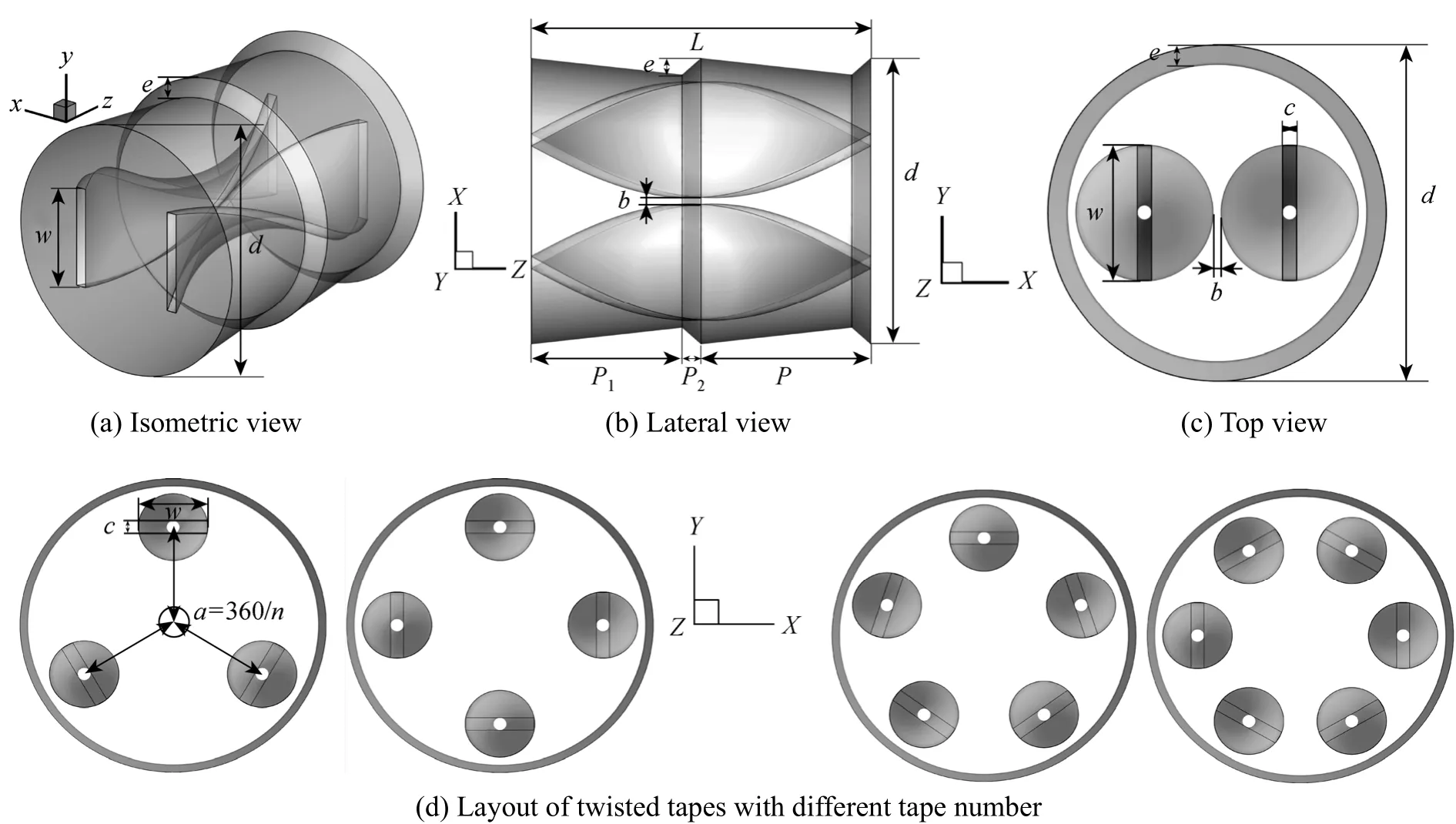
Figure 1 Structure and layout of CDTs

Table 1 Structure parameters for the present study
The present studied geometries and descriptions of CDTs are shown in Fig. 1 and Table 1, respectively.The bare CDs are investigated for comparison, with the identical geometric parameters to that of CDTs.The twin counter-swirling twisted tapes with twist ratio ofy=L/ware placed in the tube passageway. The length and thickness of the twisted tapes areL=22.5 mm andc=0.8 mm, respectively. A gap distance of 0.5 mm between tapes and CDs is manufactured to consider convenient practical application of assembling and disassembling. The width of twisted tape isw=(d-2e-1-b)/2. The adjacent two twisted tapes are in counter-swirl direction and the angle between them is the same. The angle between two adjacent tapes isα=360/n. The effect of different tube pitch length (P),pitch ratio (δ=P1︰P2), rib height (e), gap distance between twisted tapes (b) and tape number (n) as listed in Table 1, will be investigated in this work.
2.2 CFD data reduction
The CFD data is reduced in the following procedure. Firstly, the total heat transfer rate in the tube can be obtained by

whereTwis the average wall temperature, andTbis the average bulk temperature.
The Nusselt number can be calculated as

Finally, the thermal enhancement factor (η) for evaluating overall thermal performance of the enhanced tubes at the constant pumping power can be determined by [21]

2.3 Governing equations and boundary conditions
The problem in this paper is three-dimensional,incompressible, turbulent and steady flow, and the following assumptions or conditions are made to obtain the governing equations: (1) Heat conduction of twisted tapes and natural convection in the tube are neglected; (2) The thickness of tube wall is assumed to be zero; (3) The physical properties of working fluid water is constant.
The governing differential equations in the Cartesian tensor notation used to describe the fluid flow and heat transfer in this paper can be written in the following forms:
Continuity equation:

Momentum equation:

where

Energy equation:

The Renormalization-group (RNG)k-εturbulence model developed by Yakhot and Orszag [22] is used in the present numerical simulation:

wherekis the fluid turbulent kinetic energy,εis the dissipation rate of turbulent kinetic energy,Gkrepresents the generation of turbulent kinetic energy due to the mean velocity gradients,μeffis the effective viscosity as defined byμeff=μ+μt=μ+ρCμk2/ε, and the constants in the model are known asCμ=0.0845,C1ε=1.42,C2ε=1.68,αk=αε=1.393.
No slip condition is applied on tube wall and twisted tapes. Uniform heat flux conditions are imposed on the tube wall. The twisted tapes were set as non-conductive to heat. At the computational domain of inlet and outlet, periodical fully developed condition is imposed, which indicates that the velocity,pressure and temperature gradient repeat themselves in domain as follows:

whereuis the velocity, Δpis the local pressure drop,Θis the temperature gradient,ris the position vector andLis the periodic length vector. The fluid inlet temperature is 303 K. The Reynolds numbers varies from 10000 to 20000.
2.4 Grid generation and numerical method
The grid generations and numerical simulations are performed using commercial CFD software package Gambit 2.2.30 and Fluent 6.3.26, respectively.Fig. 2 presents the mesh generation of the computation domain using hybrid method of size function and boundary layer technique. Tetrahedral grid and hexahedron grid are employed to generate mesh in the interior of tube and boundary layers, respectively. In all cases, the grid is finer close to the wall and the vicinity of the twisted tapes where the temperature and velocity gradients are large. Grid independence tests of three different grid numbers (363375, 552687 and 727861) for CDT withP=11.25 mm,e=0.5 mm,δ=8︰1 andb=0.5 mm atRe=10000-20000 are shown in Fig. 3. It is found that up to 1.17% and 0.94% differences of the Nusselt number (Nu) and friction factor (f) respectively exist between the coarsest mesh and the second finer mesh, and less than 0.15% and 0.83% deviations exist between the two finer meshes, which indicate the middle mesh with grid number of 552687 is suitable for getting a gridindependent solution. Therefore, this grid is adopted in the subsequent simulation with the compromise of computational time and solution precision.

Figure 2 Meshes generation of the CDTs
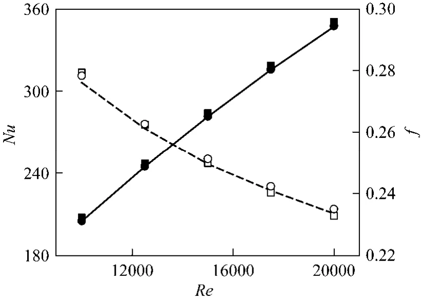
Figure 3 Grid independence tests for different grid number■ 363375-Nu; ● 552687-Nu; 727861-Nu; □ 363375-f;○ 552687-f; 727861-f
In the present study, the differential governing equations are solved with the finite volume method, using pressure based solver with double precision. For the convective and diffusive terms a QUICK discretization scheme is employed while the SIMPLEC algorithm is used for the pressure-velocity coupling. The solution convergence is achieved by a criterion of the residuals below 10-5for continuity and 10-6for other equations.
2.5 Validation using the published correlations
To check the model validity, as presented in Fig. 4,a plain tube model is first validated with the classical Gnielinski equation and Petukhov equation [23], and a model of a plain tube fitted with twin counter- swirling twisted tapes (PT,L=22.5 mm,w=8.75 mm,y=2.57,c=0.8 mm) with the similar geometric parameters is also confirmed with the experimental equations obtained by Eiamsa-ardet al. [10]. The deviation of the plain tube between numerical results and classical empirical equations forNuandfare ±4.61%and ±2.26%, respectively. The numerical results of PT are compared with the Eiamsa-ard equations with the discrepancy of less than ±15.24% forNuand ±11.83%forf. By taking into account the Eiamsa-ard equations agreeing with the experimental data within ±10% and±6% forNuandf, respectively, the present numerical and experimental results are considered in satisfactory agreement in engineering for reasonable accuracy,especially due to the comparative nature and the optimization purposes of the current investigation. The error is mainly from the constant physical properties assumption and the model intrinsic error.

Figure 4 Verifications of the numerical results of the plain tube and PT● plain tube-Nu-numerical; ○ plain tube-f-numerical;plain tube-Nu-Gnielinski; plain tube-f-Petukhow;▲ PT-Nu-numerical; △ PT-f-numerical; ▼ PT-Nu-Eiamsa-ard;▽ PT-f-Eiamsa-ard
3 RESULTS AND DISCUSSION
The numerical analysis of heat and fluid-flows through the CDs and the CDTs will be discussed below,respectively. In the following text, the situation of variable geometric parameters is labeled with an abbreviation.For example, the label “CDT-11.25-0.5-8︰1-b(4.5)”means that the tube pitch length is 11.25 mm, rib height of 0.5 mm, pitch ratio of 8︰1 and the gap between twisted tapes is 4.5 mm for the CDT. The tape number isn=2 unless otherwise stated.
3.1 Heat transfer and flow characteristics for CDs
Figures 5 and 6 show the effect of tube pitch ratio(δ) and rib height (e) on Nusselt number (Nu) and friction factor (f) for CDs with different tube pitch length (P=11.25 mm, 22.5 mm), respectively. In addition, the thermal enhancement factors of the CDs are presented in Fig. 7. From these figures, some general tendencies can be drawn. First, the Nusselt number increases and the friction factor decreases as the Reynolds number increases. Second, the thermal enhancement factors of all CDs are greater than 1 and decrease with the increasingRefor most cases, except for CDs withP=22.5 mm,e=0.5 mm andδ=1︰8 or 5︰4.
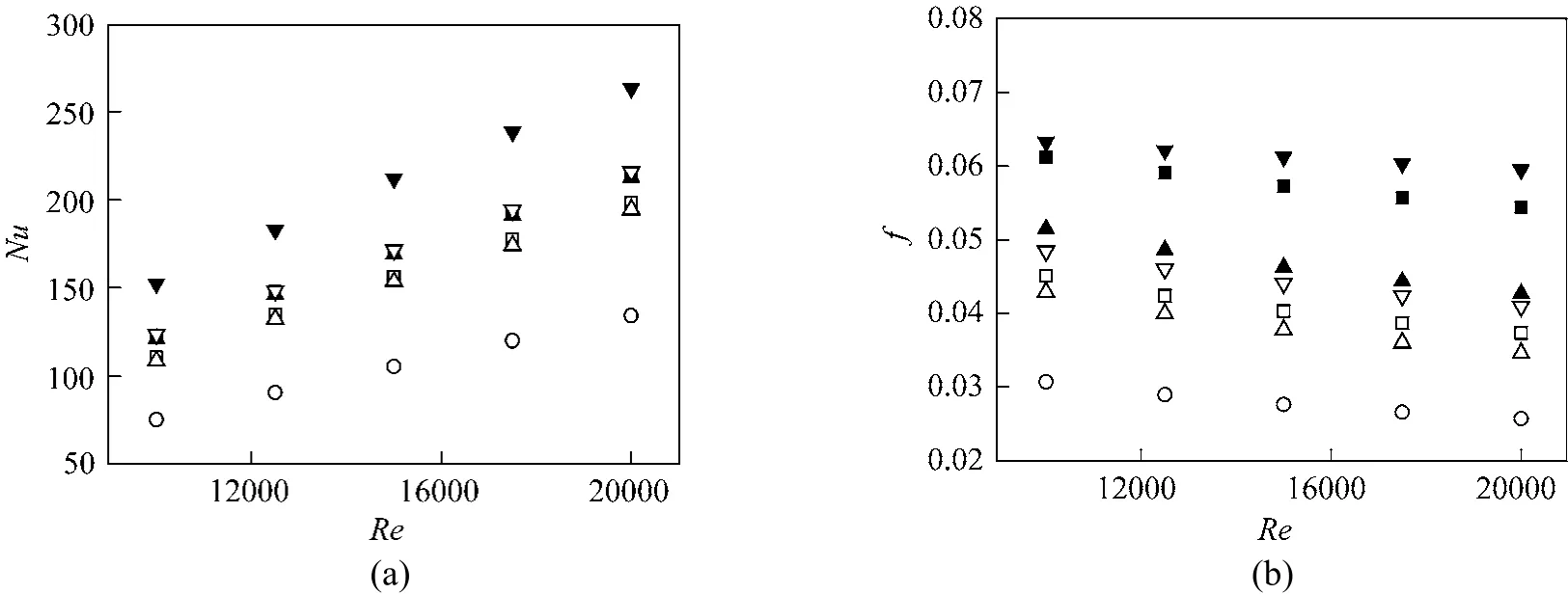
Figure 5 Variations of (a) Nusselt number and (b) friction factor versus Reynolds number for CDs with different P(11.25,22.5 mm) and δ (1︰8, 5︰4, 8︰1) at fixed e (0.5 mm)○ plain tube; □ CD-22.5-1︰8; ■ CD-11.25-1︰8; △ CD-22.5-5︰4; ▲ CD-11.25-5︰4; ▽ CD-22.5-8︰1; ▼ CD-11.25-8︰1
3.1.1Effect of pitch ratio
It is shown in Fig. 5 that the pitch ratio has a strong effect on both Nusselt number and friction factor. As indicated in Fig. 5 (a), at the same pitch length,one can see that the cases ofδ=8︰1 has the largest Nusselt number, the next is the cases ofδ=1︰8, and then the cases ofδ=5︰4. It is noted that there is only a tiny difference of the Nusselt number between the cases ofδ=1︰8 and 5︰4. Meanwhile, it is observed from Fig. 5 (b) that the friction factor decreases as the pitch ratio increases from 1︰8 to 5︰4 and increases as the pitch ratio increases from 5︰4 to 8︰1. As illustrated in Fig. 7 (a), the thermal enhancement factor increases as the pitch ratio increases from 1︰8 to 8︰1 at the same pitch length, which indicates that the longer the converging pitch is, the better the overall thermal performance.
3.1.2Effect of tube pitch

Figure 6 Variations of (a) Nusselt number and (b) friction factor versus Reynolds number for CDs with different P(11.25,22.5 mm) and e (0.5, 0.8, 1.1 mm) at fixed δ (8︰1)○ plain tube; □ CD-22.5-0.5; ■ CD-11.25-0.5; △ CD-22.5-0.8; ▲ CD-11.25-0.8; ▽ CD-22.5-1.1; ▼ CD-11.25-1.1

Figure 7 Variations of η versus Reynolds number for (a) CDs with different P (11.25, 22.5 mm) and δ (1︰8, 5︰4, 8︰1) at fixed e (0.5 mm) and (b) CDs with different P (11.25, 22.5 mm) and e (0.5, 0.8, 1.1 mm) at fixed δ (8︰1)
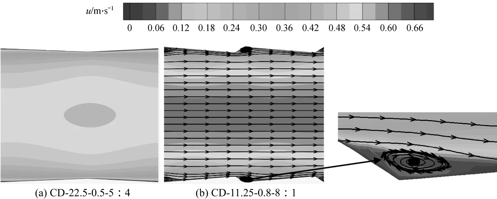
Figure 8 Contour plots of velocity and streamlines for CD-22.5-0.5-5︰4 and CD-11.25-0.8-8︰1 at Re=10000
It is seen from Figs. 5, 6 that the higher Nusselt number and friction factor are obtained for the cases withP=11.25 mm, due to high turbulence intensity imparted to the flow between two ribs, while the lower ones are gained for the cases withP=22.5 mm.The increases in Nusselt number and friction factor forP=11.25 mm are in range of 10.8%-25.9% and 36%-74% aboveP=22.5 mm. Moreover, it can be observed from Fig. 7 that the shorter the tube pitch length is, the better the thermal enhancement factor becomes, except for the case ofP=11.25 mm,e=0.5 mm andδ=1︰8.
3.1.3Effect of rib height
Rib height is an important factor of rough surfaces using protrusions mounted on them to get heat transfer enhancement. A suitable rib height with appropriate pressure drop is in favor of improving the thermal enhancement factor. It is seen that from Fig. 6 that both Nusselt number and friction factor increase with increasing rib height in all cases. This is because,by increasing rib height, the local heat transfer near the wall is improved because the turbulence intensity induced by ribs is intensified. One can see from Fig. 7(b) that the cases ofe=0.5 mm have the best thermal enhancement factor at most of the Reynolds number withη=1.38-1.59, the next is the cases ofe=0.8 mm withη=1.34-1.59, and then the cases ofe=1.1 mm withη=1.23-1.48. Meanwhile, the cases withP=11.25 mm yield a better thermal performance than the cases withP=22.5 mm at the same rib height.
3.1.4Flow structure
Contour plots of velocity and streamlines for CD-22.5-0.5-5︰4 and CD-11.25-0.8-8︰1 atRe=10000 onY=0 mm plane are displayed in Fig. 8. It can be visible from Fig. 8 (a) that due to the variation of the tube cross section, the velocity increases in the converging sections and decreases in the diverging sections. Meanwhile, the pressure decreases in the converging sections and increases in the diverging sections, according to the Bernoulli equation [24].Hence, the converging section is more contributive than the diverging section to the benefit of heat transfer enhancement with the promoted flow turbulence.As seen in Fig. 8 (b), owing to the direction of fluid flow changing abruptly under the effect of the axial pressure gradient in the near wall zone, a pair of transverse vortices is generated because of flow separation in the diverging section and effectively employed in the converging section to thin the boundary layer and improve turbulence. Consequently, the CDs give higher heat transfer rate than that of the plain tube.

Figure 9 Contour plots of turbulence intensity for plain tube and CDs with different geometric parameters at Re=10000

Figure 10 Variations of (a) Nusselt number and (b) friction factor versus Reynolds number for CDTs with different P(11.25, 22.5 mm ) and different δ (1︰8, 5︰4, 8︰1) at fixed e (0.5 mm) and b (0.5 mm)○ plain tube; □ CDT-22.5-0.5-1︰8; ● PT; △ CDT-22.5-0.5-5︰4; ■ CDT-11.25-0.5-1︰8; ▽ CDT-22.5-0.5-8︰1;▲ CDT-11.25-0.5-5︰4; ▼ CDT-11.25-0.5-8︰1
Contour plots of turbulence intensity onY=0 mm plane are displayed in Fig. 9 for CDs with different geometric parameters, atRe=10000. It demonstrates that the CDs can effectively enhance the turbulence intensity in the near wall zone but can’t further improve the turbulence intensity in the mainstream. In addition, higher turbulence intensity is seen in the converging sections rather than the diverging sections,which is the reason why the CDs with the longer converging pitch show higher heat transfer rate. A larger turbulence intensity zone is found in the cases with higher rib, resulting in higher heat transfer rate and larger pressure drop.
As discussed above, when bare CDs are employed, it is concluded that the Nusselt number and friction factor of CDs are higher than that of the plain tube at around 44.4%-167.6% and 34.7%-511.6%,respectively. Moreover, the thermal enhancement factors for CDs with varying geometric parameters are in range of 1.23-1.59.
3.2 Heat transfer and flow characteristics for CDTs
Figures 10 and 11 illustrate the effects of tube pitch ratio (δ), rib height (e) and gap distance between twisted tapes (b) on variations of Nusselt number and friction factorversusReynolds number for CDTs withP=11.25 mm and 22.5 mm, respectively. Except for the cases of “CDT-11.25-0.5-8︰1-b(4.5)” and“CDT-11.25-0.5-8︰1-b(8.5)”, the gap distance between twisted tapes for all other cases isb=0.5 mm unless otherwise stated. Twisted tape with a smaller twist ratio has a better thermal performance than the one with a bigger twist ratio [10], so the twist ratio for all cases withb=0.5 mm approximates toy=2.5. A plain tube fitted with twin twisted tapes (PT) is also presented for comparisons. The thermal enhancement factors for the CDTs are presented in Fig. 12. In the figures, it is clearly seen that the thermal enhancement factor of all CDTs are greater than 1 but smaller than their counterparts of CDs, and the thermal enhancement factor decreases with increasing Reynolds number for most cases, except for some cases withe=0.5 mm at low Reynolds number.
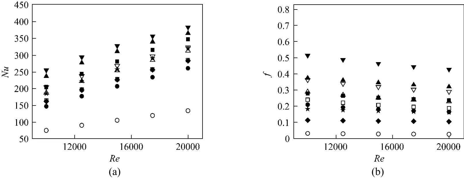
Figure 11 Variations of (a) Nusselt number and (b) friction factor versus Reynolds number for CDTs with different P(11.25, 22.5 mm ), different e (0.5, 0.8, 1.1 mm) and different b (0.5, 4.5, 8.5 mm) at fixed pitch ratio δ (8︰1)○ plain tube; □ CDT-22.5-0.5; ● PT; △ CDT-22.5-0.8; ■ CDT-11.25-0.5; ▽ CDT-22.5-1.1; ▲ CDT-11.25-0.8; ★ CDT-11.25-0.5-b(4.5);▼ CDT-11.25-1.1; ◆ CDT-11.25-0.5-b(8.5)
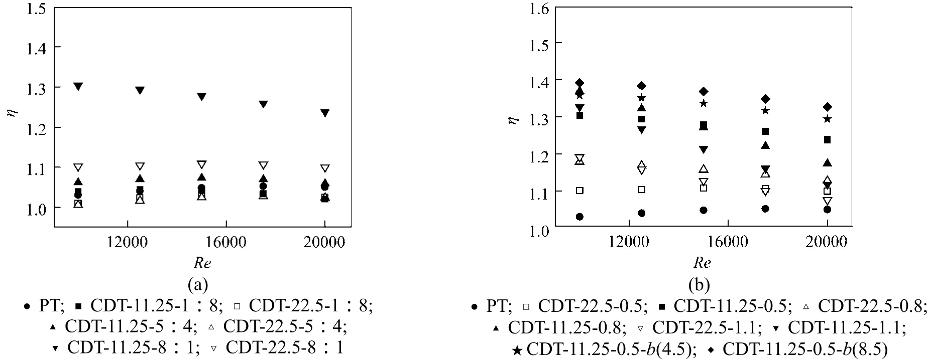
Figure 12 Variations of η versus Reynolds number for (a) CDTs with different P (11.25, 22.5mm ) and different δ (1︰8, 5︰4,8︰1) at fixed e (0.5 mm) and b (0.5 mm); (b) CDTs with different P (11.25, 22.5 mm ), different e (0.5, 0.8, 1.1 mm) and different b (0.5, 4.5, 8.5 mm) at fixed pitch ratio δ (8︰1)
3.2.1Effect of pitch ratio
It is clearly seen from Fig. 10, at bothP=11.25 and 22.5 mm, the cases withδ=8︰1 have the largest Nusselt number than those withδ=5︰4 and 1︰8. AtP=22.5 mm, it is presented in Fig. 10 (a) that the Nusselt number of the cases withδ=5︰4 and 1︰8 almost equal to that of the PT. The reason is that the CDTs have rib structures compared with the PT, leading to a narrower width of twisted tape. Then, the heat transfer reduction resulting from the narrower twisted tape counteracts the heat transfer enhancement of the rib effect. Whereas, due to the increase of pitch number, atP=11.25 mm, one can see from Fig. 10 (a) that the cases withδ=5︰4 and 1︰8 have larger Nusselt number than the PT. As shown in Fig. 10 (b), at the same pitch length, the cases ofδ=8︰1 have the largest friction factor, the next is the cases ofδ=1︰8,and then is the cases ofδ=5︰4, and the last is the PT.As illustrated in Fig. 12 (a), whenP=22.5 mm, the case withδ=8︰1 has the best thermal performance,the second is the PT, and the last two are the cases ofδ=5︰4 and 1︰8. WhenP=11.25 mm, the thermal enhancement factor of the cases withδ=8︰1 and 5︰4 are higher than that of the PT, while the cases ofδ=1︰8 just have better performance than the PT at low Reynolds number. Generally, the longer the converging length is, the better the thermal performance.
3.2.2Effect of tube pitch

Figure 13 Variations of (a) Nusselt number and (b) friction factor for CDTs with different number twisted tapes versus Reynolds numbern: ● 2; ▲ 3; ▼ 4; 5; 6
With other geometric parameters fixed, it is observed from Fig. 10 (a) and Fig. 11 (a) that the cases withP=11.25 mm show a large augment on Nusselt number over that of the cases withP=22.5 mm around 4.7% to 26.9%, especially for the cases withδ=8︰1. It is found in Figs. 10 (b) and 11 (b) that the increase in friction factor for cases withP=11.25 mm is in a range of 7.4% to 48% over the cases withP=22.5 mm. Besides, it is clearly seen from Fig. 12 that the shorter the pitch length is, the better the thermal enhancement factor behaves, except for the cases withP=11.25 mm,e=0.5 mm andδ=1︰8 atRe=20000 due to large pressure drop.
3.2.3Effect of rib height
It is illustrated in Fig. 11 that the Nusselt number and friction factor are found to noticeably increase with increasing rib height by fixing other geometric parameters. The increment of Nusselt number from the cases ofe=0.5 mm to the cases ofe=0.8 mm is greater than that from the cases ofe=0.8 mm to the cases ofe=1.1 mm, while the variations of friction factor tend to be opposite. Consequently, as shown in Fig. 12 (b), the cases withe=0.8 mm have the best thermal enhancement factor at most of the Reynolds number. This is because in the CDTs, the heat transfer enhancement in not only dominated by the rib configuration but also controlled by the swirl flow induced by the twin twisted tapes, so the best rib height in terms of the overall thermal performance is different from that in bare CDs. In addition, it is seen from Fig. 12 (b) that all cases of the CDTs exhibit better performance than the PT.
3.2.4Effect of gap distance between twisted tapes
Effect of the gap distance between twisted tapes on the heat transfer and fluid flow behaviors of the CDTs withP=11.25 mm,e=0.5 mm andδ=8︰1 is presented in Fig. 11. As the gap distance increases,both the Nusselt number and the friction factor decrease, and the decrement of the Nusselt number is lower than that of the friction factor. Hence, as seen in Fig. 12 (b), the thermal enhancement factor of the CDTs increases with the increase of gap distance. The reason is that the major thermal resistance and flow resistance in turbulent flow locate in the near wall zone and the mainstream zone, respectively. Consequently, a higher thermal performance (the maximumη=1.39) can be obtained by placing loose-fit twisted tapes in the near wall zone, reducing the thermal resistance as well as avoiding too much body resistance.
3.2.5Effect of twisted tape number
In order to know whether the thermal enhancement factor can be further improved by placing more twisted tapes in the near wall zone, the influence of the tape number on the heat transfer and flow resistance behaviors of CDTs withP=11.25 mm,e=0.5 mm,δ=8︰1 andb=8.5 is displayed in Figs. 13 (a)and 13 (b), respectively. It can be found that both the Nusselt number and friction factor rises with increasing tape number. This is because that the more number twisted tapes help to create more longitudinal vortices giving better mixing between the mainstream and the near wall regions and resulting in higher turbulence intensity and temperature gradient near the wall. Atn=3, 4, 5 and 6, the increases in Nusselt number are in a range of 4.5%-5%, 8.9%-9.5%, 16.4%-16.9%,22.5%-23.5%, respectively, over atn=2. However,the increments in friction factor atn=3, 4, 5 and 6,are respectively 30.7%-32.7%, 63.6%-69.7%, 102.7%-113%, 141%-157.5% over atn=2. As seen from Fig.14, atn=2, 3, 4, 5 and 6, the variation ranges of the thermal enhancement factors with Reynolds number areη=1.33-1.39, 1.27-1.32, 1.23-1.27, 1.22-1.26,1.21-1.25. This is due to the fact that the increment in flow resistance is higher than that in heat transfer rate with increasing tape number.
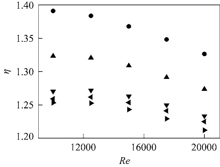
Figure 14 Variations of η for CDTs with different number twisted tapes versus Reynolds numbern: ● 2; ▲ 3; ▼ 4; 5; 6
3.2.6Flow structure
Contour plots of velocity and streamlines for CDT-22.5-0.5-5︰4 and CDT-11.25-0.8-8︰1 are presented in Fig. 15. The figure shows that two types of flows are generated in tube. The one is straight flow near the tube wall, and the other is swirl flow induced by the twin twisted tapes which can improve fluid mixing between the mainstream zone and the near wall zone. The CDTs can simultaneously employ the transverse vortices from CDs and longitudinal vortices from twin twisted tapes to enhance heat transfer rate in a superimposed way, but they have higher pressure drop than their counterparts of CDs due to more body resistance. Consequently, compared with the bare CDs,the CDTs have higher heat transfer rate but have lower thermal enhancement factor. As Reynolds number increases, in general, the increase of pressure drop in the CDTs is much higher than that in heat transfer.Hence, generally, the overall thermal performance of the CDTs decreases as Reynolds number increases.
Contour plots of turbulence intensity onY=0 mm plane atRe=10000 are illustrated in Fig. 16 for the CDTs with different geometric parameters. It is clearly seen that all CDTs have more intense and homogeneous turbulence intensity distribution than the plain tube, bare CDs and PT resulting from the double effect of the CDs and twin twisted tapes on the flow structure. The CDTs can not only improve turbulence intensity in the near wall zone but also in the mainstream zone. In other words, the heat transfer and flow characteristics are dominated by both the rib effect of CDs and the swirl flow effect of twisted tapes which govern the boundary layer separation and reattachment,secondary flow and flow recirculation in the tube.
Contour plots of velocity vector and turbulence intensity for the CDTs (P1=11.25 mm,e=0.5 mm,δ=8︰1) with different gap distance (b) and tape number (n) onZ=11.25 mm plane atRe=10000 are presented in Fig. 17. One can see from Figs. 17 (a)-(c),the turbulence intensity decreases and distributes unevenly as gap distance increases, which indicates that the heat transfer deteriorates. This is because that the flow swirls on the tape decrease as the gap distance increases, and the axisymmetric swirl streams impinged to the tube wall become less and less, thus the mixing is increasingly inhomogeneous as the gap distance increases. Nonetheless, a lower pressure drop as well as a higher thermal enhancement factor can be gained for the cases with loose-fit tapes. It is observed from Figs. 17 (c)-(g) that in the near wall zone, the zones where the streams flow toward the wall have higher turbulence intensity than that in the zones where the streams flow away from the wall. In addition, the turbulence intensity increases with increasing tape number, which indicates that the heat transfer can be improved with the increase of tape number. Similarly, the more increase in pressure drop is accompanied by more tapes. Thus, the less the tape number, the better the overall thermal performance is.
In conclusion, when the twisted tapes are used simultaneously in combination with CDs, it is observed from Figs. 10-14, the heat transfer rate and friction factor of the CDTs are higher than their counterparts of bare CDs around 6.3%-35.7% and 1.75-5.3 times, respectively. In addition, the thermal enhancement factor for the CDTs is between 1.01-1.39, which is lower than the corresponding bare CDs withη=1.23-1.59. The CDTs can make the distribution of thermal resistance and turbulence intensity to be more homogeneous to obtain a higher heat transfer rate. As a means of overcoming the shortcomings associated with the heat transfer enhancement only in the near wall zone by the bare CDs, the CDTs are promising heat exchangers aiming at enhancing heat transfer rate to the full extent with not too much pressure drop.

Figure 15 Contour plots of velocity and streamlines at Re=10000
3.3 Correlations
Figure 18 presents the comparisons between the numerical values and those predicted by the respective correlations in Table 2. In the figures, the majority of the fitted values are agreeing with the numerical data within ±15 for both Nusselt number and friction factor.
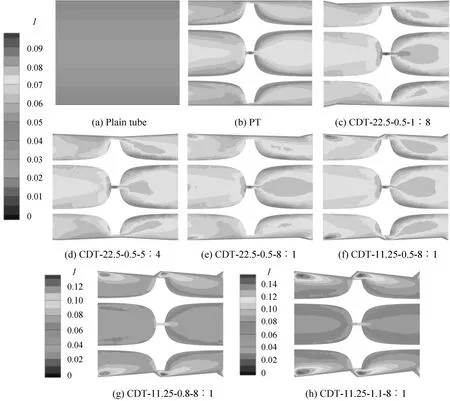
Figure 16 Contour plots of turbulence intensity for plain tube, PT and CDTs with different geometric parameters at Re=10000
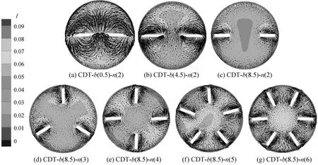
Figure 17 Plots of velocity vectors and turbulence intensity for CDTs with different b and n at Re=10000

Figure 18 Comparisons between numerical values and predicted values○ CDs; □ CDTs

Table 2 Summary of correlations for Nusselt number and friction factor
4 CONCLUSIONS
In this investigation, a numerical prediction has been conducted to study the heat transfer and flow characteristics of CDs and CDTs with varying geometric parameters in turbulent flow. The following are the conclusions of the present paper:
(1) A finite volume method with Renormalizationgroup (RNG)k-εturbulence model is used in this study.The computations present that the predicted values are in good agreement with the results of the previous research. It is shown that the geometric parameters have an important influence on the thermal performances of both the CDs and the CDTs. By geometric optimizing, considerably enhanced heat transfer rate is achievable for both by decreasing the pitch length, by increasing the rib height, and by increasing the pitch ratio. In addition, the heat transfer rate of the CDTs increases with decreasing gap distance and increasing tape number.
(2) The obtained results show that, for the CDs,the case withP=11.25 mm,e=0.5 mm andδ=8︰1 has the best thermal performance under the investigated geometric parameters. For the CDTs, the case withP=11.25 mm,e=0.5 mm,δ=8︰1 andb=8.5 mm has the best thermal performance. If the goal is to pursue the maximal heat transfer rate enhancement,the CDTs with tight-fit twisted tapes should be in consideration. If a better overall thermal performance is sought, the bare CDs (the largestη=1.59) or CDTs with loose-fit twisted tapes (the largestη=1.39)maybe worth of commendation.
(3) The contour plots of predicted velocity,turbulence intensity and streamlines are presented for further understanding of the mechanism of compound heat transfer enhancement. It reveals that the CDs mainly promote turbulence intensity and heat transfer in the near wall zone. While, the simultaneous employment of the CDs and twin twisted tapes not only homogenizes turbulence intensity and enhances heat transfer rate in the near wall zone, but also does in the mainstream zone. In conclusion, the CDTs hold promise for practical applications.
NOMENCLATURE
bgap distance between twisted tapes, mm
cthickness of twisted tape, mm
cpspecific heat at constant pressure, J·kg-1·K-1dtube diameter, mm
erib height, mm
ffriction factor [f=2dΔp/(lρu2)]
hheat transfer coefficient, W·m-2·K-1
Llength of the tube section, mm
Lperiodic length vector
NuNusselt number (Nu=hd/λ)
Ppitch length, mm
PrPrandtl number (Pr=cpμ/λ)
P1length of converging section, mm
P2length of diverging section, mm
ΔPpressure drop, Pa
Qheat transfer rate, W
ReReynolds number (Re=duρ/μ)
rposition vector
Ttemperature, K
wtape width, mm
ytwist ratio
δpitch ratio (δ=P1/P2)
Θ dimensionless temperature gradient
λ fluid thermal conductivity, W·m-1·K-1
μ fluid dynamic viscosity, kg·m-1·s-1
ρ fluid density, kg·m-3
Subscripts
b bulk
i inlet
o outlet
p plain tube
w tube wall
1 Bergles, A.E., “ExHFT for fourth generation heat transfer technology”, Exp. Therm. Fluid Sci., 26 (2-4), 335-344 (2002).
2 Li, J., “Study on heat transfer performance and flow resistance performance of many kinds of heat transfer enhanced tube”, Master Thesis, South China University of Technology, Guangzhou (2000).(in Chinese)
3 Chen, Y., Deng, X.H., Ding, X.J., Wang, Y.J., “Convection heat transfer of fully developed turbulent flow in shaped tubes with a new concept”, Int. Commun. Heat Mass Transfer, 31 (3), 355-364 (2004).
4 Manglik, R.M., Bergles, A.E., “Heat transfer and pressure drop correlations for twisted-tape inserts in isothermal tubes: part I—Laminar flows”, J. Heat Transfer, 115 (4), 881-889 (1993).
5 Manglik, R.M., Bergles, A.E., “Heat transfer and pressure drop correlations for twisted-tape inserts in isothermal tubes: part II—Transition and turbulent flows”, J. Heat Transfer, 115 (4), 890-897 (1993).
6 Saha, S.K., Gaitonde, U.N., Date, A.W., “Heat transfer and pressure drop characteristics of laminar flow in a circular tube fitted with regularly spaced twisted-tape elements”, Exp. Therm. Fluid Sci., 2(3), 310-322 (1989).
7 Saha, S.K., Gaitonde, U.N., Date, A.W., “Heat transfer and pressure drop characteristics of turbulent flow in a circular tube fitted with regularly spaced twisted-tape elements”, Exp. Therm. Fluid Sci., 3(6), 632-640 (1990).
8 Abu-Khader, M.M., “Further understanding of twisted tape effects as tube insert for heat transfer enhancement”, Heat Mass Transfer, 43(2), 123-134 (2006).
9 Wang, Y.J., Hou, M.L., Deng, X.H., Li, L., Huang, C., Huang, H.Y.,Zhang, G.F., Chen, C.H., Huang, W.J., “Configuration optimization of regularly spaced short-length twisted tape in a circular tube to enhance turbulent heat transfer using CFD modeling”, Appl. Therm.Eng., 31 (6-7), 1141-1149 (2011).
10 Eiamsa-ard, S., Thianpong, C., Eiamsa-ard, P., “Turbulent heat transfer enhancement by counter/co-swirling flow in a tube fitted with twin twisted tapes”, Exp. Therm. Fluid Sci., 34 (1), 53-62 (2010).
11 Eiamsa-ard, S., Promvonge, P., “Thermal characteristics in round tube fitted with serrated twisted tape”, Appl. Therm. Eng., 30 (13),1673-1682 (2010).
12 Chang, S.W., Yang, T.L., Liou, J.S., “Heat transfer and pressure drop in tube with broken twisted tape insert”, Exp. Therm. Fluid Sci., 32(2), 489-501 (2007).
13 Guo, J., Fan, A.W., Zhang, X.Y., Liu, W., “A numerical study on heat transfer and friction factor characteristics of laminar flow in a circular tube fitted with center-cleared twisted tape”, Int. J. Therm. Sci.,50 (7), 1263-1270 (2011).
14 Murugesan, P., Mayilsamy, K., Suresh, S., “Turbulent heat transfer and pressure drop in tube fitted with square-cut twisted tape”, Chin.J. Chem. Eng., 18 (4), 609-617 (2010).
15 Zimparov, V., “Enhancement of heat transfer by a combination of three-start spirally corrugated tubes with a twisted tape”, Int. J. Heat Mass Transfer, 44 (3), 551-574 (2001).
16 Zimparov, V., “Enhancement of heat transfer by a combination of a single-start spirally corrugated tubes with a twisted tape”, Exp. Therm.Fluid Sci., 25 (7), 535-546 (2002).
17 Nagarajan, P.K., Mukkamala, Y., Sivashanmugam, P., “Studies on heat transfer and friction factor characteristics of turbulent flow through a micro-finned tube fitted with left-right inserts”, Appl.Therm. Eng., 30 (13), 1666-1672 (2010).
18 Promvonge, P., “Thermal augmentation in circular tube with twisted tape and wire coil turbulators”, Energy Convers. Manage., 49 (11),2949-2955 (2008).
19 Eiamsa-ard, S., Nivesrangsan, P., Chokphoemphun, S., Promvonge,P., “Influence of combined non-uniform wire coil and twisted tape inserts on thermal performance characteristics”, Int. Commun. Heat Mass Transfer, 37 (7), 850-856 (2010).
20 Bharadwaj, P., Khondge, A.D., Date, A.W., “Heat transfer and pressure drop in a spirally grooved tube with twisted tape insert”, Int. J.Heat Mass Transfer, 52 (7-8), 1938-1944 (2009).
21 Webb, R.L., Eckert, E.R.G., “Application of rough surfaces to heat exchanger design”, Int. J. Heat Mass Transfer, 15 (9), 1647-1658(1972).
22 Yakhot, V., Orszag, S.A., “Renormalised group analysis of turbulence: I. Basic theory”, J. Sci. Comput., 1 (1), 3-51 (1986).
23 Incropera, F.P., Witt, P.D., Bergman, T.L., Lavine, A.S., Fundamentals of Heat and Mass Transfer, 6th edition, John-Wiley & Sons,Hoboken (2006).
24 Durst, F., Fluid Mechanics, Springer, Berlin (2008).
猜你喜欢
杂志排行
Chinese Journal of Chemical Engineering的其它文章
- Experimental and Modelling Studies of Biomass Pyrolysis*
- Synergistic Multilayer Adsorption for Low Concentration Dyestuffs by Biomass
- Kinetics of Photocatalytic Degradation of Gaseous Organic Compounds on Modified TiO2/AC Composite Photocatalyst*
- Techno-economic Analysis of Distributed Hydrogen Production from Natural Gas
- Error Analysis of Adsorption Isotherm Models for Acid Dyes onto Bamboo Derived Activated Carbon
- Issues in Freeze Drying of Aqueous Solutions*
