Preparation of Laser Cladding Coating Undercooling Cu-based Alloy and Co on Non-equilibrium Solidification Structure
2024-04-11TIANXumingCAOShichaoHOUKaiHOUXiaopengWANGHongfuZHANGYu
TIAN Xuming ,CAO Shichao ,HOU Kai ,HOU Xiaopeng ,WANG Hongfu ,ZHANG Yu
(1.Department of Outpatient,Xinzhou People’s Hospital,Xinzhou 034099,China;2.School of Mechanical Engineering,North University of China,Taiyuan 030051,China;3.Department of Neurosurgery,Xinzhou People’s Hospital,Xinzhou 034099,China;4.Department of Orthopedics,Xinzhou People’s Hospital,Xinzhou 034099,China)
Abstract: The effect of the gradient content of Co element on the solidification process of Cu-based alloy under deep under cooling conditions was explored.The non-equilibrium solidification structure of the under cooled alloy samples were analyzed.It is found that the rapidly solidified alloy has undergone twice grain refinement during the undercooling process.Characterization and significance of the maximum undercooling refinement structure of Cu60Ni35Co5 at T=253 K were analyzed.High-density defects were observed,such as dislocations,stacking faults networks,and twinning structures.The standard FCC diffraction pattern represents that it is still a single-phase structure.Based on the metallographic diagram,EBSD and TEM data analysis,it is illustrated that the occurrence of grain refinement under high undercooling is due to stress induced recrystallization.In addition,the laser cladding technology is used to coat Co-based alloy (Stellite12) coating on 304 stainless steel substrate;the microstructure of the coating cross-section was analyzed.It was found that the microstructure of the cross-section is presented as columnar crystals,planar crystals,and disordered growth direction,so that the coating has better hardness and wear resistance.By electrochemical corrosion of the substrate and coating,it can be seen that the Co and Cr elements present in the coating are more likely to form a dense passivation film,which improved the corrosion resistance of the coating.
Key words: non-equilibrium solidification structure;undercooling;recrystallization;laser cladding coating
1 Introduction
Grain refinement significantly improved the structural properties of alloy structure[1,2],and the refined metallic materials have a wide range of applications in the field of medical devices[3,4].Researchers have focused their attention on the preparation of such alloys.Walker[5]discovered grain refinement in under cooled pure Ni.The grain refinement has been found in a variety of metals or alloys[6-10],which is great significance for the optimal use of medical devices.Stainless steel medical devices have great market potential.The development of stainless medical devices by the continuous improvement of the industry and the constant innovation of product technology is very impressive.The grain refinement alloys meet clinical needs.At the same time,the laser cladding technology also brings new opportunities for the development of stainless steel medical devices,such as in the surface modification of medical devices,surface alloying,ceramics,etc.This research provides new ideas and possibilities for the development of stainless steel medical devices.
Researchers have found grain refinement at low and high under cooling through decades[9,11-14].It was proposed dendrite fusion mechanism for grain refinement in low undercooling alloys.However,there were different views on the mechanism of grain refinement of alloy structures at high undercooling.Kattamis suggested that the grain refinement at high under cooling was caused by superheated fusion of dendrites[15].Cochrane explored Cu-Sn and Cu-O alloys.They found that re-crystallization lead to microstructure refinement at high under cooling[16].It was believed that dendrite fusion led to microstructure refinement at high undercooling.Li[13]and Liu[17]found that the grain refinement structure in the deep undercooling rapid solidification structures of Ni-Cu and DD3 alloy systems had the characteristics of recrystallization.They believed that re-crystallization lead to structure refinement.Researchers have proposed a number of mechanisms to try to explain the grain refinement of alloy structures under high undercooling:dendrite remelting[13,14],recrystallization[18],critical velocity theory[19],instability of dendrite growth[20],kinetic nucleation mechanism[21].There was no consensus in the academic community on the explanation of grain refinement at high undercooling.
In this paper,the process of Cu60Ni35Co5 alloy is investigated under high undercooling conditions during the late stage of non-equilibrium solidification on the basis of stress-induced recrystallisation.
The dynamic evolution was observed by high speed camera to measure the solidification front and the crystal morphology information.The level of substructural defects at ∆T=253 K was illustrated.The velocity and tissue transformations of Cu-Ni-Co alloys were investigated and analyzed by obtaining the experimental data.The effect of the Co element on the solidification was explored by the EBSD and TEM.
At ∆T=253 K,the researchers illustrated the solidification front by a high-speed camera.To observe the dynamic evolution process of the alloy microstructure,the crystal morphology information and the level of sub-structural defects was analyzed.
2 Experimental
Pure Cu particles (99.99%),pure Ni particles(99.99%) and pure Co particles (99.99%) are melted in proportion to the composition of each alloy to prepare the master alloy.High purity Ar was used as a protective gas during the melting process.The melting process was repeated three times to ensure the uniformity of the alloy composition.The quartz tube and the alloy specimen were cleaned with alcohol in an ultrasonic cleaner for 10 minutes for initial purification.The cleaned alloy specimen and B2O3(20%) were put into the quartz tube,which was mounted in a highfrequency induction coil and heated,with the vacuum pumped up to 3×10⁻³Pa and the gas(Ar) backfilled to 5×10⁻²Pa.The infrared thermometer record temperature changes throughout the process with a corresponding time of 1 millisecond.While at the same time a high-speed camera (OLYMPUS I-speed3)was used to record temperature in order to capture the rapid solidification of the undercooled alloy.It is necessary to approximately 800 ℃ to completely melt the B2O3in order to encapsulate the alloy.It is slowly heated to 100 to 200 K above the melting point of the alloy.Then hold for 15 minutes to further decompose the impurities.The alloy was cooled until the desired undercooling is achieved.As shown in Fig.1,it is the experimental diagram for deep under cooling rapid solidification.The undercooled solidified samples of the alloy were cut,inlaid and polished.Then the samples were corroded in a mixture of 20 mL of HCL and 20 mL of HNO3.The morphology of the undercooled microstructure was observed and photographed by an optical microscope (Olympus GX71).The specimens were polished with Al2O3colloidal suspension on a vibratory polishing machine to remove the stress layer from the specimen surface.

Fig.1 Schematic diagram of the experiment
The grain boundary of the microstructure was observed by electron backscatter diffraction.The transmission electron microscope observed the micro structural features.The microhardness of the specimens was measured on a HMV-2T microhardness tester with a load of 490.3 mN,and at least 20 points were measured for each specimen to ensure the accuracy of the measurement results.
3 Results and discussion
3.1 Microstructure analysis
The solidified samples of Cu60Ni35Co5 alloy with under cooling 10 K were obtained by the fluxing method.It is found that the morphology features were divided into the following typical transformation processes:
When ∆T<65 K,the microstructure morphology of Cu60Ni35Co5 alloy was coarse dendrite,and a large number of developed secondary dendrite had grown on the dendrite trunk,as shown in Fig.2(a).Dendrites had grown in a certain direction and in local areas,as shown by the purple line.However,there was no specific growth direction.The dendrite was relatively loose.The dendrite size was large.It decreased with the increase of undercooling.
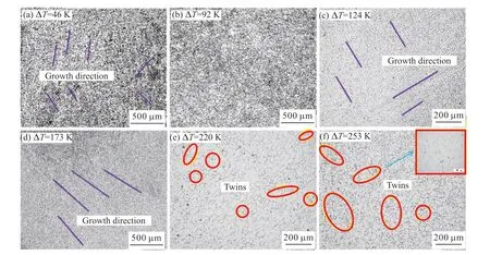
Fig.2 Microstructure of Cu60Ni35Co5 alloy
When 65 K<∆T<143 K,the coarse dendrites almost disappeared.The microstructure of the alloy contained a large number of equiaxed grains and a small number of short dendrites.In the alloy structure at ∆T=91 K,it was almost completely fine equiaxed grains.The equiaxed grain boundary characteristics are shown in Fig.2(b).The average grain size was significantly reduced.Most grain sizes were below 60 μm.The first grain refinement occurred in the alloy.
When 14 K<∆T<220 K,with the further improvement of undercooling,the refined equiaxed grains disappeared.Compared with the coarse dendrite morphology in the low undercooling structure with ∆T<65 K,the alloy structure in this undercooling range was also dendrite morphology.But the diameter is relatively low.The directional growth characteristics were shown in the purple line in Figs.2(c) and 2(d).In addition,the directional fine dendrite network was much finer than the coarse dendrite network.
When ∆T>220 K,the microstructure morphology has not shown the development of extremel fine dendrite network.A large number of equiaxed grains were found to occur in the microstructure,as shown in Figs.2(e) and 2(f).The second grain refinement had occurred during the undercooling range.Compared with the first grain refinement,there was a big difference in the refined grain.The equiaxed grain boundaries were relatively straight.There are a large number of annealing twins (marked by yellow circles),which are typical features of recrystallization.
The microstructure morphology of Cu60Ni35Co5 alloy throughout the under cooling range was found.The transformation process was “coarse dendrite -equiaxed crystal -oriented fine dendrite -equiaxed crystal”.The morphology of twice dendrite and twice refined equiaxed crystal appeared in the microstructure evolution of the alloy.But there were great differences.The BCT[22]mode illustrated the reasons for this difference.BCT model divided the dendrite tip undercooling ∆Tinto four under cooling components.The thermal undercooling (∆Tt) was controlled by thermal diffusion,the solute undercooling (∆Tc) was formed by solute diffusion,the curvature undercooling(∆Tr) was caused by Gibbs-Thomson effect,and the dynamic undercooling (∆Tk) was caused by kinetics at the melt solidification interface:
This model was used to analyze the transformation process of microstructure and morphology of Cu60Ni35Co5 alloy.
When ∆T<65 K,the alloy was confined to a very narrow area around it.The coarse dendrite morphology was formed.When 65 K<∆T<143 K,the influence of thermal diffusion gradually increases with undercooling.The first grain refinement occurred during the range of undercooling.When 114 K<∆T<220 K,∆Ttincreased significantly.The dendrites had grown along the direction of thermal diffusion.In addition,∆Tkhas a great impact on the dendrite diameter.When ∆T>220 K,secondary grain refinement occurred in the alloy.The grain size was relatively large.It did not reach the minimum grain size required for the significant effect of ∆Tr.The effect of ∆Tron dendrite precipitation was not obvious.
3.2 Grain refinement under high undercooling
In order to further obtain the grain orientation and internal fine structure information of the refined structure under high under cooling,the grain refined structure of Cu60Ni35Co5 alloy at ∆T=253 K was characterized.
The grain boundary with misorientation less than 15° was defined as small angle grain boundary,and the grain boundary with misorientation higher than 15°was defined as large angle grain boundary.The EBSD characterization results are shown in Fig.3.According to the grain boundary misorientation Fig.4(a) obtained by statistics,the LAGBs account for only 15%,the LAGBs account for up to 85%,and its TBs account for 21%.Firstly,it was observed that the microstructure of the three components of the alloy had significantly refined under high under cooling in Fig.3a with regular hexagonal grains and straight boundaries.Compared with the microstructure of the alloy sample under low under cooling,the grain size at the same scale was lower.Their grain orientation maps are shown in Fig.3.In the EBSD grain orientation map,different colors visually represent the different orientation relationships.The closer the color difference,the smaller the Euler angle between adjacent WC grains.In the EBSD profile,it can be seen that it is actually composed of multiple grains,indicating that WC particles are usually composed of several WC grains,rather than single particles.The mottled and colorful grains in the graph represent the random spatial orientation distribution of the three alloy grains.Finally,no other highstrength textures were observed in the corresponding anti-polar plots in Fig.3(d).It was the same with in Fig.3(c).in the corresponding polar plots.By the analysis of crystallographic information obtained from EBSD characterization,it was found that the refined microstructure of Cu60Ni35Co5 alloy at high under cooling has the following characteristics.

Fig.3 EBSD characterization of Cu60Ni35Co5 alloy at ∆T=253 K: (a) Alloy microstructure mapping;(b) Grain orientation;(c) Pole figure;(d)Inverse pole figure
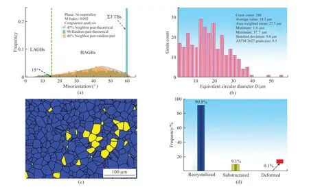
Fig.4 Distribution of misorientation and re-crystallization fraction ∆T=253 K: (a) Misorientation;(b) Grain diameter;(c) Re-crystallization area;(d) Re-crystallization fraction

Fig.5 Selected area electron diffraction (SAED) of Cu60Ni35Co5 alloy at ΔT=253 K
Firstly,the grain boundaries were relatively straight,and almost all grains exhibit regular hexagonal morphology.The second was that its grain orientation was random and there were no other high-strength textures.In Figs.4(c) and 4(d),blue color represents re-crystallization area,yellow color represents substructure area,and red color represents deformed grain.According to statistics,the re-crystallization fractionwas 90.8%,the substructure was only 9.1%,and the deformed grains were few.This indicated that the alloy structure experience relatively completed recrystallization at ∆T=253 K.The substructure was the result of the alloy structure recovery.
Liuet al[17]stress-induced re-crystallization mechanism was likely to explain the internal cause of refinement.He proposed that dendrites accumulate stress during rapid solidification,and the accumulated stress would gradually increase with the increase of under cooling.When the under cooling exceeds the critical value,the stress accumulated on the dendrite exceeds the strength limit of the alloy and collapses into dendrite fragments.The strain energy stored in these small fragments derived the alloy to re-crystallize.In order to verify the mechanism,the grain refinement structure was then examined by TEM to observe the internal conditions.Figs.6(a) and 6(b) show the microstructure contained a dense dislocation network.As shown in Figs.6(c) and 6(d),it was observed a large number of edge dislocations under the high-resolution microscope,which further demonstrated the high degree of plastic strain.It can be seen that the refined structure also contained a high density of dislocation defects,which was also consistent with the principle of plastic strain induced by stress accumulation as described above.This was the final result of the stress accumulation,eventually exceeding the yield strength of the alloy,which also provided a thermodynamic impetus for further refinement.All of above indicated that the alloy consumed most of the energy in the dislocation during the re-crystallization stage,thus forming a large number of low density dislocation areas.However,there were still many high density dislocation networks in some regions,which indicated that the alloy was re-crystallized after deformation.The energy of re-crystallization was from deformation energy.In addition,there were dislocations not only in the crystal but also at the grain boundary.
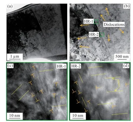
Fig.6 TEM characterization of refined structure of Cu60Ni35Co5 alloy ∆T=253 K
4 Laser cladding process
4.1 Principle of laser cladding
Laser cladding[23,24]is an advanced manufacturing process for surface modification of materials,which uses a high-energy-density laser beam to irradiate metal powders so that they melt and coat the surface of the substrate,which can improve the physical properties of the substrate surface.Laser cladding technology on 304 stainless steel surface treatment has a wide range of application prospects.Hanet al[25]melted Ni60 alloy powder on 304 stainless steel substrate by laser cladding technology.The results showed that the hardness,abrasion resistance and corrosion resistance of Ni60 coating with good cladding quality were greatly improved compared with that of the substrate.In the 304 steel surfaces by laser alloying the preparation of FeMnSi memory alloy layer was made by Jianget al[26],the results proved that the preparation of FeMnSi memory alloy significantly were improved the corrosion resistance in seawater environment.304 stainless steel[27]surface laser cladding was often used to choose high entropy alloy powder[28].Nickel-based alloy powder[29],cobalt-based alloy powder improved its corrosion resistance.Laser cladding of cobaltbased alloys on the 304 stainless steel surface made the surface with good corrosion-resistant coatings,which were valuable in the medical device field.
4.2 Corrosion performance analysis of laser cladding coatings
The size of the cladding substrate is 220 mm ×110 mm×10 mm 304 stainless steel.It is necessary to remove the surface oxide layer before the test to ensure that the surface of the cladding is smooth and clean,and finally wiped with 70% alcohol solution,then dries it with a hair dryer.The cladding material is Stellite12 alloy powder,which is spherical in shape with an average particle size of 45 μm,and the composition of the matrix and cladding material is shown in Table 1.

Table 1 Chemical compositions of substrate and cladding layer
Firstly,it is necessary to be grinded and polished with a grinder before laser cladding until a metallic luster appears.Secondly,the top and bottom of the substrate are parallel.Finally,the grinded substrate is cleaned with anhydrous ethanol and dried.After a number of experimental,laser with power 1.5 kW,(Ar) as the protective gas and powder feeding gas,the powder feeding speed is 1rad/min,the melting rate is 0.9m/min,the defocus distance is 25 mm,and the lap rate reaches 66.7%.The powder feeding tube and air outlet tube are fixed on the robot arm to prevent the robot arm from turning and blocking the powder.Table 2 shows the parameters of the laser melting Stellite12 coating equipment.

Table 2 Equipment parameters for laser cladding Stellite12 coating
The Stellite12 alloy specimens 15 mm×15 mm×10 mm after laser cladding.Field emission scanning electron microscopy (SEM) with energy dispersive spectroscopy (EDS) and optical microscopy (OM)were used,respectively.The corrosion morphology of the coatings and substrates as well as the elemental analysis and micro structural morphology of the specimens were observed and analyzed.The physical structure of the cladding layer was detected by X-ray diffractometry.The physical structure of the cladding layer was examined by X-ray diffraction (XRD) with a wavelength of 0.154060 nm,a scanning step of 0.01,and a scanning range of 20°-90°.
The polarization curves and AC impedance spectra of the samples were an electrochemical workstation (RST5000) in 3.5wt% NaCl solution.The specific parameters of one of the electrochemical experiments are shown below:
Working electrode with a surface area of 1 cm2,a saturated calomel electrode and a platinum metal sheet were used as reference and auxiliary electrodes for post-polishing impedance testing after establishing a stabilizing voltage.The frequency range was 100-103 Hz,the AC amplitude was 10 mV,and the potentiodynamic polarization test was carried out at a scanning rate of 0.2 mV/s during the period of -1.5-1.5 V.The test was carried out at a scanning rate of 0.2 mV/s during the period of 100-103 Hz.
4.3 Analysis and discussion of coating properties
As shown in Fig.7(a),the contour characteristics of the cladding layer were no defect after laser cladding;Fig.7(b) illustrates the surface roughness inspection,Ra=0.108 mm.The surface of the cladding layer and the overlap rate had an effect on the surface roughness.The penetration probing of the cladding surface is shown in Fig.7(c),which revealed that the cladding surface was free from defects such as cracks.

Fig.7 (a) The external characteristics of the cladding layer;(b) Surface accuracy of cladding layer;(c)Surface condition detection
The micro structural characterization of the cross section of the cladding layer is shown in Fig.8.The cladding layer was fused on the substrate without porosity defects cracks.Examination of the crosssection of the cladding layer by energy spectrometer showed the presence of multiple compositional variations in the transition region.This is a result of the strong interaction between the cladding and the substrate in the bonding zone.
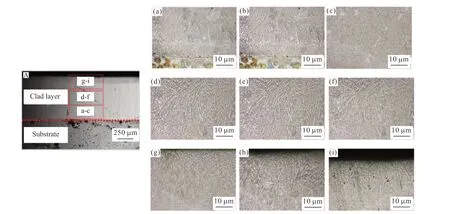
Fig.8 The microstructure morphologies of the cross-section of the cladding layer: (A) Morphology of clad layer;(a-c) Bottom microstructure;(d-f) Central microstructure;(g-i) Top microstructure
The microstructure of the upper cladding surface is shown in Fig.9.The crystals on the upper surface of the cladding layer are columnar,dendritic and planar.The growth of the organization of the upper surface on the cladding layer was not uniformly.Two points on the upper surface of the cladding layer (marked points in Fig.9,1 in the dendrites and 2 between the dendrites)were analyzed by energy spectroscopy,and the elemental content of EDS at the two points is shown in Table 3.The results show that the elemental contents of the two points are quite different.Point 1 is the primary phase of Co,which is a solid solution containing a large number of other elements.Point 2 has more C,Cr,and W elements than point 1,and there is a eutectic organization at the position of point 2,which contains Co and carbides (eg,CrxCy,W2C).

Table 3 EDS element content of A

Fig.9 Surface microstructure morphologies of the cladding layer: (a)Microstructure of coating surface;(b) Partial enlarged figure A
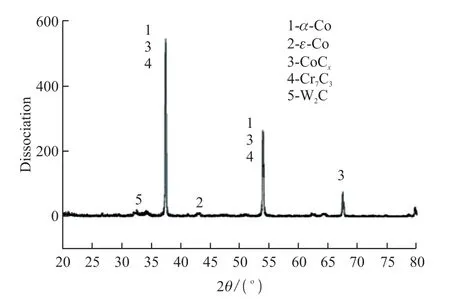
Fig.10 X-ray diffraction pattern of cladding layer
4.4 Electrochemical corrosion and its mechanism
From Fig.11,it can be seen that the opencircuit potentials of the cladding and the substrate were relatively stable,which minimized interference during electrochemical testing.Fig.11(a)+shows the polarization curves of the cladding and substrate.The fitting results of the polarization curves on the substrate and the cladding are shown in Table 4,it can be seen that the self-corrosion potentials on the cladding.The substrates were -503.5 and -577.8 mV.The electrochemical workstation test system validated by simulation results showed that the corrosion resistance of the cladding layer was much higher than the substrate.As shown in Table 4,the cladding layer has a higher passivation potential and pitting potential,which indicates that it has a better corrosion resistance performance.Fig.11(b) shows the Nyquist diagram,Fig.11(c) shows the Porter diagram,it can be seen that the curvature radius of cladding layer was larger than the base material curvature.The cladding layer impedance modulus was much larger than the base material.It was shown that the impedance of the cladding layer was larger and the corrosion resistance is better.

Fig.11 EIS figures of cladding layer and substrate in 3.5% NaCl: (a) Polarization curves;(b) Nyquist plot;(c) Bode plot
As shown in Fig.12,the microscopic morphology of the electrochemical corrosion of the fusion cladding and the substrate.In Fig.12(a) and Fig.13(a),the electrochemical corrosion of the coating,it produced a slight uniform pitting,accompanied by slight corrosion cracks.After electrochemical corrosion of the substrate surface,it appeared serious corrosion,not uniform.Only a small amount of the substrate surface was not corroded,as shown in Fig.12(b) and Fig.13(b).In Fig.13(b),It can be seen that the reduction potential of a large number of Fe elements in the 304 stainless steel matrix was much lower than the content of Co elements in Co-based alloy coatings.With the Cr element,the alloys were a certain protective,which improved its corrosion resistance.

Fig.12 Macro morphologies of electrochemical corrosion between coating and substrate: (a) Coating;(b) Substrate

Fig.13 Microscopic morphologies of electrochemical corrosion between coatings and substrates: (a) Coating;(b) Substrate
5 Conclusions
In this paper,Cu60Ni35Co5 alloy and its rapidly solidifying structure were obtained by the fluxing method.It was observed the transformation process of the alloy microstructure.The grain refinement mechanism of the highly undercooled structure was confirmed.The main conclusions are shown as follows:
a) The microstructure transformation of the alloy were through the process of “coarse dendrite -equiaxed crystal -oriented fine dendrite -equiaxed crystal”,and the whole process had twice grain refinement.
b) The grain orientation in the high under cooling structure was random,and there was a high proportion of HAGBs and TBs.The re-crystallization leaded to structural refinement,which was driven by the residual strain energy in the fractured dendrites.
c)It was found that the microstructure of the crosssection illustrated columnar crystals,planar crystals of smaller sizes,and the growth direction is disordered.
d) By electrochemical corroding,it was found that the cobalt and chromium elements in the coating were more likely to form dense films,which would improve its corrosion resistance.
Conflict of interest
All authors declare that there are no competing interests.
杂志排行
Journal of Wuhan University of Technology(Materials Science Edition)的其它文章
- Biotin-modified Galactosylated Chitosan-gene Carrier in Hepatoma Cells Targeting Delivery
- Mussel-inspired Methacrylic Gelatin-dopamine/Ag Nanoparticles/Graphene Oxide Hydrogels with Improved Adhesive and Antibacterial Properties for Applications as Wound Dressings
- Effect of Polyvinyl Alcohol in Inner Aqueous Phase on Stability of Millimeter-scale Capsules
- Synthesis and Characterization of Nonionic Waterborne Polyurethane and Application to Wool Fabric Finishing
- Fluorescent Double Network Hydrogels with Ionic Responsiveness and High Mechanical Properties for Visual Detection
- Damage Mechanism of Ultra-thin Asphalt Overlay (UTAO)based on Discrete Element Method
