Constitutive modelling of concrete material subjected to low-velocity projectile impact: insights into damage mechanism and target resistance
2024-02-05ShenLIUXiepingHUANGXiangzhenKONGQinFANG
Shen LIU, Xieping HUANG, Xiangzhen KONG, Qin FANG
Research Article
Constitutive modelling of concrete material subjected to low-velocity projectile impact: insights into damage mechanism and target resistance

1Center for Hypergravity Experiment and Interdisciplinary Research, Zhejiang University, Hangzhou 310058, China2Institute of Geotechnical Engineering, Zhejiang University, Hangzhou 310058, China3State Key Laboratory of Disaster Prevention & Mitigation of Explosion & Impact, Army Engineering University of PLA, Nanjing 210007, China
This paper presents a numerical study to improve the understanding of the complex subject of penetration and perforation of concrete targets impacted by low-velocity projectiles. The main focus is on the damage mechanisms and the major factors that account for the target resistance of the concrete. An improved continuous surface cap model recently proposed was employed. The model was first equipped with element erosion criteria and was adequately validated by comparisons with ballistic experiments. Comprehensive numerical simulations were carried out where the individual influence of tensile, shear, and volumetric behaviors (pore collapse) of a concrete target on its ballistic performance was investigated. Results demonstrated that cratering on the front face and scabbing on the rear face of the concrete target were mainly dominated by its tensile behavior. The major target resistance came from the second tunneling stage which was primarily governed by the shear and volumetric behaviors of the concrete. Particularly, this study captured the pore collapse-induced damage phenomenon during the high-pressure tunneling stage, which has been extensively reported in experiments but has usually been neglected in previous numerical investigations.
Penetration; Perforation; Damage mechanism; Target resistance; Projectile impact; Pore collapse
1 Introduction
Concrete is a frequently used material in military and civil engineering that may undergo impact and blast loads. Failure modes of concrete structures under these dynamic loads and the underlying damage mechanisms are thus of great interest and have attracted intensive attention for many years. For impact loads such as the penetration into concrete, numerous investigations (Rajput et al., 2018; Goswami et al., 2019; Liu et al., 2021; Xu et al., 2021) have been carried out during the last decades to enhance the understanding of this complicated problem. This study focuses mainly on the penetration problem with a numerical study performed to investigate the ballistic performance of concrete targets impacted by low-velocity projectiles.
It is well acknowledged that the penetration into concrete comprises, in general, two relevant problems (Hanchak et al., 1992; Yankelevsky, 1997). The first problem is penetration into a relatively thin target where the target can be perforated by the projectile with a residual velocity; the second problem is penetration into a sufficiently thick target where the projectile will be stopped within the target with a penetration depth considerably smaller than the target thickness such that no rear face effects can be observed. The two related problems have much in common but they are significantly different as well. In this study, both the problems will be considered. To make it easy to follow, we will refer to the first problem as perforation and the second problem as penetration.
In studies on the penetration and perforation problems (Hanchak et al., 1992; Yankelevsky, 1997; Huang et al., 2005; Leppänen, 2006; Wang et al., 2007; Forquin et al., 2008, 2015; Kong et al., 2016), typical failure modes of a concrete target can be commonly observed. Fig. 1 schematically illustrates the failure modes of a concrete target under perforation. In general, the whole perforation process can be divided into three stages. The first stage is associated with the entrance phase of the projectile, where cratering on the front face of the target can be observed. The second stage refers to the tunneling region, where a tunnel in the center with a size approximate to the projectile diameter will be created. The third stage is related to the exit phase of the projectile, where scabbing on the rear face is visible. For the penetration case, the third stage is generally absent and for some perforation cases with very thin targets, only the first and the third stages can be found and, the second tunneling stage is not present.
Fig. 1 Typical three-stage failure modes of a concrete target under perforation
The first point for discussion in this study is the damage mechanism behind the failure mode of the target during each stage. Discussions related to this topic are abundant (Hanchak et al., 1992; Yankelevsky, 1997; Huang et al., 2005; Leppänen, 2006; Wang et al., 2007; Chen et al., 2008; Forquin et al., 2008, 2015; Li et al., 2013; Kong et al., 2016; Xing et al., 2020); however, the opinions are quite controversial. In general, the second, tunneling, stage is well acknowledged to be associated with shear strength–pressure relations, since a triaxial compression stress state with high confining pressure is observed in the tunnel (Yankelevsky, 1997; Forquin et al., 2008, 2015). However, opinions concerning the controlled damage mechanisms in the first and the third stages are divided. On the one hand, Hanchak et al. (1992) pointed out that both the cratering and scabbing were produced by tensile spallation. Kong et al. (2016) also suggested that both the cratering and scabbing were tension-dominated phenomena. On the other hand, Wang et al. (2007) believed that the impacted area on the front face was primarily under compression and may fail due to high pressure, with the cratering on the front face resulting from the severe 'crushing-stress' together with a partially reflected tensile stress wave. Forquin et al. (2015) also concluded from their experimental results and numerical simulations that the cratering was mainly related to the 'confined behavior' rather than the tensile behavior of the target. Moreover, studies (Hanchak et al., 1992; Huang et al., 2005; Leppänen, 2006; Wang et al., 2007; Forquin et al., 2015; Kong et al., 2016) indicated that the scabbing on the rear face was dominated by the reflected tensile stress wave. In addition, researchers (Chen et al., 2008; Li et al., 2013; Xing et al., 2020) believed that both the shear plugging and tensile spallation appeared almost at the same time on the rear face of the target and that shear failure rather than tensile failure was dominant.
Based on the literature review presented, the damage mechanisms are arguable and further efforts are required. Also, at least two aspects should be considered. Firstly, the damage mechanism that controls the formation of the cratering and the scabbing is not clear. To approach this issue, ballistic experiments or numerical simulations with well-designed concrete targets are needed. The targets in a control group should have different mechanical behaviors in a certain aspect and identical behaviors in the other aspects, so that the individual influence of the different mechanical behaviors of the target during different stages can be acquired. Secondly, although a triaxial compression stress state with high confining pressure is well acknowledged in the tunneling region, understanding of the damage mechanism during this stage is still inadequate. For instance, the damage mechanism due to pore collapse under high pressure is commonly neglected in most of the existing numerical studies. However, Holmquist et al. (1993) pointed out that pore collapse under high pressure will cause a great loss of cohesive strength of materials. This phenomenon has also been mentioned in (Forquin et al., 2008). In addition, more recently, the experimental results from Cui et al. (2017) indicate that over 50% of the material strength and modulus have been lost after the material has suffered a hydrostatic loading test with the pressure up to 500 MPa. Considering the high confining pressure observed during the second tunneling stage, damage due to pore collapse will be very severe there and must be considered in the numerical simulations.
Besides the damage mechanisms, opinions upon the major factor that accounts for the target resistance are also rather controversial and in some cases conflict with the views on the damage mechanisms behind the failure modes of the concrete target. For instance, although many researchers (Leppänen, 2006; Kong et al., 2016) believed that the cratering and the scabbing were tension-dominated phenomena, they still suggested that the target resistance was mainly determined by the compressive behavior and the strain-rate-dependent responses of the concrete in compression; the contribution of the tensile behavior was neglected. However, these conclusions were questioned by Forquin et al. (2015) through a set of ballistic experiments and numerical simulations. Forquin et al. (2015) concluded from their results that tensile behavior can strongly influence the concrete target resistance. Beppu et al. (2008) also pointed out that tensile behavior was important.
There have also been many attempts made to propose analytical models (Durban and Masri, 2004; Masri and Durban, 2005; Rosenberg and Dekel, 2010; Rosenberg and Kositski, 2016; Kong et al., 2017a, 2017b) and empirical formulae (Forrestal et al., 1994, 1996) to predict the target resistance. More details are in the reviews (Li et al., 2005; Yankelevsky, 2017). These attempts can be covered generally by two kinds of models. The first kind of models are those where the unconfined compressive strength of the target appeared to be the major factor of the target resistance (Rosenberg and Dekel, 2010; Rosenberg and Kositski, 2016). In those models, the predicted penetration depth of the projectile was inversely proportional to the square root of the unconfined compressive strength. However, experimental observations (Hanchak et al., 1992) have shown that an increase in the unconfined compressive strength of a factor of three had a very limited influence on the target resistance for impacting velocities ranging between 300 and 1100 m/s. Experimental studies (Yankelevsky, 2017) have also revealed that concrete targets of similar unconfined compressive strength demonstrated different ballistic resistances depending on their different concrete compositions. These findings indicated that unconfined compressive strength was insufficient to be the major factor of the target resistance. Researchers (Forquin et al., 2008, 2015; Kong et al., 2017a, 2017b) also argued that unconfined compressive strength was not the major factor. These debates led to another kind of analytical model: the dynamic cavity model (Durban and Masri, 2004; Masri and Durban, 2005; Kong et al., 2017a, 2017b). In the dynamic cavity model, much more complicated mechanical behaviors of the target were required to describe the target resistance, including deviatoric behaviors (shear strength–pressure relations) and volumetric behaviors (volumetric strain–pressure relations).
In light of the literature review, more efforts are still required to understand the major factor that accounts for the target resistance and that is the second point that the current study will discuss. More attention should be focused on at least two aspects related to the target resistance. Firstly, whether the unconfined compressive strength is sufficient or the complex shear and volumetric behaviors considered in the analytical models are necessary, should be further discussed. Secondly, although tensile behaviors can strongly influence the formation of the cratering and the scabbing, the influence of tensile behaviors on target resistance has been commonly neglected and needs to be further investigated.
This study aims at enhancing the understanding of these two points especially in the detailed four aspects discussed above. It must be pointed out that to explore these issues experimentally needs well-designed concrete targets and a high number of experiments to improve the statistics; these are not easy and are generally expensive. Numerical simulation naturally has advantages in dealing with these issues thanks to the rapid development of computational power, numerical methods, and constitutive models. As for the constitutive models for studying the complex penetration and perforation problems, the physical mechanisms of the concrete due to microcracks and pores as well as their combinations should be considered. In this study, the concrete model recently proposed by Huang et al. (2021) is adopted with minor modifications. This model can well capture the mechanical behaviors of rock and concrete materials under complex stress states. In particular, three damage mechanisms are considered: hydrostatic damage due to pore collapse under high pressure, shear damage due to shear-induced microcracking, and tensile damage due to tensile microcracking. This model will first be equipped with element erosion criteria and then sufficiently validated by comparisons with ballistic experiments before the numerical study.
It should be mentioned that this study focuses on the ballistic performances of conventional concrete materials. Fiber-reinforced concrete and ultrahigh-performance concrete are not included. In addition, a plastic-damage constitutive model within the framework of the finite element method is employed to predict the different damage phenomena (tensile, shear, and volumetric) during the projectile's impact on the concrete material. The finite element method, incorporating a well-developed constitutive material model, has been frequently used in predicting the damage and failure of concrete materials subjected to impact and blast loadings. However, there are also many other numerical methods, such as the discrete cohesive zone model (Feng et al., 2018; de Maio et al., 2022) or the phase field method (Nguyen et al., 2022), that have been proposed and show good performances in capturing crack patterns and failure modes in concrete materials. These numerical methods provide good alternatives and can also be considered in the future.
The remainder of this paper is structured as follows: in Section 2, a brief description of Huang et al. (2021)'s concrete model will be presented; in Section 3, Huang et al. (2021)'s concrete model will be fully validated with inclusion of parameter calibrations, element erosion criterion effects, mesh size effects, and comparisons with ballistic experiments; in Section 4, a numerical study will be presented where the individual influence of the tensile, volumetric, and shear behaviors of the target on ballistic performance will be investigated; in Section 5, there is a discussion upon the two main points especially in respect of the detailed four aspects mentioned above, and some conclusions are drawn.
2 Constitutive model
A brief introduction to Huang et al. (2021)'s concrete model is presented in this section, including the plastic model and damage model. With minor modifications, this concrete model will be adopted for the numerical study.
2.1 Plastic model
In Huang et al. (2021)'s concrete model, a three-invariant yield functionis used to trigger the initiation of plasticity, which is formulated as:

In Huang et al. (2021)'s concrete model, the fracture functionfis defined as
wheredenotes the hydrostatic pressure.cis the unconfined compressive strength andis the unconfined tensile strength.1and2are strength parameters which should be calibrated through the triaxial compression test data.represents the ratio of tensile meridian to compressive meridian, which is related to. The piecewise functionfor concrete materials suggested in (Nguyen et al., 2022) is adopted in this study, which reads as:
Note that linear interpolation will be used to determine the value ofunder different pressure levels when coding the material models.
The cap functioncis non-dimensional, and ranges between zero and unity. In Huang et al. (2021)'s concrete model,cis defined as
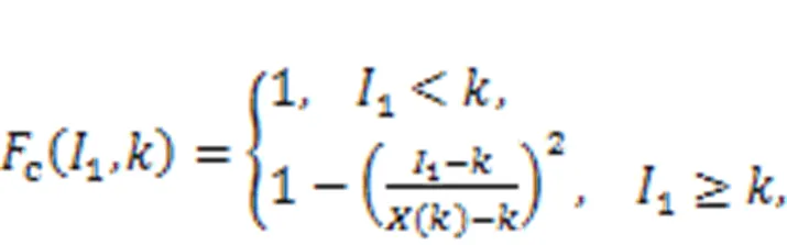
where1is the first invariant of the stress tensor andis an internal variable.() is a function of the internal variable, which is formulated as:
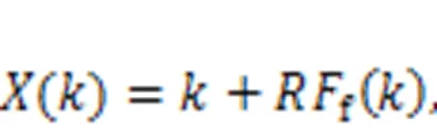
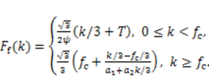
whereis a material constant. The relationship between() andgiven in Eq. (5) determines the shape of the cap function. The functionf() in Eq. (5) is determined by substituting the pressurein Eq. (2) with one-third of the internal variable, which is then formulated as:
The ratio of the current meridian to the compressive meridian′ is defined as

wheredenotes the Lode-angle.
Numerous investigations (Rossi, 1991) have revealed that under high strain-rate conditions, concrete material has much higher strength than that under quasi-static loadings. One cause of the strain-rate effect is associated with the free water in the capillary pores of the concrete. Due to the presence of free water, opposed viscous forces will be generated to delay or prevent the propagation of the microcracks and, at the macroscopic level, the material strength and stiffness increase (Huang et al., 2020). To account for the strain-rate effect, the radial enhancement approach is adopted, with the failure functionenhanced as:
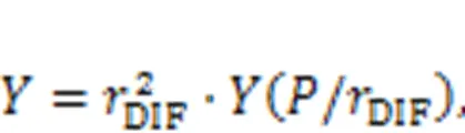
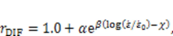
whereDIFrepresents the ratio of dynamic strength to static strength and DIF is the dynamic increase factor.
As for the relationship betweenDIFand strain rate, Huang et al. (2020) have proposed a concise semi-empirical formula with three material parameters:
In addition, one may find that the defined plastic model is mainly dependent on the compressive strengthcof the concrete material. In this way, the performance of the proposed model in predicting the mechanical behaviors in compression is highly dependent onc. Thus,cof the concrete material should be well calibrated.
2.2 Damage model
The major contribution of Huang et al. (2021)'s concrete model is the establishment of three damage mechanisms of rock-like materials, which are hydrostatic damage due to pore collapse, shear damage due to shear-induced microcracking, and tensile damage due to tensile microcracking. In this section, the three damage mechanisms will be briefly introduced.
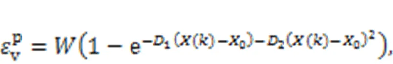
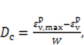
Hydrostatic damage is proposed to account for the degradation of material properties due to pore collapse. This has been neglected in most of the other existing material models. The hydrostatic damage for concrete materials can be attributed to two factors. Firstly, concrete is typically a heterogeneous material. Unlike in some homogeneous materials, such as metals, stress concentrations and strain localizations will occur in concrete even under purely hydrostatic loading. As a result, the material can be damaged. Secondly, concrete is a porous material. Pores will be collapsed under high pressure, accompanied by a great loss of cohesive strength—as pointed out in (Holmquist et al., 1993; Cui et al., 2017). Considering these two aspects, the hydrostatic damage in Huang et al. (2021)'s concrete model is formulated based on the irreversible plastic volumetric strain (plastic compaction). In a cap model, the following isotropic hardening rule is commonly used to update the internal variableand to calculate the irreversible plastic volumetric strain:
As opposed to plastic compaction due to pore collapse, the shear will cause plastic dilatation to overcome the incompatibilities on the microcrack surfaces. In Huang et al. (2021)'s concrete model, the shear damage is formulated based on the growth of the plastic dilatation. To formulate the shear damage, a modified equivalent plastic volumetric strainis proposed as a function of the plastic dilatation, and is represented by:
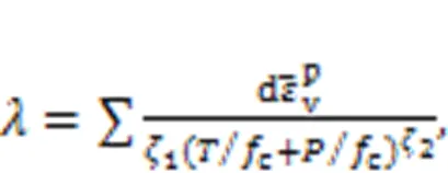
To describe the tensile behavior of concrete, the TCK continuum damage model (Taylor et al., 1986) has been completely incorporated into Huang et al. (2021)'s concrete model. In the TCK model, the tensile damage is formulated based on the crack densityd, which is formulated based on the current pressure level and defined as


A core task in establishing different damage mechanisms is to identify their borders so that the established damage mechanisms will not intersect each other. In the present study, three damage mechanisms are considered, with the first two (hydrostatic damage and shear damage) related to stress states in compression, and the third one (tensile damage) associated with stress states in tension. In the computational codes, pressure is used to distinguish the stress states with>0 for compression and<0 for tension. Hence, the tensile damage can be easily distinguished, which will not intersect those in compression. Further, as discussed above, the hydrostatic damage and shear damage are generated by different physical mechanisms and accumulated exclusively with the corresponding plastic deformation, and hence they will not intersect each other. In this way, the three damage mechanisms are mutually independent and will not intersect each other.
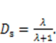
In this study, the way the damage index degrades the stress tensor is different from that in the original Huang et al. (2021)'s concrete model. A total damagetotis proposed based on the hydrostatic damagec, shear damages, and tensile damaget, and is formulated as:
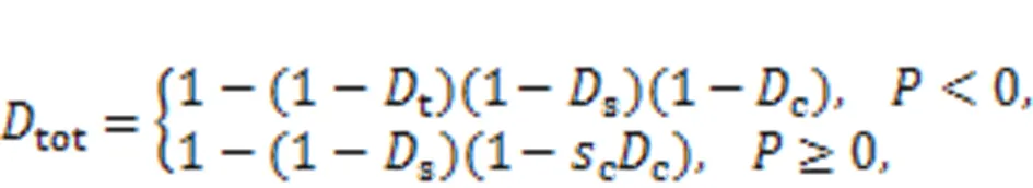
wherecis a material parameter.tothas different forms for tension with pressure<0 and for compression with pressure≥0. For tension, previous study (Batzle et al., 1980) has shown that previous damage in compression will weaken the subsequent tensile behavior. Therefore, through the definitions oftotin Eq. (16),tis 'strengthened' bysandc. For instance, imagine that the concrete experiences compressive loadings firstly withs=0.5 andc=0 orc=0.5 ands=0, and then after that the concrete suffers from tensile loadings witht=0.5. The total damagetotbased on Eq. (16) will be 0.75, which is higher thant=0.5 and thus can yield weaker tensile behavior. For compression,tis absent which means that the previous tensile damage will not affect the subsequent compressive behavior. It is mainly due to the microcrack closure effect (Batzle et al., 1980; Zhu and Arson, 2014), which is represented by the tensile microcracks that can be reclosed upon load reversal; consequently, the degraded compressive strength and modulus can be recovered. On the other hand, hydrostatic damage can influence the compressive behaviors. In addition, based on the experiments (Cui et al., 2017) and our previous study (Huang et al., 2021), it is found that the influence of hydrostatic damage is more severe on the tensile behavior compared with the compressive one. This accounts for the existence of the material parametercin Eq. (16) for compression. Based on experiments (Cui et al., 2017) and our previous study (Huang et al., 2021),c=0.6 is suggested and will be used in this study.
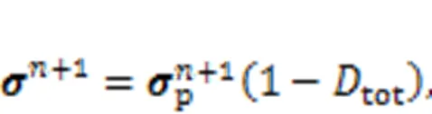
Finally, the stress tensor will be degraded by the total damage through:
3 Comparison with ballistic experiments
A set of well-designed penetration and perforation experiments into plain concrete slabs with the projectile data recorded was presented in (Forquin et al., 2015). Damage profiles of the concrete targets were also given based on topographic analysis. In this study, a numerical study based on these ballistic experiments will be carried out. Before the numerical study, the adopted Huang et al. (2021)'s concrete model will be sufficiently validated in this section by comparisons with the experimental results in (Forquin et al., 2015). Approaches to calibrate the required parameters are given. Element erosion criteria are introduced into Huang et al. (2021)'s concrete model. Influences of the element erosion criterion and mesh size of the concrete target are presented.
3.1 Parameter calibration
There are in total 17 material parameters required in Huang et al. (2021)'s concrete model. These parameters can be classified into four categories. Approaches for determining these parameters will be discussed here.
The first category contains the common material parameters including the mass density, Young's modulus, Poisson's ratio, compressive strengthc, and tensile strength. These parameters can be obtained relatively easily. Table 1 summarizes these parameters that will be used in the numerical simulations.andare acquired from the experiments in (Forquin et al., 2015), whilecandare empirically determined in (Kong et al., 2018) based on Young's modulus. A commonly used value of, i.e., 0.2, is adopted for the concrete.
The second category contains the shear behavior related parameters, including strength parameters1and2in the fracture function, and shear damage evolution parameters1and2.1and2should be determined by matching with the triaxial compression test data. A set of triaxial compression test data for concrete (Xie et al., 1996; Hou, 2006; Xiong, 2009) with similar material properties to that used in the ballistic experiments of Forquin et al. (2015) has been collected, as shown in Fig. 2a. With these test data,1and2have been calibrated to be1=0.5876 and2=0.025/c.1and2can be determined by the softening portion of the strain–stress curves in an unconfined uniaxial compression test. The suggested values for1and2are 0.02 and 1.5, respectively.
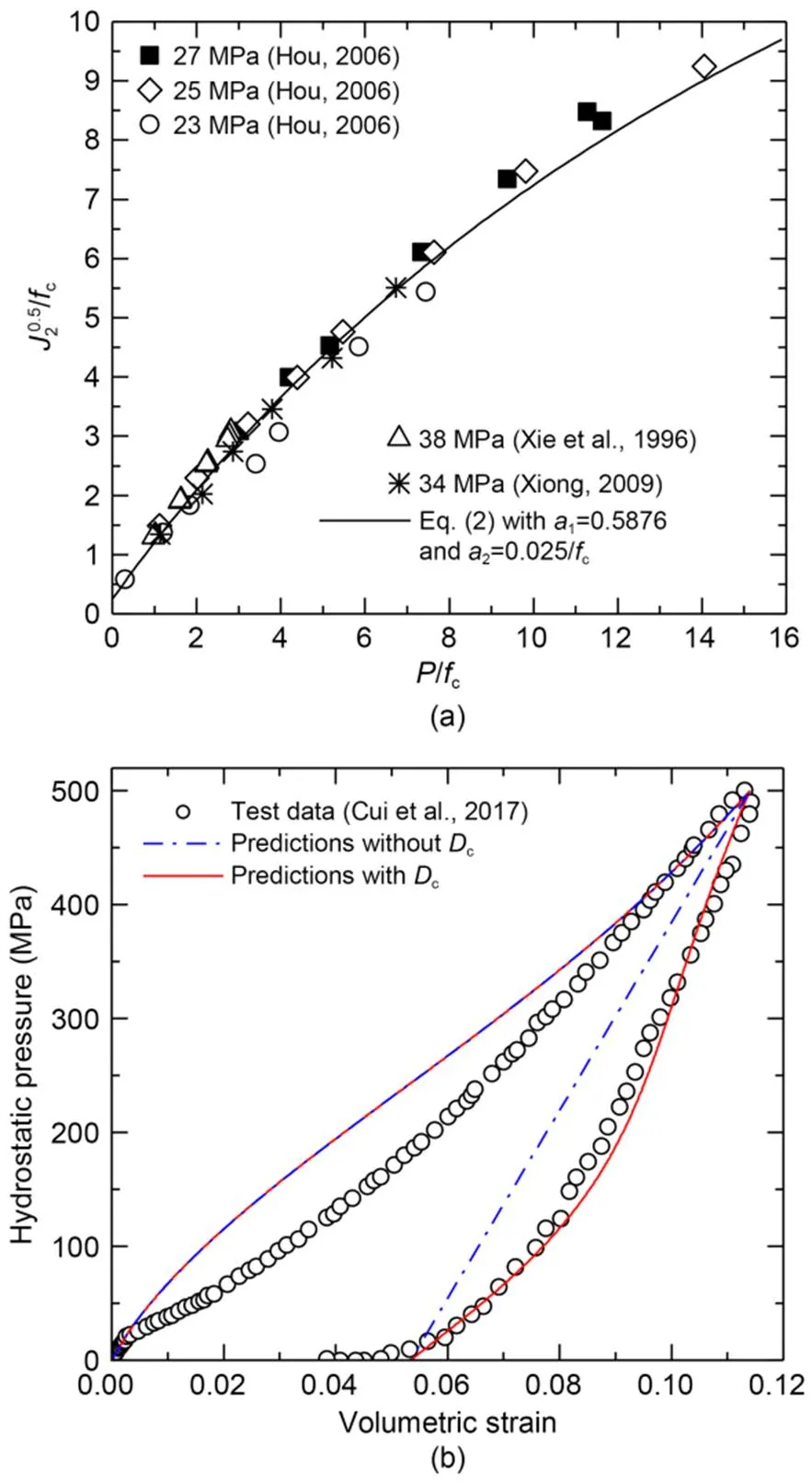
Fig. 2 Behaviors of concrete under high confining pressure and fitting curves for Huang et al. (2021)'s model: (a) shear behaviors; (b) volumetric behaviors
The third category contains the volumetric behavior related parameters, including the hardening parameters,,0,1, and2. These parameters should be determined by the hydrostatic compression test data. A set of hydrostatic data for concrete is available in (Forquin et al., 2015); however, it lacks the unloading stage that is important to demonstrate the hydrostatic damage mechanism proposed in Huang et al. (2021)'s concrete model. In view of this, the volumetric strain–pressure curve for concrete with the unloading process from experiments (Cui et al., 2017) is adopted to calibrate these parameters. By matching with the test data, the hardening parameters are calibrated with=0.06,=6,0=102 MPa,1=1.22×10⁻¹⁰Pa-1, and2=1.00×10⁻¹⁸Pa-2. The predicted volumetric strain–pressure curves by Huang et al. (2021)'s concrete model, with and without consideration ofc, together with test data (Cui et al., 2017) are depicted in Fig. 2b. Differences exist in the unloading process. By inspection of Fig. 2b, one may find that predictions withccan reflect the bulk modulus degradations during the unloading process, and are very consistent with the test data. However, predictions withoutcare linear and parallel to the initial loading stage with no degradations of the bulk modulus, which is inconsistent with the test data. This phenomenon demonstrates the need to consider the hydrostatic damage due to pore collapse.
The fourth category contains the tensile behavior related parameters, including material constantstand, and the fracture toughnessIC. Approaches to determine these parameters have been fully discussed in the TCK model (Taylor et al., 1986). The widely used parameters for concrete, as suggested in (Huang et al., 2005; Wang et al., 2007), are adopted here, witht=5.753×10²¹m-3,=6, andIC=2.74×10⁶Pa·m0.5.
All the determined or suggested parameters for Huang et al. (2021)'s concrete model are summarized in Table 1 and will be used in this study.

Table 1 Material parameters of the current model for concrete
3.2 Numerical model
In the penetration and perforation experiments presented in (Forquin et al., 2015), a steel projectile with filler was launched into a cylindrical unreinforced concrete target. The ogive-nosed steel projectile was 52 mm in diameter and 300 mm in length, with a mass of 2.4 kg. For the penetration case, the concrete target was 800 mm in thickness and was impacted by the projectile with an initial velocity of 347 m/s. For the perforation case, the concrete target was 300 mm in thickness and was impacted by the projectile with an initial velocity of 333 m/s. In both cases, the concrete targets were 800 mm in diameter. The cylindrical concrete targets were surrounded by steel rings to constrain the radial displacement. In the present study, both the penetration and perforation cases are simulated. Fig. 3 presents the numerical models. Considering the symmetry of the experiments, only 1/4 of the concrete target, the steel projectile, and the steel rings are simulated to save the computational time. Symmetric boundary conditions are applied on the symmetric planes. The steel projectile and the steel rings are taken as rigid bodies. The penalty method available in LS-DYNA is implemented here to define the contact behaviors. Specifically, the keyword 'contact erosion surface to surface', is employed to describe the interaction between the concrete target and the steel projectile, as well as between the concrete target and the steel rings.
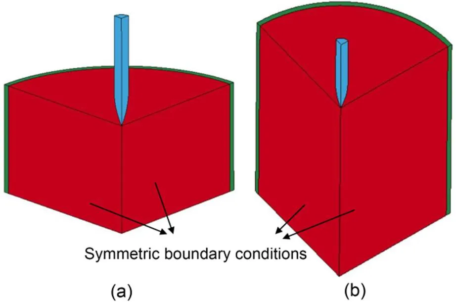
Fig. 3 Numerical models of the ballistic experiments: (a) 300 mm thin concrete target perforated by a projectile at 333 m/s; (b) 800 mm thick concrete target penetrated by a projectile at 347 m/s
3.3 Influence of friction, element erosion, and mesh size
3.3.1Frictional effect
Studies (Forquin et al., 2015; Zhao and Wen, 2018) have pointed out that friction should be considered when conducting impacting simulations. The frictional effect can be introduced easily through the contact algorithm available in LS-DYNA. The equation to describe the friction is formulated as:
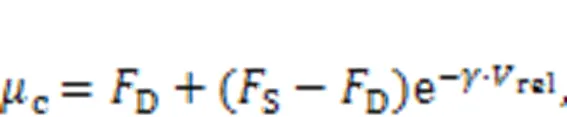
wherecis the coefficient of friction.Dis the dynamic coefficient of friction andSis the static coefficient of friction.relis the relative velocity of the surface in contact andis the exponential decay coefficient. The values of these coefficients based on research (Forquin et al., 2015; Zhao and Wen, 2018) are used, i.e.,D=0.05,S=0.5, and=0.07.
3.3.2Element erosion criterion
Within the finite element method, the element erosion criterion is critical and is used not only to trigger the initiation and growth of cracks but also to delete the distorted elements. Otherwise, the failure of concrete structures subjected to dynamic loadings always involves large strain which results in the mesh entanglement and distortion that can prematurely terminate the numerical analysis. In the original Huang et al. (2021)'s concrete model, the element erosion criterion was absent since no numerical simulations at a structural level were involved. In this study, the element erosion criterion will be introduced into Huang et al. (2021)'s concrete model as follows.

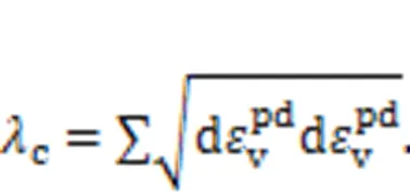

Fig. 4 Influence of element erosion criterion on the projectile velocity–time histories for a 300 mm concrete target perforated by a steel projectile at 333 m/s
3.3.3Mesh size effect
The influence of mesh size for the concrete target is evaluated. The predicted projectile velocity–time histories for the perforation case with mesh sizes of 2.5, 4.0, and 6.0 mm are presented in Fig. 5. Very similar results are obtained for the three mesh sizes and, with the increase of the mesh size, the residual velocity of the projectile decreases slightly. For a sake of balance between efficiency and accuracy, a mesh size of 4.0 mm for the concrete target will be used.
Fig. 5 Influence of the mesh size for the concrete target on the projectile velocity–time histories for a 300 mm concrete target perforated by a steel projectile at 333 m/s
3.4 Comparison and validation
With the parameters summarized in Table 1, the numerical models illustrated in Fig. 3, the element erosion criterion discussed in Section 3.3.2, and the mesh size of 4.0 mm for the concrete target determined in Section 3.3.3, numerical simulations for both the perforation and penetration cases are carried out. Figs. 6 and 7 present comparisons between numerical predictions and experimental results for failures in concrete targets after impacts for the perforation and penetration cases, respectively. For the perforation case with a 300 mm thin concrete target impacted by a projectile at 333 m/s, as shown in Fig. 6, the three typical failure modes can be clearly observed, i.e., cratering on the front face, tunneling in the center, and scabbing on the rear face. The numerically predicted failure patterns shown in Fig. 6b are reasonably consistent with those obtained experimentally and illustrated in Fig. 6c. For the penetration case with an 800 mm thick concrete target impacted by a projectile at 347 m/s, as shown in Fig. 7, the scabbing on the rear face is absent since the projectile will not perforate the concrete target. However, the cratering on the front face and the tunneling region can still be clearly seen. Again, the failure patterns obtained numerically and experimentally, shown in Figs. 7b and 7c respectively, agree well.

Fig. 6 Comparisons between numerical predictions and experimental results for the concrete targets after impacts for the perforation case: (a) numerically predicted damage profiles (section view); (b) numerically predicted failure patterns (section view); (c) experimentally obtained failure patterns (topographic analysis). References to color refer to the online version of this figure
Fig. 7 Comparisons between numerical predictions and experimental results for the concrete targets after impacts for the penetration case: (a) numerically predicted damage profiles (section view); (b) numerically predicted failure patterns (section view); (c) experimentally obtained failure patterns (topographic analysis). References to color refer to the online version of this figure
Comparisons between numerical predictions and experimental data for the projectile data for both the perforation and penetration cases are presented in Fig. 8. One may find that the numerically predicted projectile data including the acceleration–time histories, the velocity–time histories, and the penetration depth–time histories are very consistent with the corresponding experimental data. Furthermore, by inspection of Figs. 6 and 8a for the perforation case, there are three obvious stages in the projectile acceleration–time histories, which correspond to the three failure modes shown in Fig. 6:
(1) The first stage (entrance phase). This stage is from the start to 300 μs.In this stage, the projectile acceleration increases linearly. This stage generally corresponds to the entrance phase of the projectile; the typical failure mode, i.e., cratering on the front face of the concrete target, belongs to this stage.
(2) The second stage (tunneling in the center). This stage is from 300 to 750 μs. In this stage, it is observed that the projectile acceleration is almost constant. Tunneling in the center of the concrete target belongs to this stage and the size of the tunnel is approximately the projectile diameter.
(3) The third stage (exit phase). After 750 μs comes the third stage. In this stage, the projectile acceleration decreases almost linearly. This stage is generally accompanied by the exit phase of the projectile; the typical failure mode, i.e., scabbing on the rear face of the concrete target, belongs to this stage.
Very similar results can be observed for the penetration case except for the absence of the third stage (exit phase). As shown in Fig. 8c, there are two stages in the acceleration–time histories of the projectile. The first stage corresponds to the entrance phase of the projectile, from the start to 300 μs, and the acceleration of the projectile increases linearly. Cratering on the front face of the concrete target can also be observed in this stage, as shown in Fig. 7. After 300 μs comes the second stage (around 300–1300 μs). Again, in this stage, the projectile acceleration is almost constant. Tunneling with size approximate to the projectile diameter can be observed.
Fig. 8 Comparisons of projectile data between numerical predictions and experimental data: projectile acceleration–time histories (a) and projectile velocity–time histories (b) for the perforation case; projectile acceleration–time histories (c) and penetration depth–time histories (d) for the penetration case
4 Numerical study
The good performance of Huang et al. (2021)'s concrete model demonstrated in the ballistic simulations above is the solid foundation of the numerical study performed in this section. The major two points and especially the detailed four aspects discussed previously will be investigated. The numerical study is arranged by changing the mechanical behaviors of the target in one aspect while those in the other aspects remain unchanged. In this way, the individual influence of the tensile, volumetric, and shear behaviors of the target on its ballistic performance can be accessed. Some interesting findings are obtained.
4.1 Influence of tensile behavior
In Huang et al. (2021)'s concrete model, the tensile behavior is completely described by the TCK model. Tensile behaviors including the strain-rate effect and the tensile damage evolution are governed by parameterst,, andIC. Changing some of them, the concrete will show different tensile behaviors no matter which of them is changed. To investigate the influence of the tensile behavior, five different tensile parameter schemes are arranged, as listed in Table 2. In the arrangement, parametersandICare maintained, withtranging between 5.753×10¹⁹and 5.753×10²³(one may also choose to change one of the other parameters and maintain the other two). A largertyields weaker tensile behaviors represented by lower tensile strengths and higher damage growth rates. Considering this, the five tensile parameter schemes in Table 2 are marked with 'Low', 'Med low', 'Normal', 'Med high', and 'High', based on the tensile behaviors behind the schemes. One may thus gain an insight into the influence of the five parameter schemes through the predicted strain–stress relations of an unconfined uniaxial tension test with a strain rate of 10 s-1shown in Fig. 9. Then, with the five tensile parameter schemes, numerical simulations for both the perforation and penetration cases are conducted. It is worth noting that, except for the tensile parameters stated in Table 2, all the other parameters used in this section are the same as those summarized in Table 1.
Table 2 Five different tensile parameter schemes for investigating the influence of concrete tensile behavior on its failure modes and penetration resistance against impacts
Fig. 9 Predicted strain–stress relations of an unconfined uniaxial tension test for five different parameter schemes as summarized in Table 2
With regard to the target resistance, the projectile data for both the perforation and penetration predicted with tensile parameter schemes marked with 'Low', 'Normal', and 'High' are presented in Fig. 10. For the perforation case, by inspection of Fig. 10a, it is found that before 750 μs, the projectile acceleration–time histories of the three parameter schemes are almost the same. However, after 750 μs, deviations appear. With the tensile parameter schemes varying from 'Low' to 'Normal', and to 'High', the projectile acceleration shows a great increase. Together with the discussion in Section 3.4, one may conclude that for the target resistance, tensile behaviors show very limited influences on the first cratering stage and the second tunneling stage. However, for the third scabbing stage, tensile behaviors play a key role. The projectile velocity–time histories illustrated in Fig. 10b show a similar tendency with differences appearing after 750 μs. Furthermore, with the tensile parameter schemes varying from 'Low' to 'High', the residual velocities of the projectile decrease dramatically, which indicates that tensile behaviors play an important role in accounting for the target resistance for a perforation case. The detailed residual velocities of the projectile can also be found in Table 3, where quantitative comparisons of the residual velocity, penetration depth, cratering size, and scabbing size are presented for the five tensile parameter schemes.
Fig. 10 Influence of concrete tensile behavior on the projectile data: projectile acceleration–time histories (a) and projectile velocity–time histories (b) for the perforation case; projectile acceleration–time histories (c) and penetration depth–time histories (d) for the penetration case
For the penetration case, as shown in Fig. 10c, the projectile acceleration–time histories of the three tensile parameter schemes are almost identical. It is because the penetration case only comprises the first two stages, where tensile behaviors are not important, while the third stage where tensile behaviors play a major role is absent. Likewise, the penetration depths shown in Fig. 10d and summarized in Table 3 for different tensile parameter schemes are very close. In this context, one may conclude that tensile behaviors have very limited influence on the target resistance for a penetration case. This conclusion is in common with most of the existing analytical models and empirical formulae where the influence of tensile behaviors is commonly ignored when formulating the target resistance and penetration depth (Rosenberg and Dekel, 2010; Kong et al., 2017a).
Table 3 Influence of concrete tensile behavior on its impact resistance and failure modes
Values given in brackets refer to the differences relative to the 'Normal' scheme
As for the influence of tensile behaviors on the failure modes of the target, the failure patterns of the target predicted associated with the five tensile parameter schemes are illustrated in Fig. 11. It is found that both the cratering on the front face and the scabbing on the rear face are strongly affected by the tensile behaviors. By inspection of Fig. 11 and Table 3, it is found that in general, stronger tensile behaviors of the target yield smaller sizes of both the cratering and the scabbing.
4.2 Influence of volumetric behavior
In Huang et al. (2021)'s concrete model, the volumetric behavior of the concrete involves two aspects, i.e., compaction behaviors described by the pressure versus volumetric strain, and the hydrostatic damage due to pore collapse. Both aspects are governed by the isotropic hardening rule formulated in Eq. (10). The volumetric behavior is controlled by the following five parameters:,,0,1, and2. Five volumetric parameter schemes are arranged, as listed in Table 4. In the arrangement, parameters,,0, and1are unchanged, with parameter2ranging between 0.50×10⁻¹⁸and 1.50×10⁻¹⁸. A higher2will produce lower compaction behaviors and higher hydrostatic damage growth rates. One may gain an insight into the influence of2through the predicted pressure versus volumetric strain, and the growth of hydrostatic damage with pressure, which are shown in Fig. 12. Then, numerical simulations for both the perforation and penetration are carried out. Likewise, except for the volumetric parameters stated in Table 4, all the other parameters used in this section are the same as those listed in Table 1.

Table 4 Five different volumetric parameter schemes for investigating the influence of concrete volumetric behavior on its failure modes and penetration resistance against impacts
Fig. 11 Failure patterns of the concrete target after impacts for the perforation case predicted with five different tensile parameter schemes: (a) High; (b) Med high; (c) Normal; (d) Med low; (e) Low
Fig. 12 Influence of D2 on the volumetric behavior of concrete: (a) pressure versus volumetric strain; (b) growth of the hydrostatic damage with pressure. represents the difference between the historical maximum pressure level and the current pressure level
For the target resistance, the projectile data for both the perforation and penetration, with volumetric parameter schemes marked with 'Low', 'Normal', and 'High', are presented in Fig. 13. For the perforation case illustrated in Fig. 13a, it is found that the biggest difference appears in the second tunneling stage. With the volumetric parameter schemes varying from 'Low' to 'Normal' and 'High', the nearly constant acceleration during the second tunneling stage increases from approximately -200 to -300 km/s2. The first cratering stage coincides with each other except for the maximum acceleration values influenced by the second tunneling stage. The third scabbing stage is parallel and probably consistent with each other without the influences from the second tunneling stage. From this point of view, it is concluded that the volumetric behavior mainly affects the second tunneling stage and has very limited influence on the first cratering and third scabbing stages. Likewise, the projectile velocity–time curves, depicted in Fig. 13b, show differences after 300 μs that correspond to the second tunneling stage. In addition, with the volumetric parameter schemes varying from 'Low' to 'High', the residual velocities of the projectile decrease dramatically, which indicates that volumetric behaviors play a key role in accounting for the target resistance for a perforation case. The detailed residual velocities of the projectile can also be found in Table 5, where quantitative comparisons of the residual velocity, penetration depth, the cratering size, and the scabbing size are presented for the five volumetric parameter schemes.
Fig. 13 Influence of concrete volumetric behavior on the projectile data: projectile acceleration–time histories (a) and projectile velocity–time histories (b) for the perforation case; projectile acceleration–time histories (c) and penetration depth–time histories (d) for the penetration case
For the penetration case illustrated in Fig. 13c, very similar results can be observed—except for the third stage which is absent. Again, the biggest difference is in the second tunneling stage. Likewise, the penetration depths shown in Fig. 13c and Table 5 are rather different. The stronger volumetric behavior can produce a much smaller penetration depth, which indicates that the volumetric behavior can significantly affect the target resistance. This conclusion supports most of the existing analytical models and empirical formulae where the relation between pressure and volumetric strain is involved in predicting the target resistance and penetration depth (Masri and Durban, 2005; Kong et al., 2017a).
Fig. 14 presents the hydrostatic damage due to pore collapse in the concrete target under perforation. It can be observed that the hydrostatic damage distributes all around the tunneling in the center of the concrete target, which is consistent with the discussion above that the concrete volumetric behavior mainly influences the second tunneling stage. In addition, one may find that with the volumetric parameter schemes varying from 'High' to 'Low', the hydrostatic damage becomes more and more severe. It must be pointed out that damage due to pore collapse under high pressure has been reported in depth by experiments (Cui et al., 2017). However, this kind of damage mechanism has commonly been neglected in most of the other numerical studies.
As for the failure modes of the target, the results presented in Table 5 suggest that the volumetric behavior has very limited influence, supported by the very similar cratering sizes and scabbing sizes for the five different volumetric parameter schemes. This can also be concluded from the hydrostatic damage profiles presented in Fig. 14, where no hydrostatic damage can be observed on the front face or the rear face of the concrete target.
Table 5 Influence of concrete volumetric behavior on its impact resistance and failure modes
Values given in brackets refer to the differences relative to the 'Normal' scheme
Fig. 14 Hydrostatic damage due to pore collapse in the concrete target for the perforation case with five different volumetric parameter schemes: (a) High; (b) Med high; (c) Normal; (d) Med low; (e) Low. References to color refer to the online version of this figure
4.3 Influence of shear behavior
In Huang et al. (2021)'s concrete model, the shear behavior relates to two aspects, i.e., shear strength versus pressure described by the fracture function in Eq. (2), and shear damage. Four parameters will influence the shear behavior, including strength parameters1and2, and shear damage parameters1and2. Likewise, five different shear parameter schemes are arranged to investigate the influence of shear behavior, as listed in Table 6. In the arrangement, parameters2,1, and2are unchanged, with parameter1ranging between 0.5000 and 0.8000. A larger1will produce lower shear strengths and a higher shear damage growth rate. One may gain an insight into the influence of1through the shear strength versus pressure, which is shown in Fig. 15. Then, numerical simulations for both the perforation and penetration are carried out. Again, except for the shear parameters stated in Table 6, all the other parameters used in this section are the same as those listed in Table 1.
Fig. 15 Influence of a1 on the shear strength of concrete under high confining pressure

Table 6 Five different shear parameter schemes to investigate the influence of concrete shear behavior on its failure modes and penetration resistance against impacts
The influence of the shear behavior on the target resistance is very similar to that of the volumetric behavior discussed above, with the projectile acceleration curves, as shown in Fig. 16, coinciding with each other in the first cratering stage, differing in the second tunneling stage, and being parallel to each other in the third scabbing stage (for the perforation case). Both the residual velocities and penetration depths show a significant decrease, with the shear behavior becoming stronger, which indicates the importance of the shear behavior in accounting for the target resistance. Detailed discussions are not repeated. However, it must be pointed out that these observations are again consistent with most of the existing analytical models and empirical formulae where the relation between shear strength and pressure is properly considered in predicting the target resistance and penetration depth (Durban and Masri, 2004; Masri and Durban, 2005; Kong et al., 2017a, 2017b).
As for the failure modes, likewise, the cratering sizes and the scabbing sizes associated with the five different shear parameter schemes (Table 7) are almost the same, which suggests that the shear behavior has very limited influence on the failure modes of the target.

Fig. 16 Influence of concrete shear behavior on the projectile data: projectile acceleration–time histories (a) and projectile velocity–time histories (b) for the perforation case; projectile acceleration–time histories (c) and penetration depth–time histories (d) for the penetration case
Table 7 Influence of concrete shear behavior on its impact resistance and failure modes
Values given in brackets refer to the differences relative to the 'Normal' scheme
5 Discussion and conclusions
By arranging a series of numerical simulations, the individual influence of tensile, volumetric, and shear behaviors of the concrete target on its ballistic performances has been studied. This can be achieved thanks to the well-developed Huang et al. (2021)'s concrete model, where three damage mechanisms have been considered. The two major points, especially the detailed four aspects discussed in Section 1 should be reconsidered based on the numerical results.
The first aspect relates to the damage mechanisms that control the failure modes of the target. Our findings show that the formation of the cratering on the front face and the scabbing on the rear face are mainly dominated by the tensile behavior, and the shear behavior and the volumetric behavior are relatively unimportant. However, the second tunneling stage in the center of the target is primarily governed by the shear behavior and the volumetric behavior. These findings are consistent with some of the existing research (Hanchak et al., 1992; Huang et al., 2005; Leppänen, 2006; Forquin et al., 2015; Kong et al., 2016).
The second aspect also relates to the damage mechanisms and is focused on the damage due to pore collapse under high pressure. On the one hand, our results and some previous research (Yankelevsky, 1997; Forquin et al., 2008, 2015) revealed the high pressure during the second tunneling stage. On the other hand, a great loss of material properties due to pore collapse under high pressure has been reported by experiments (Cui et al., 2017). Despite this, few numerical studies have considered this damage mechanism. In this study, Huang et al. (2021)'s concrete model is adopted and the hydrostatic damage is proposed to account for this damage mechanism. Our results clearly capture the hydrostatic damage due to pore collapse under high pressure which is totally distributed in the tunnel.
The third aspect relates to the target resistance and is focused on whether the unconfined compressive strength is sufficient to be the major factor considered in many analytical models and empirical formulae or whether the complex shear and volumetric behaviors considered in the analytical models are necessary. It should be pointed out that abundant numerical simulations were performed in this study with concrete targets of different volumetric behaviors and shear behaviors, as shown in Sections 4.2 and 4.3, respectively. While the unconfined compressive strengths of the targets in different simulations are identical, our findings show that both the residual velocities and penetration depths in different simulations exhibit great discrepancies, with the residual velocities for the perforation case varying from 25.0 to 160.9 m/s, and the penetration depths for the penetration case ranging between 0.2384 and 0.3253 m. These findings suggest that the unconfined compressive strength should not be thought of as the major factor in the target resistance. More complex shear behaviors under triaxial compression stress states as well as volumetric behaviors under hydrostatic loading states should be considered. These conclusions are consistent with some of the existing research (Hanchak et al., 1992; Forquin et al., 2008, 2015; Yankelevsky, 2017).
The fourth aspect also relates to the target resistance and is focused on the influence of the tensile behavior. The opinion that the tensile behavior is not important for the target resistance (Leppänen 2006; Kong et al., 2016) is questioned by the findings obtained in this study. The results in Section 4.1 clearly show that the tensile behavior plays a key role in affecting the target resistance—mainly during the third scabbing stage for a perforation case. The residual velocity of the projectile may vary from 42.5 to 131.3 m/s for different tensile behaviors. For the penetration case where the third scabbing stage is absent, the influence of the tensile behavior on the target resistance can be ignored.
It must be pointed out that the failure mechanisms behind the failure modes of the concrete target should be different for low-velocity impacts and high-velocity impacts. This study focuses only on low-velocity impacts and so high-velocity or ultrahigh-velocity impacts should be considered in the future. Besides, for high-velocity impacts, there is another factor involved in the target resistance: the velocity inertia. Whether the velocity inertia is necessary when formulating the target resistance is still an open subject. Besides, the conclusions reached are only appropriate for conventional concrete, and future efforts are still need for fiber-reinforced concrete and ultrahigh-performance concrete.
Some other conclusions of this study are presented as follows. Huang et al. (2021)'s concrete model has been demonstrated and can be used in ballistic simulations. The major target resistance comes from the second tunneling stage, where the projectile acceleration is almost constant for low-velocity impacts.
This work is supported by the Basic Science Center Program for Multiphase Evolution in Hypergravity of the National Natural Science Foundation of China (No. 51988101) and the Postdoctoral Fellowship Program of China Postdoctoral Science Foundation (No. GZC20232338).
Xieping HUANG designed the research. Shen LIU and Xieping HUANG processed the corresponding data. Shen LIU wrote the first draft of the manuscript. Xieping HUANG revised and edited the final version. Xiangzhen KONG and Qin FANG proofread and validated the manuscript.
Shen LIU, Xieping HUANG, Xiangzhen KONG, and Qin FANG declare that they have no conflict of interest.
Batzle ML, Simmons G, Siegfried RW, 1980. Microcrack closure in rocks under stress: direct observation., 85(B12):7072-7090. https://doi.org/10.1029/JB085iB12p07072
Beppu M, Miwa K, Itoh M, et al., 2008. Damage evaluation of concrete plates by high-velocity impact., 35(12):1419-1426. https://doi.org/10.1016/j.ijimpeng.2008.07.021
Chen XW, Li XL, Huang FL, et al., 2008. Normal perforation of reinforced concrete target by rigid projectile., 35(10):1119-1129. https://doi.org/10.1016/j.ijimpeng.2008.01.002
Cui J, Hao H, Shi YC, et al., 2017. Experimental study of concrete damage under high hydrostatic pressure., 100:140-152. https://doi.org/10.1016/j.cemconres.2017.06.005
de Maio U, Greco F, Leonetti L, et al., 2022. A cohesive fracture model for predicting crack spacing and crack width in reinforced concrete structures., 139:106452. https://doi.org/10.1016/j.engfailanal.2022.106452
Durban D, Masri R, 2004. Dynamic spherical cavity expansion in a pressure sensitive elastoplastic medium., 41(20):5697-5716. https://doi.org/10.1016/j.ijsolstr.2004.03.009
Feng J, Song ML, Sun WW, et al., 2018. Thick plain concrete targets subjected to high speed penetration of 30CrMnSiNi2A steel projectiles: tests and analyses., 122:305-317. https://doi.org/10.1016/j.ijimpeng.2018.09.005
Forquin P, Arias A, Zaera R, 2008. Role of porosity in controlling the mechanical and impact behaviours of cement-based materials., 35(3):133-146. https://doi.org/10.1016/j.ijimpeng.2007.01.002
Forquin P, Sallier L, Pontiroli C, 2015. A numerical study on the influence of free water content on the ballistic performances of plain concrete targets., 89:176-189. https://doi.org/10.1016/j.mechmat.2015.02.016
Forrestal MJ, Altman BS, Cargile JD, et al., 1994. An empirical equation for penetration depth of ogive-nose projectiles into concrete targets., 15(4):395-405. https://doi.org/10.1016/0734-743X(94)80024-4
Forrestal MJ, Frew DJ, Hanchak SJ, et al., 1996. Penetration of grout and concrete targets with ogive-nose steel projectiles., 18(5):465-476. https://doi.org/10.1016/0734-743X(95)00048-F
Goswami A, Adhikary SD, Li B, 2019. Predicting the punching shear failure of concrete slabs under low velocity impact loading., 184:37-51. https://doi.org/10.1016/j.engstruct.2019.01.081
Hanchak SJ, Forrestal MJ, Young ER, et al., 1992. Perforation of concrete slabs with 48 MPa (7 ksi) and 140 MPa (20 ksi) unconfined compressive strengths., 12(1):1-7. https://doi.org/10.1016/0734-743X(92)90282-X
Holmquist TJ, Johnson GR, Cook WH, 1993. A computational constitutive model for concrete subjected to large strains, high strain rates, and high pressures. Proceedings of the 14th International Symposium on Ballistics, p.591-600.
Hou ZG, 2006. Research on Concrete Strength Under Triaxial Stresses. MS Thesis, Hebei University of Technology, Tianjin, China (in Chinese).
Huang FL, Wu HJ, Jin QK, et al., 2005. A numerical simulation on the perforation of reinforced concrete targets., 32(1-4):173-187. https://doi.org/10.1016/j.ijimpeng.2005.05.009
Huang XP, Kong XZ, Chen ZY, et al., 2020. A computational constitutive model for rock in hydrocode., 145:103687. https://doi.org/10.1016/j.ijimpeng.2020.103687
Huang XP, Kong XZ, Chen ZY, et al., 2021. A plastic-damage model for rock-like materials focused on damage mechanisms under high pressure., 137:104263. https://doi.org/10.1016/j.compgeo.2021.104263
Kong XZ, Fang Q, Wu H, et al., 2016. Numerical predictions of cratering and scabbing in concrete slabs subjected to projectile impact using a modified version of HJC material model., 95:61-71. https://doi.org/10.1016/j.ijimpeng.2016.04.014
Kong XZ, Wu H, Fang Q, et al., 2017a. Rigid and eroding projectile penetration into concrete targets based on an extended dynamic cavity expansion model., 100:13-22. https://doi.org/10.1016/j.ijimpeng.2016.10.005
Kong XZ, Wu H, Fang Q, et al., 2017b. Projectile penetration into mortar targets with a broad range of striking velocities: test and analyses., 106:18-29. https://doi.org/10.1016/j.ijimpeng.2017.02.022
Kong XZ, Fang Q, Chen L, et al., 2018. A new material model for concrete subjected to intense dynamic loadings., 120:60-78. https://doi.org/10.1016/j.ijimpeng.2018.05.006
Leppänen J, 2006. Concrete subjected to projectile and fragment impacts: modelling of crack softening and strain rate dependency in tension., 32(11):1828-1841. https://doi.org/10.1016/j.ijimpeng.2005.06.005
Li JZ, Lv ZJ, Zhang HS, et al., 2013. Perforation experiments of concrete targets with residual velocity measurements., 57:1-6. https://doi.org/10.1016/j.ijimpeng.2013.01.007
Li QM, Reid SR, Wen HM, et al., 2005. Local impact effects of hard missiles on concrete targets., 32(1-4):224-284. https://doi.org/10.1016/j.ijimpeng.2005.04.005
Liu J, Wu CQ, Li J, et al., 2021. Projectile impact resistance of fibre-reinforced geopolymer-based ultra-high performance concrete (G-UHPC)., 290:123189. https://doi.org/10.1016/j.conbuildmat.2021.123189
Masri R, Durban D, 2005. Dynamic spherical cavity expansion in an elastoplastic compressible Mises solid., 72(6):887-898. https://doi.org/10.1115/1.1985428
Nguyen KD, Thanh CL, Vogel F, et al., 2022. Crack propagation in quasi-brittle materials by fourth-order phase-field cohesive zone model., 118:103236. https://doi.org/10.1016/j.tafmec.2021.103236
Rajput A, Iqbal MA, Gupta NK, 2018. Ballistic performances of concrete targets subjected to long projectile impact., 126:171-181. https://doi.org/10.1016/j.tws.2017.01.021
Rosenberg Z, Dekel E, 2010. The deep penetration of concrete targets by rigid rods-revisited., 1(1):125-144. https://doi.org/10.1260/2041-4196.1.1.125
Rosenberg Z, Kositski R, 2016. Modeling the penetration and perforation of concrete targets by rigid projectiles., 7(2):157-178. https://doi.org/10.1177/2041419616632422
Rossi P, 1991. A physical phenomenon which can explain the mechanical behaviour of concrete under high strain rates., 24(6):422-424. https://doi.org/10.1007/BF02472015
Taylor LM, Chen EP, Kuszmaul JS, 1986. Microcrack-induced damage accumulation in brittle rock under dynamic loading., 55(3):301-320. https://doi.org/10.1016/0045-7825(86)90057-5
Wang ZL, Li YC, Shen RF, et al., 2007. Numerical study on craters and penetration of concrete slab by ogive-nose steel projectile., 34(1):1-9. https://doi.org/10.1016/j.compgeo.2006.09.001
Xie HP, Dong YL, Li SP, 1996. Study of a constitutive model of elasto plastic damage of concrete in axial compression test under different pressures., 21(3):265-270 (in Chinese).
Xing HZ, Zhao J, Wu G, et al., 2020. Perforation model of thin rock slab subjected to rigid projectile impact at an intermediate velocity., 139:103536. https://doi.org/10.1016/j.ijimpeng.2020.103536
Xiong YB, 2009. Research on Constitutive Parameters of Concrete Based on the Johnson-Holmquist Concrete Model. MS Thesis, Northwest Institute of Nuclear Technology, Xi’an, China (in Chinese).
Xu LZ, Ren WK, Wang XD, et al., 2021. Analytical investigation on deformation of PELE projectile and opening damage to concrete target., 161:107408. https://doi.org/10.1016/j.tws.2020.107408
Yankelevsky DZ, 1997. Local response of concrete slabs to low velocity missile impact., 19(4):331-343. https://doi.org/10.1016/S0734-743X(96)00041-3
Yankelevsky DZ, 2017. Resistance of a concrete target to penetration of a rigid projectile-revisited., 106:30-43. https://doi.org/10.1016/j.ijimpeng.2017.02.021
Zhao FQ, Wen HM, 2018. Effect of free water content on the penetration of concrete., 121:180-190. https://doi.org/10.1016/j.ijimpeng.2018.06.007
Zhu C, Arson C, 2014. A thermo-mechanical damage model for rock stiffness during anisotropic crack opening and closure., 9(5):847-867.
弹体低速侵彻混凝土材料的数值模拟研究:靶体损伤机理及阻力机制新见解
刘慎1,2,黄谢平1,2,孔祥振3,方秦3
1浙江大学,超重力研究中心,中国杭州,310058;2浙江大学,岩土工程研究所,中国杭州,310058;3中国人民解放军陆军工程大学,爆炸冲击防灾减灾国家重点实验室,中国南京,210007
弹体冲击作用下,混凝土靶呈现三个阶段的典型破坏模式,即正面成坑、中间掘隧道及背面震塌,但对三个阶段损伤破坏机理及混凝土靶抗侵彻阻力主要影响因素的认识一直存在很大争议。拟标定近期提出的较为完善的混凝土帽盖弹塑性损伤本构,全面探究弹体低速冲击下(弹体速度低于500 m/s)混凝土拉伸、剪切及体积压缩行为对混凝土靶抗侵彻阻力及损伤破坏的影响机制。
1. 全面分析混凝土拉伸、剪切及体积压缩行为对混凝土靶抗侵彻阻力及损伤破坏的影响机制;2. 成功预测弹体在混凝土靶掘隧道高压力阶段孔隙坍缩引起的损伤行为。
1. 改进混凝土帽盖弹塑性本构,引入单元删除准则(公式(19)),标定模型参数(图2);2. 与公开弹道试验定性定量结果对比,验证材料本构、数值模型和参数的合理性(图6~8);3. 数值模拟究混凝土拉伸、剪切及体积压缩行为对混凝土靶体抗侵彻能力及损伤破坏模式的影响,并与公开文献中主要发现进行讨论。
1. 混凝土正面成坑及背面震塌的形成主要由其拉伸力学行为决定,而中间高压力掘隧道过程则由混凝土剪切及体积压缩行为决定。2. 单轴压缩强度不是混凝土靶抗侵彻阻力主要影响因素,其高压力下的剪切及体积压缩行为起决定作用,且中间高压力掘隧道阶段是混凝土靶抗弹体侵彻的主要过程。3. 拉伸力学行为在混凝土靶抗侵彻阻力计算模型中被普遍忽视,但本文研究发现混凝土拉伸力学行为可显著影响弹体的残余速度,因此其作用不容忽视。
侵彻;贯穿;损伤机理;靶体阻力;弹体冲击;孔隙坍缩
https://doi.org/10.1631/jzus.A2300072
https://doi.org/10.1631/jzus.A2300072
Xieping HUANG, https://orcid.org/0000-0002-0961-9745
Received Feb. 8, 2023;
Revision accepted May 4, 2023
Crosschecked Nov. 21,2023
© Zhejiang University Press 2024
猜你喜欢
杂志排行

Journal of Zhejiang University-Science A(Applied Physics & Engineering)的其它文章
- Transfer relation between subgrade frost heave and slab track deformation and vehicle dynamic response in seasonally frozen ground
- Influence of ground effect on flow field structure and aerodynamic noise of high-speed trains
- Effect of coral sand on the mechanical properties and hydration mechanism of magnesium potassium phosphate cement mortar
- Stress relaxation properties of calcium silicate hydrate: a molecular dynamics study