Dynamic analysis of buried pipeline with and without barrier system subjected to underground detonation
2023-12-07ChaidulHaqueChaudhuriDeepankarChoudhury
Chaidul Haque Chaudhuri,Deepankar Choudhury
Department of Civil Engineering, Indian Institute of Technology Bombay, Powai, Mumbai 400076, India
Keywords: Buried pipeline Subsurface detonation Analytical solution Viscoelastic foundation Protective barrier
ABSTRACT Failure of pipe networks due to blast loads resulting from terrorist attacks or construction facilities,may cause economic loss,environmental pollution,source of firing or even it may lead to a disaster.The present work develops a closed-form solution of buried pipe with barrier system subjected to subsurface detonation.The solution is derived based on the concept of double-beam system.Euler Bernoulli’s beams are used to simulate the buried pipe and the barrier system.Soil is idealized as viscoelastic foundation along with shear interaction between discrete Winkler springs (advanced soil model).The finite Sine-Fourier transform is employed to solve the coupled partial differential equations.The solution is validated with past studies.A parametric study is conducted to investigate the influence of TNT charge weight,pipe material,damping ratio and TNT offset on the response of buried pipe with and without barrier system.Further a statistical analysis is carried out to get the significant soil and pipe input parameters.It is perceived that peak pipe displacements for both the cases (with and without barrier) are increases with increasing the weight of TNT charge and decreases with increasing the damping ratio and TNT offset.The deformation of pipe also varies with pipe material.Pipe safety against blast loads can be ensured by providing suitable barrier layer.The present study can be utilized in preliminary design stage as an alternative to expensive numerical analysis or field study.
1.Introduction
Buried pipelines are widely used for water,gas,and oil transportation.Recently,several terrorist attacks on underground structures including buried pipelines have been reported around the world.If buried pipeline fails owing to detonation resulting from terrorist attacks,places required blasting for construction facilities,or accidental events,it may cause economic loss,environmental pollution,source of firing or even it may lead to a disaster.The intensity of blast load is very high and duration is extremely short compared to earthquake loads.Hence,buried pipelines are more vulnerable to blast loads compared to earthquake loads.So,it is crucial to recognize the behaviour of buried pipelines under blast loads and explore various mitigation methods to protect pipelines from failure.
Studies have been performed on buried structures under blast loads by many researchers [1-8].Zhang et al.[9]carried out a numerical study to obtain the response of buried pipeline under subsurface explosion.It was observed that the deformation of the pipeline rises with increasing the TNT magnitude and pipe diameter thickness ratio.Chakraborty [3]investigated the performance of hollow steel piles under subsurface explosion.Works have also been accomplished in the area of blast mitigation techniques to protect underground structures such as pipe,tunnel,etc.against explosion loads.Hajiazizi and Kakaci [10]investigated the effectiveness of GFRP (glass fiber reinforced polymer) to reduce the deformation of buried pipelines subjected to underground explosions by performing numerical analysis.It was perceived that the use of the GFRP blanket significantly reduce the deformation of buried pipelines.Yang et al.[11]assessed the influence of blast loads on an underwater tunnel through three-dimensional numerical analysis and observed that CFRP (carbon fiber reinforced polymer)cloth can be effectively used to improve the resistance of tunnel to underwater blast loads.The blast resistance behaviour of CFRP and GFRP sandwich panels are also studied by Arora et al.[12].It was noticed that CFRP panels shown better blast resistance compared to GFRP panels.Colicchio et al.[13]investigated the hydroelastic performance of a structure subjected to underwater explosion.De and Zimmie[14]conducted centrifuge model tests at 70 g to explore the behaviour of buried structures under surface blast loads.From centrifuge tests,it was noticed that compressible geofoam cover can be successfully adopted as a blast barrier system.Further,De et al.[15,16]executed similar kind of study through centrifuge tests and numerical analysis to investigate the effectiveness of both compressible (geofoam) and rigid (concrete) barriers in increasing the stability of underground structures against surface detonation.Baziar et al.[17]performed centrifuge tests to inspect the performance of underground structures subjected to blast loads and utilized geofoam in between blast source and structure as a barrier to reduce the impact of blast loads on underground structures.Researchers [18,19]are also used geosynthetics reinforcement to protect structures against explosions or accidental damage.Further,Hegde et al.[20]explored that combination of geocell and geogrid reinforced soil can be utilized to protect buried pipelines against static loading.Bartlett et al.[21]found that EPS geofoam can be used to protect buried pipelines and culverts under permanent ground deformation.Wei [22]carried out an extensive study on reinforced soil walls to mitigate closerange blast loading.It was observed that geocell walls absorb more blast pressure and the construction procedure is easier and also less time taking compared to geotextile walls.Hence,for closerange blast loading geocell wall is better compared to the geotextile wall.Soude et al.[23]performed experimental and numerical studies on geocell reinforced soil walls subjected to horizontal localized impact.Further,numerical and experimental studies were carried out to investigate the performance of buried pipe in sand with geocell reinforcement under dynamic loading[24-28].It has been found that geocell provides beneficial results in reducing load transfer to pipe and surface settlement.
From the literature review,it is perceived that commendable numerical and experimental works have been accomplished on buried structures under blast loads.Another way of solving such complex phenomenon in a simplified way is an analytical approach.In most of the soil-structure related problems,soil can be idealized as springs,and structures such as pipe,pile,etc.Can be considered as beam.Such prior mentioned idealizations have been adopted in past studies[29-32]to solve different complex problems related to soil-structure interaction in simplified way.Sun[33,34]carried out analytical studies for beams resting on viscoelastic foundation under harmonic line loads and moving loads respectively without considering the shear interaction between springs.Further,Basu and Rao [35]incorporated the shear interaction in their analytical formulation for beam on viscoelastic foundation subjected to moving load.Hung et al.[36]derived a simplified approach using mass,spring and damper to investigate the seismic behaviour of a wind turbine tower subjected to sea ice.Kouretzis et al.[37]performed an analytical analysis to obtain the response of buried pipelines under surface settlement and heave.The pipeline was simulated by beam element and soil was modelled using springs.Beam on spring foundation concept was also adopted by Karamitros et al.[38]in their analytical study on pipe with curved bend.Chaudhuri and Choudhury [39]examined the behaviour of buried pipelines subjected to ground deformation induced from seismic landslide considering Euler’s beam on Winkler foundation.Considering the concept of beam on two-parameter soil foundation(Winkler along with shear interaction),Chaudhuri and Choudhury[40,41]investigated the impact of horizontal transverse ground deformation on buried pipeline and static pipe bursting induced ground deformation on adjacent pipeline respectively.Kausel et al.[42]investigated the critical speed of high-speed rail considering the theory of beam on elastic foundation.The study did not consider the damping parameter and the shear interaction parameter between springs.Xia et al.[43]examined the response of buried flexible pipe subjected to underground explosion considering pipe as Timoshenko beam and soil as conventional Winkler foundation along with damping but without considering the shear interaction between springs.Further,Chaudhuri et al.[44]proposed an analytical solution for buried pipe subjected to underground explosion simulating soil as Winkler springs along with shear interaction.The effect of damping and self-weight of soil was also incorporated in the study.Some simplified studies[45-47]are also performed for buried pipelines under subsurface explosions considering Euler’s beam resting on Winkler foundation.However,the prior mentioned analytical studies on blast loads did not incorporate the effect of damping or shear layer for interaction between Winkler springs,in their analysis.As per authors knowledge,no closed-form solution is available for underground pipeline with barrier system under subsurface detonation.
In this regard,the objective of the present study is to develop an analytical formulation for buried pipeline with a barrier system subjected to subsurface explosion incorporating the effect of damping and shear layer for interaction between discrete soil springs.Such prior mentioned generalized closed-form solution is not proposed by any other researcher.Hence,the current study is in this direction.The solution is proposed considering double-beam system where both the barrier layer and pipeline are assumed as Euler beams and soil is idealized as viscoelastic foundation with shear layer for shear interaction between individual soil springs.The proposed analytical formulation also incorporated all the important parameters(such as decay parameter,standoff distance,burial depth of explosive and soil condition)that can influence the pressure distribution of blast wave as mentioned elsewhere [48].The proposed formulation is authenticated with the outcomes procured from previous studies [45,49,50].Further,a parametric study is executed to examine the effect of TNT charge,the pipe material,damping ratio and TNT offset on the response of pipe with and without barrier system.A statistical study is also carrier out to obtain the effect of soil and pipe input parameters on pipe response.
2.Analytical formulation
The present analysis is based on the concept of the double-beam model.Fig.1 illustrates the idealization of the present analysis.The top beam represents the protective barrier layer and the bottom beam represents the buried pipeline.Soil in between the top and bottom beam and below the bottom beam is idealized as viscoelastic foundation with shear interaction between springs.
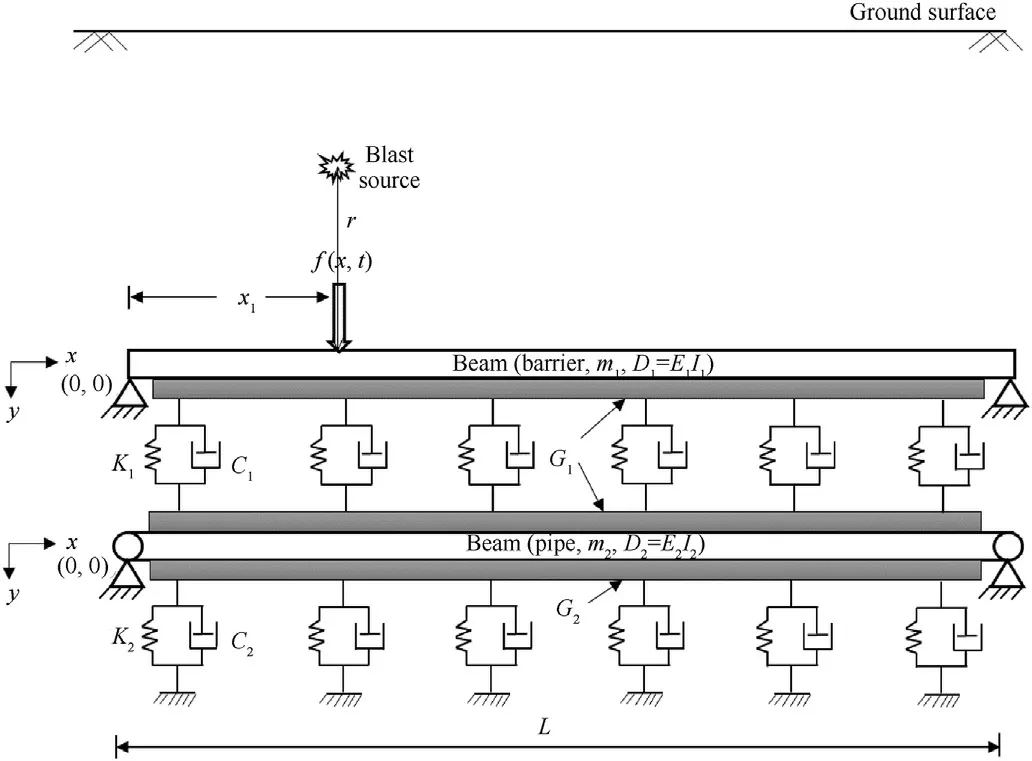
Fig.1.Mathematical model of the proposed formulation.
Both beams are considered as linear elastic Euler Bernoulli’s beam with a uniform cross-section.The concentrated forcef(x,t),resulting from subsurface explosion,is acting on the top beam(barrier) at a distance of x1as shown in Fig.1.For providing a generalized analytical solution it is assumed that the value of soil spring stiffness,damping coefficient and shear value of the shear interaction layer in between top and bottom beam and below the bottom beam are K1,C1,G1and K2,C2,G2respectively.Soil spring stiffness can be evaluated from the ASCE code[51].The location of blast source can be anywhere with regard to buried pipeline and henceforth the equation for spring stiffness will change accordingly as per the ASCE guidelines [51].However,for performing the parametric study it is adopted that blast location,barrier layer and the pipeline are in the same horizontal plane.Hence,following equations are used for calculating the lateral soil stiffness.
whereNchandNqhare bearing capacity factors,can be obtained from the curves or closed from expressions given by ASCE code[51].c,D,andHare the soil cohesion,pipe outer diameter,effective unit weight of soil and burial depth of pipe centreline respectively.Δh=0.04(H+D/2)≤0.10Dto 0.15D.
The shear parameter of the shear layer (G) can be calculated from the following equations [35,52]:
whereEsis Young’s modulus of soil,B is the width of the beam cross-section,γ describes the rate at which the vertical displacement in the ground reduces with depth,and νsis the Poisson’s ratio of soil.The range of γ is generally varied from 1.0 to 2.0 m-1[35,52].In the present study an average value of γ i.e.,1.5 m-1is taken.
The end boundary conditions of the beam may differ from free to fixed.Thus,as a logical approximation,intermediate boundary condition,i.e.,simply supported beam,is considered for both the beams [53]Hence,the existing boundary conditions are
However,in the present analysis pipe length is taken sufficient such that the end boundary effects on peak pipe response is negligible.Fig.2 depicts the distribution of blast pressure with time.In the present study,the negative phase of blast pressure is neglected due to very less magnitude of negative pressure compared to positive one.The change of blast pressure with time can be expressed by an exponential decay function [54,55]as follows:
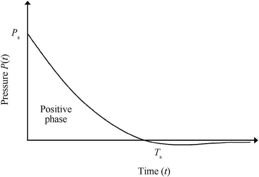
Fig.2.Distribution of blast pressure with time.
wherePsis the peak overpressure,Tsis the total time in positive phase for blast pressure distribution,andbis the decay coefficient which will take care the geometric damping while travelling the blast waves from source to point of interest.The decay parameter(b) can be estimated [56]using the following expression
whereZis the scaled distance and can be expressed as
soil type and can be attained from Bulson [57].The values ofkparameter for some soil types are listed in Table 1.From Table 1,it is noted that if the soil is saturated the value ofkis substantially increased and hence corresponding blast load will also increase.Eqs.(11) and (12) are in the Imperial unit’s system.
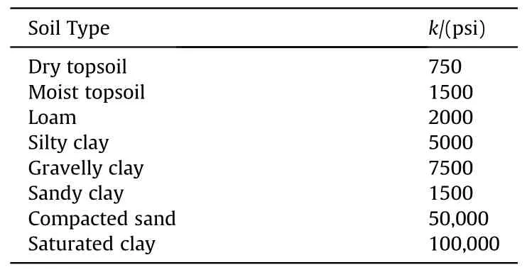
Table 1 k parameter for different soil conditions [57].
The blast forcef(x,t)of Eq.(10)can further be expressed in the following shortened form
3.Governing coupled differential equations and closed-form solutions
The governing differential equations of top and bottom beam as shown in Fig.1 can be stated as
where,ris the distance from the center of the TNT charge to the point of interest on beam in meters (m),andwis the mass of the TNT charge in kilograms(kg).
The blast force per unit length of the beam acting at a point(x=x1) as shown in Fig.1 can be stated as
whereBis the width of the top beam,which is considered as outside diameter (B=D) of the buried pipe(bottom beam).
Further,peak overpressure (Ps) and duration of positive phase(Ts) can be estimated [57]from the following expressions:
wherefdepends on burial depth that can be achieved from the graph given by Bulson[57],thekparameter changes with changing whereD1=E1I1;D2=E2I2;m1andm2are the mass per unit length of the top and bottom beam respectively;y1andy2are the deflections of top and bottom beam respectively.The finite Sine-Fourier transform is employed in the present analysis to solve the prior mentioned coupled partial differential equations (Eqs.(14)and (15)).The finite Sine-Fourier transform is chosen as displacement at both the ends of the beam are known(Dirichlet boundary condition).The finite Sine-Fourier transform for space co-ordinatex(0 ≤x≤L)and its inverse can be expressed as follows:
wheren=1,2,3,…….
Applying finite Sine-Fourier transform for both sides of Eqs.(14)and (15) we get
the solution of Eq.(22) in modal form can be written as
where φnis the generalized eigenvector and qn(t)is the generalized coordinate vector.Now,substituting the value ofYn(t)from Eq.(28)into Eq.(22)and pre-multiplying by φTnon both sides of Eq.(22),the following expression is obtained.
now,Eq.(30) can further be reduced to
The complete solution of Eq.(34)is nothing but the sum of the complementary function (C·F) and particular integral (P·I) of Eq.(34).So,
it is assumed that beams are originally at rest condition.Hence for zero initial conditions
with zero initial conditions,the complementary part of Eq.(37)becomes zero.So,Eq.(37) further reduced to
the particular solution is obtained by adapting Duhamel integral[58].
Now,from Eqs.(28) and (41)
where,the expressions off(m,n)are listed in the appendix section(Eqs.(A1)-(A7)).Now,the deflection of both the top and bottom beam can be obtained using Eqs.(18),(19)and(43).Fig.3 depicted the step-by-step procedure of the present analysis.

Fig.3.Flowchart of the proposed methodology.
4.Validation of proposed method
The present formulation is authenticated with the outcomes procured from earlier studies [45,49,50].The validation with Nourzadeh et al.[45]confirms the correctness of blast load simulation and the applicability of the proposed mathematical model considering single beam system subjected to blast load.The validation with Hetenyi’s solution[49],and Maheshwari et al.[50]further confirms the applicability of proposed solution for double beam system.
Nourzadeh et al.[45]examined the response of buried pipeline to subsurface explosion through a simplified analytical study.The pipe was assumed as beam and soil as Winkler foundation.The study did not incorporate the influence of damping and shear layer for shear interaction between springs.For comparison study,pipe size ‘II’ and soil type ‘D’ are adopted in the present analysis.The detailed parameters about prior mentioned pipe size and soil type are reported by Nourzadeh et al.[45].In the present study,instead of a double-beam,the single beam resting on single parameters Winkler foundation concept is used to simulate the formulation proposed by Nourzadeh et al.[45].The governing differential equation is solved by the finite Sine Fourier transform method.Pipe strains are recorded as an output of the formulation.Under given conditions,the pipe strain of steel pipe,PVC pipe,and PE pipe obtained from Nourzadeh et al.[45]and the present study are 0.01%,0.03%,and 0.30% respectively,and 0.0128%,0.0261%,and 0.3097% respectively.This relative study approves the rationality of the proposed solution.
Further,Maheshwari et al.[50]proposed a closed-form analytical solution for beam on reinforced granular bed subjected to a concentrated load based on the concept of double-beam system.Both the top foundation and bottom reinforced layer were idealized as beams and the soil was idealized as Winkler springs.However,the solution did not consider the shear interaction between individual springs.Maheshwari et al.[50]validated their analytical formulation with Hetenyi’s solution[49].For the present validation purpose,finite Sine-Fourier transform is employed to solve the governing differential equations of the double-beam system as proposed by Hetenyi[49]and later on adopted by Maheshwari et al.[50].The relative flexural rigidity of beam (D1/D2) and relative stiffness of soil(K1/K2)are 10 and 5 respectively.Where K1and K2are the soil spring stiffness of the top and bottom layer respectively.The results obtained from the present approach and past studies[49,50]are depicted in Fig.4.Results are plotted in normalised form as mentioned by Maheshwari et al.[50].The expressions for normalised distance (Xn) and normalised deflections of the top and bottom beams (i.e.,andrespectively)are as follows:
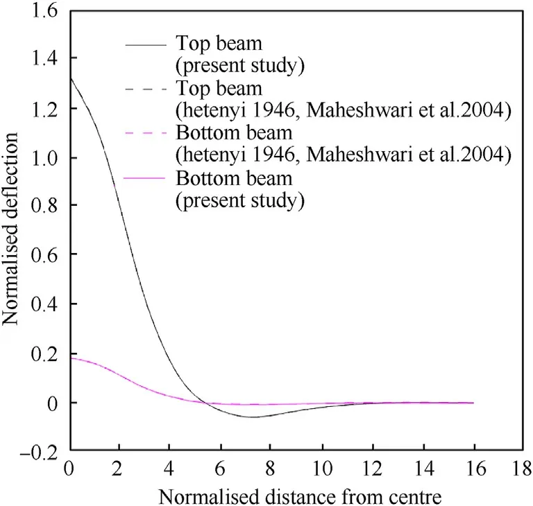
Fig.4.Comparison of displacement of top and bottom beams.
where,Qtis the load applied on the top beam.are the characteristic lengths of the top and bottom beams respectively.
From Fig.4,it is perceived that the results obtained from the present formulation are identical with the past studies.Hence,this validation further confirms the sanctity of the proposed mathematical model.
5.Parametric study
In the subsequent sections,a parametric study is carried out to investigate the response of buried pipe with and without barrier subjected to subsurface explosion by varying TNT charge weight(w),the pipe material,damping ratio(ξ)and TNT offset.The impact of relative barrier-pipe flexural rigidity on pipe response is also studied.The required parameters to perform the parametric study are shown in Table 2.
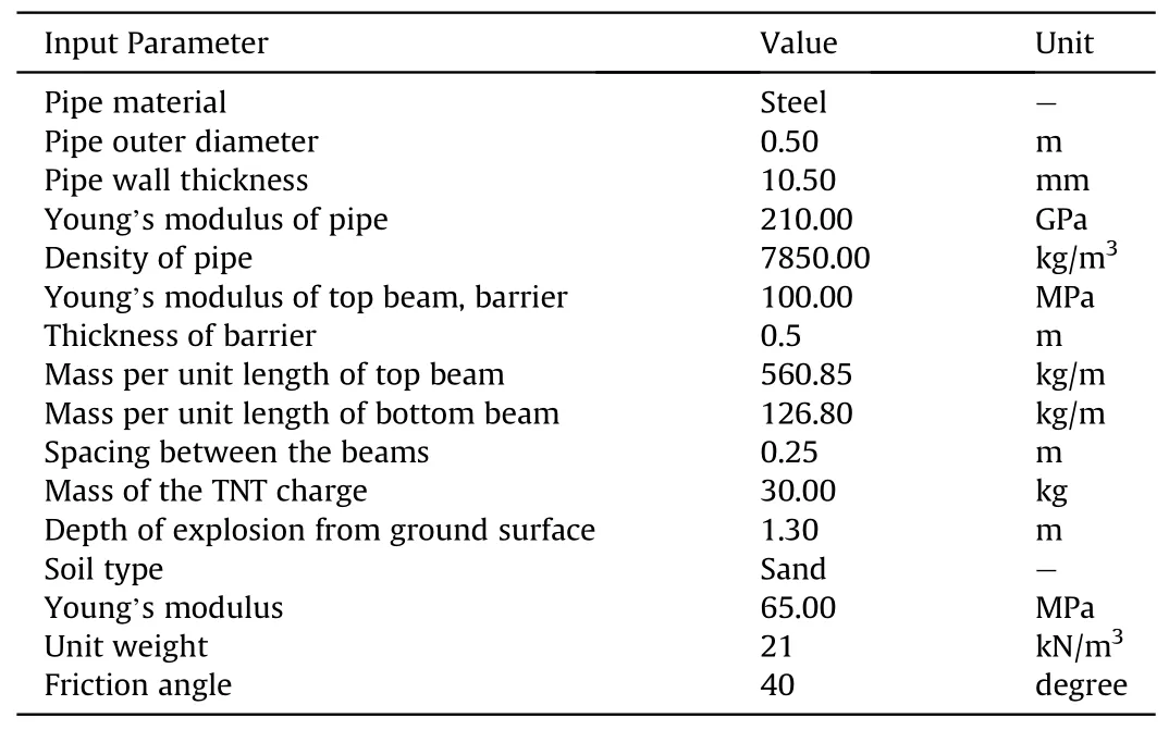
Table 2 Soil-pipe-barrier-blast parameters to perform the parametric study.
5.1. Influence of TNT charge weight
To understand the influence of charge weight (w) on pipe response,the range ofwis taken from 5 to 30 kg,and other parameters are kept constant as listed in Table 2.The maximum deflection of both double-beam system (pipe with barrier) and single beam system(pipe without barrier)and corresponding peak pipe bending strains are recorded and are shown in Fig.5.
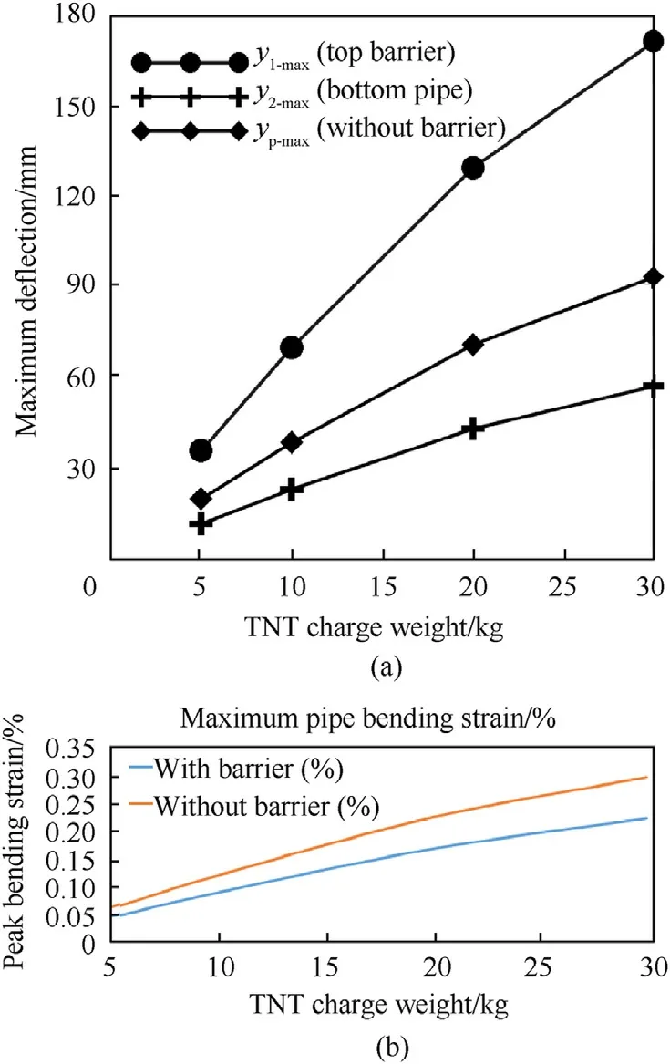
Fig.5.Influence of TNT charge weight on (a) maximum pipe deflection and (b)maximum pipe bending strain.
From Fig.5(a),it is seen that the peak displacements for both the cases are increases with increasing charge weight(w).For instance,in the case of double-beam system,the maximum displacement of the pipe (y2-max) is increased from 12.08 to 57.31 mm with increasingwfrom 5 to 30 kg.Similarly,in the case of a single beam system,the maximum displacement of the pipe (yp-max) is raised from 20.25 to 93.15 mm with increasingwfrom 5 to 30 kg.Further,it is perceived that the response of pipe is drastically reduced for pipe with barrier system compared to pipe subjected to explosions without any barrier.For instance,forw=30 kg the maximum displacement of pipe is reduced from 93.15 to 57.31 mm due to the present barrier system.Similar observation is found in case of peak pipe bending strain as well (Fig.5(b)).
5.2. Influence of pipe material
In this section,four different types of pipe materials namely X-65 grade of steel,Concrete,polyvinyl chloride (PVC),and High-Density Polyethylene (HDPE) pipe are considered to examine the impact of pipe materials on peak pipe response.The results are listed in Table 3 in terms of maximum displacement.

Table 3 Maximum pipe deflection for different pipe material.
From Table 3,maximum pipe response is observed for HDPE pipe (maximum pipe deflection of 114.64 mm and 272.63 mm for with and without barrier respectively).Whereas,minimum pipe response is calculated for X-65 steel (maximum pipe deflection of 57.31 mm and 93.15 mm for with and without barrier respectively).This is due to the change of bending stiffness with changing the pipe materials.
5.3. Influence of damping ratio
Fig.6 shows the effect of damping ratio(ξ)on pipe response.The extent of damping ratio (ξ) is chosen from 5% to 25% with an increment of 5%.
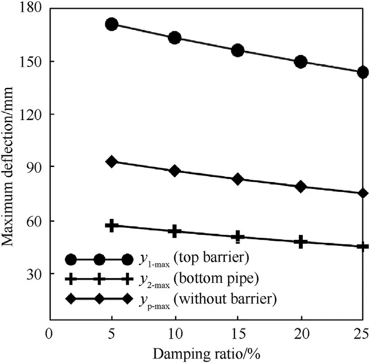
Fig.6.Influence of damping ratio on maximum pipe deflection.
From Fig.6,it is apprehended that the maximum pipe deflections are reduces for both the pipe with and without barrier with increasing the value of damping ratio as expected.For instance,in the case of a double-beam system,the maximum displacement of the pipe(y2-max)is reduced from 57.31-45.35 mm with increasing ξ from 5%-25%.Similarly,in the case of single beam system,the maximum displacement of the pipe(yp-max)is reduced from 93.15-75.34 mm with increasing ξ from 5%-25%.
5.4. Influence of TNT offset
TNT offset presents the distance from the source of explosion to the top of the barrier layer (top beam).In the present study,four different offsets such as 5 m,7 m,9 m and 12 m are considered.
From Fig.7,it is shown that peak pipe response(deflection and bending strain) reduces with increasing the explosive offset.With increasing the TNT offset,blast source is moving away from the pipeline,hence peak overpressure is getting reduces while blast waves passing through the soil media.For example,peak pipe displacement is reduced from 57.31 to 5.28 mm and from 93.15 to 9.49 mm for pipe with and without barrier respectively with increasing TNT offset from 5 to 12 m.
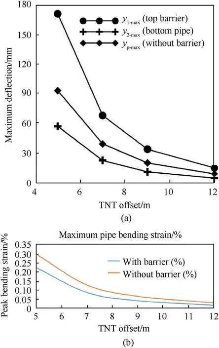
Fig.7.Influence of TNT offset on(a)maximum pipe deflection and(b)maximum pipe bending strain.
5.5. Influence of relative barrier-pipe flexural rigidity
In order to obtain the impact of flexibility of barrier system on pipe response,the ratio of barrier to pipe flexural rigidity(D1/D2)is varied from 0.001 to 1000 i.e.,from very flexible barrier to extremely rigid barrier system with respect to pipe.The recorded peak pipe deflection and peak pipe bending strain are normalised with the corresponding maximum values recorded atD1/D2equal to 0.001 and are shown in Fig.8.From Fig.8 it is found that normalised peak pipe deflection and corresponding bending strain reduces with increasing the rigidity of the barrier layer.
6.Identification of influential soil and pipe input parameters
In this section a range of soil and pipe parameters are chosen as input by keeping all other parameters constant to obtain the influential parameters.The lower and upper limits of the input parameters are listed in Table 4.

Table 4 Modeling parameters and their lower and upper limits for the central composite design (CCD).
The central composite design(CCD)methodology is adopted to obtain the optimum number of combinations of seven input parameters.CCD is one type of response surface design and it has the capability of full quadratic model.CCD analysis suggested total 152 combination of seven input parameters.Hence,the response in terms of peak pipe displacement (for with barrier system) are recorded using Matlab corresponding to 152 combination of input parameters.The data are further analysed using statistical program Minitab to get the most influential input parameters.The confidence level is chosen as 95% for the statistical analysis.Statistical results are plotted in terms of Pareto chart and Normal plot of the standardized effects as shown in Figs.9(a) and 9(b) respectively.Fig.9(a)depicts the absolute values of the standardized effects from the maximum effect to the minimum effect.The reference line in the Pareto chart is based on the significance level (α).Significance level can be calculated by deducting confidence level from the unity.The parameters that cross the reference line (1.98 in the present Fig.9(a))are statistically significant.Hence,from Fig.9(a)it is understood that most significant parameter is the bar that represent term‘A’that is nothing but the soil spring stiffness(K).Further,it is noted that parameters A,E,D,B,and G(i.e.,K,E2,D,G and t) are statistically significant.C and F (i.e.,L and ρ) are not significant parameters.Pareto chart is not able to determine whether the change in the value of input parameters increase or decrease the response.However,Normal plot is able to depicts both the magnitude and direction of the effects as shown in Fig.9(b).The parameters those are further from zero on the X-axis are statistically significant.The positive effect indicates that the response increases with increasing the value of the parameter and negative effect indicates that the response decreases with increasing the value of the input parameters.Fig.9(b)it is noticed that parameter D i.e.,pipe diameter(D)has the positive standardized effect and the parameters G,B,E,and A (i.e.,t,G,E2,and K) have negative standardized effects.Hence,peak pipe displacement increases with increasing the value of pipe diameter (D) and peak pipe displacement decreases with increasing the values of pipe wall thickness(t),shear parameter (G),Young’s modulus of pipe (E2),and soil spring stiffness (K).
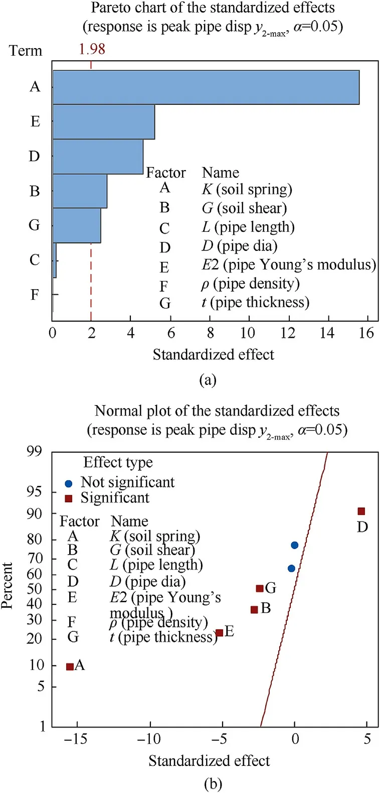
Fig.9.(a) Pareto chart and(b)Normal plot of the standardized effects for seven input parameters.
7.Summary and conclusions
The present work examined the dynamic response of a doublebeam system subjected to blast loadings to simulate the behaviour of buried pipeline with barrier system under subsurface explosion.Both the buried pipe and the barrier are idealized as Euler Bernoulli’s beams and surrounding soil is idealized as viscoelastic foundation along with shear interaction between isolated Winkler springs.The proposed solution is authenticated with the results procured from previous studies [45,49,50].Further,a parametric study is carried out to inspect the impact of TNT charge weight(w),pipe material,damping ratio (ξ) and TNT offset on the response of buried pipe in terms of peak pipe displacement considering both with and without barrier system.A statistical analysis is also executed to obtain the most influential soil and pipe input parameters.The present analysis involved less input parameters compared to the FEM based three-dimensional numerical analysis,and due to simplified assumptions in the current analytical solution,the present study is less time consuming compared to detailed continuum based analysis.Hence,in the initial design phase,the proposed formulation can be implemented to get quick results with moderate accuracy without performing complex numerical study or expensive experimental work.Following are the salient points based on the present study.
· The present closed-form analytical study can be utilized to acquire the response of buried pipe with and without barrier system under subsurface detonation.Hence,the proposed formulation can be used as an alternative to costly experimental or numerical study.
· The barrier system substantially reduces the displacement of buried pipes subjected to underground explosions.Hence,a suitable barrier system can be provided to protect important underground pipeline networks from blast loadings.
· Pipe deflection magnifies with increasing the weight of the TNT.
· Pipe deformation varies with changing the pipe material due to the change in pipe bending stiffness with changing pipe material.
· Pipe deflection decreases with increasing the damping ratio as expected.
· Pipe deformation reduces with increasing TNT offset.
· Pipe stability increases with increasing the rigidity of the barrier layer.
· From statistical study,it is observed that among seven input parametersK,E2,D,Gandtare statistically significant.However,Land ρ are not significant parameters.
The future scope of the present study is to incorporate plasticity and non-linearity of soil and pipe material.
Funding
This research did not receive any specific grant from funding agencies in the public,commercial,or not-for-profit sectors.
Author contributions
Conceptualization,methodology,validation,writing-original draft preparation,by C·H·C;supervision,writing-review,and editing by D.C.
Declaration of competing interest
The authors declare that they have no known competing financial interests or personal relationships that could have appeared to influence the work reported in this paper.
Appendix
The expressions off(m,n) of Eq.(43) are given as follows:
杂志排行
Defence Technology的其它文章
- High-Velocity Projectile Impact Behaviour of Friction Stir Welded AA7075 Thick Plates
- Influence of liquid bridge force on physical stability during fuel storage and transportation
- Adaptive fuze-warhead coordination method based on BP artificial neural network
- Investigation on the ballistic performance of the aluminum matrix composite armor with ceramic balls reinforcement under high velocity impact
- Cooperative multi-target hunting by unmanned surface vehicles based on multi-agent reinforcement learning
- AI-based small arms firing skill evaluation system in the military domain
