Design of Multi-layered Protection Against Guided Mortar Threats Yhrough Numerical Modeling
2023-12-07BonnyThawaniSengKiatLimLauraBrownRichardCritchleyRachaelHazael
Bonny Thawani,Seng Kiat Lim,Laura Brown,Richard Critchley,Rachael Hazael
Cranfield Forensic Institute, Cranfield University, Defence Academy of the United Kingdom, Shrivenham, SN6 8LA, UK
Keywords: Hydrocode Fragmentation High velocity Composite structures Foams
ABSTRACT The trade -off between protection and weight is a constant consideration when designing a portable protective solution.Greater mobility is a desirable attribute and protection must therefore adapt,prompting a demand for lightweight,simple to construct,low-cost and effective ballistic protection systems.High strength and ductility,wave spreading capability and good energy absorption are key properties for ballistic protection.Four materials,polycarbonate,Kevlar®-epoxy,polyurethane foam,and aluminium alloy,possess these properties and were selected for analysis by numerical simulation.Multilayered configurations were proven to be an optimal solution,by exploiting the advantages of each material without having large penalties of mass and cost.Numerical modelling using ANSYS AUTODYN®is used to simulate monolithic and multi-layered target configurations,to obtain the penetration mitigation performance.The results are analysed to select configurations based on different requirements,such as lowest cost,lowest mass,best performance,and optimal configuration which balanced the three key parameters mentioned.The optimal configuration of Aluminium,Kevlar-Epoxy,Polyurethane,and Polycarbonate has layers with thickness of 7,3,38,2 mm respectively with a total mass of 7.97 kg,total cost of $39.86 and penetration of 29.34% (14.67 mm).Polynomial relationships between performance and mass/cost are also determined.
1.Introduction
It has been identified that precision mortar attack (aside from improvised explosive devices (IED))proved to be one of the major threats encountered by security personnel,as it has a circular error probable (CEP) of less than 5 m [1,2].Circular error probable is defined as a measure of weapon system precision where 50% of the rounds will land in the defined radius.Subsequently,the use of mortars has proven to be the cause for over 30% of casualties(more than 5000) and property damage in recent conflicts in the middle east [3-6].The development of ammunition has led to improved blast and fragmentation effects,which can undermine the protection capabilities of the gabion structures [7].According to Elshenawy [7],it was concluded that a multi-layered structure of five layers combining steel,sand,aluminium-polyurethane foam sandwich panel,with a total thickness of 35 cm,is required to mitigate steel mortar warhead fragments with velocity of 1100 m/s.
Similar to most anti-ballistic systems [8],such a lightweight solution requires the following properties to mitigate fragment penetration.
(1) High strength and ductility to impede the shock transmitted from the impact energy of the high velocity fragment;
(2) Wave spreading capability to distribute the energy of the shock wave in material instead of passing the energy through it;
(3) High energy absorption capability to absorb kinetic energy and convert it to heat energy or other internal energy[9-12,12].Therefore,the material needs to have high ductility so that it can undergo significant plastic deformation with large energy absorption and avoid the material having sudden failure that may result in secondary fragments [13].Advances in materials sciences have provided new materials that have the properties previously described but are also lightweight.Composite armour,which incorporates air spaces,ceramics,plastics in addition to steel,provides a lightweight yet high strength alternative to RHA.
An alternative lightweight material is polycarbonate.Polycarbonate is a rigid thermoplastic that is designed to soften when heat is applied such as the impact energy generated by fragments[14].This allows the polycarbonate to melt at the high temperature generated by the impact and “wrap” around the fragment in its liquid state thereby slowing it down [14].This is unlike other materials,such as ceramic plates,that are brittle and may shatter upon impact and make them less effective for stopping additional impacts at the same location.Polycarbonate has good impact properties [15]and is pliable,which make it easier to fabricate to the required shape,thereby lowering the manufacturing cost [14].Polycarbonate is therefore often used as the material for “bullet resistant glass”.
Another candidate material for high strength and ductility are aramid fibres.Aramid fibres,have a high strength to weight ratio and are five times stronger than steel [16].This material also has high tensile strength of 3620 MPa[16]and large energy absorption capability,making it an ideal material for ballistic protection.This is due to its chemical structures having long straight parallel monomers chains that are interconnected with strong hydrogen bonds through further processing.However,aramid fibres are rapidly degraded by ultraviolet (UV) light and moisture,which led to significant loss of strength and stiffness.The aramid fibres will need to be coated with UV stabilisers and combined with water resistant materials,such as epoxy,to protect it from the UV and moisture[17].Lastly,it is difficult to machine due to its high strength and therefore leads to a higher production cost for the product [18].
Aluminium alloys are also a candidate material with high strength and ductility,yet light weight when compared to other metals like steel.Aluminium has a density of about 2700 kg/m3[19],which is about 2.9 times less than steel and 1.4 times less than aluminium ceramics.Therefore,it is heavier when compared to both polycarbonate and aramid fibres.
Besides aramid fiber composites,porous material also demonstrates high energy absorption capability[18,20].A porous material is a solid permeated with interconnected network of pores that is filled with fluid (liquid or gas) [21].The pores distend the solid material with the result that the porous material has a smaller density and larger volume than its crystalline form Refs.[22-24].
Closed cell (also known as rigid) porous metal or polyurethane(PU) foam are used in military applications,such as mine protection,to absorb blast waves’ energy [25].As closed cell foam is denser than open cell foam,it provides a more rigid structure for the system and better energy absorption capability.Based on experimental data and numerical simulation using AUTODYN®,Boey[26]concluded that PU foam provides a significant reduction in weight despite having a limited increase in penetration,when compared to aluminium (Al) metal foam.
To maximise the effectiveness of materials,especially when lightweight is a requirement,researchers often look employ multilayered configurations.Multi-layered configurations for ballistic protection have been extensively studied [27-32],often highlighting their superior mass to ballistic protection performance.One of the most effective ways that high ballistic resistance is achieved is through impedance mismatch.Verreault’s numerical modelling and experimentation [33]shows that multi-layered configuration with alternating impedances material,is able to mitigate sympathetic detonation by scattering away more shock energy and increase in energy absorption.This means that the velocity of the fragment can be greatly reduced.The experiment shows that higher impedance mismatch between material results in less energy transmitted to the final target.
Sueki’s study[31]highlighted the importance of the sequence of alternating impedance material.The penetration protection is better when low impedance material (i.e.polyethylene/polycarbonate) is inserted between high impedance materials (i.e.aluminium/steel) as compared to the alternate sequence where high impedance material is in between low impedance material.This is because the excitation frequency of the propagated stress wave was lowered due to the reflected wave caused by the high impedance mismatch [31,33].
Besides the observation above,Boey [32]and Poh [34]further suggested the sequence of the material to be impeding layer,wave spreading layer,porous layer and follow by the support layer.Experimental and numerical study from Boey [32]shows that the multi-layer configuration is effective in stopping fragments with velocity of about 500 m/s from perforating through the layers.
The use of numerical methods for testing the performance of the protection system provides a cost-effective alternative to dependence on experimental methods.Numerical methods allow the user to accurately visualise the response of the system when it is subjected to loading due to high velocity impact.Additionally,the large material libraries available in simulation software provide the user with a range of materials to experiment with,thus increasing the versatility of the study.In terms of versatility,numerical methods allow for testing with a range of geometries,that would otherwise be costly if done physically.Furthermore,use of hydrocodes allow the user to quantify data that would otherwise require expensive sensors and specialist setups to measure.In the case of high energy impact events (such as this study),use of numerical methods is a safer choice as compared to physical experiments.Although,it is important to point out that experimental validation of results from numerical studies is necessary to account for inaccuracies and incomplete data in material models.
While much literature is focused on improving two areas such as mass reduction and penetration protection performance,it is found that optimisation on cost or on all three parameters are lacking.Therefore,this study aims to find an optimised solution that considered all three parameters.
2.Methods and model setup
2.1. AUTODYN® hydrocode simulation settings
A 2D Lagrange model with axial symmetry was developed using ANSYS AUTODYN,in which rotation symmetry about the axial is assumed to form a cylindrical target shape.The details of the models used in this study are outlined in subsection 2.2.
To establish the optimum mesh size,a fidelity study using element sizes of 1 mm (baseline),0.5 mm and 0.2 mm was undertaken.The simulations took approximately 15,25 and 200 min,and resulted in a depth of penetration difference of 6.0% and 9.1% against the baseline respectively (Table 1).To balance computational time and accuracy,an overall mesh element size of 0.5 mm(2 cells per mm) was selected,coupled with gradient zoning of 0.1 mm at the region of impact (lower portion in J direction for 10 mm radius out of the total 50 mm).

Table 1 Fidelity study for mesh size.

Table 2 Details the material,function,and model data for the simulation studies.
To understand localised responses during the impact event,a series of moving gauges were placed axially on the fragment at 0.5 mm,while fixed gauges were placed on the target at 1 mm intervals.
2.1.1.Material model
All materials used the material models provided with the AUTODYN library,except for the porous material.For porous material,only the solid EOS is present in the material library,therefore,theP-α EOS [35]is used.The following parameters were required for the porous material model.
(1) Initial density of the porous material [25].
(2) Bulk sound speed in the elastic compaction region
(3) Maximum elastic pressure(pressure at yield)
(4) Solid compaction pressure
(5) Solid Hugoniot parametersCandS[35]
The porous density is 0.16 g/cm3obtained from supplier datasheet [25].Using formulas from Grady and Winfree on PU foam[40],the remaining porous material data can be calculated.The bulk sound speed,ceis obtained based on the following equation:
where κ (Pa) is the bulk modulus (Pa) and ρ0(kg/m3) is the initial density.
whereE(Pa)is the Young Modulus and υ is Poisson ratio,which is 0.3 based on the datasheet.
The Young Modulus can be derived from the relationship with shear modulus,G.G(Pa)which is from the datasheet with the value of 75.2 MPa[25].
This can be input back to Eqs.(2) and (3) to obtain a bulk modulus of 488.8 MPa and bulk sound speed of 1747.86 m/s.The bulk sound speed is similar to that experimentally recorded by Marsh [41]of about 1732 m/s.
The initial compact pressure,Pewas determined based on the yield stress data obtained from the datasheet(1.55 MPa).The solid compaction pressure,Psis the pressure for which the porous material reaches a density equal to that of its solid counterpart.Based on the LASL shock equation of state by Marsh [42],the valuePsis 1.729 GPa as found under the graph of PU foam 0.16 g/cm3.Lastly,the solid EOS for porous material can be obtained from the AUTODYN® material library.
2.2. Model setup
As highlighted in the aim of this study,there will be simulations on two main configurations to understand their performance.The first set of configurations will be based on monolithic targets using the individual material listed in Table 3,to identify their performance.The second set of configurations will be based on multilayered composites of these material based on the layout in Fig.1.
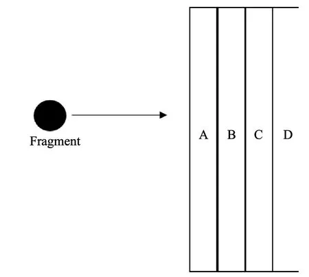
Fig.1.Proposed multi-layered target of 50 mm thickness: Layer A -Impeding layer;Layer B -Wave spreading layer;Layer C -Porous layer;Layer D -Supporting layer.

Table 3 Sub-configuration for monolithic targets.
2.3. Configuration 1 - monolithic targets
Four monolithic targets materials (Table 3) were simulated to determine the penetration protection capabilities of three thickness of 6,20 and 50 mm 6 mm thickness is based on Ref.[43]where 6 mm thickness of CFRP has similar penetration depth regardless of the target geometry,lay-up,sequence,production method or fibre orientation.
50 mm thickness is based on existing commercial target plates,such as the Mifram security modular ballistic protection[44],while 20 mm thickness is used as it is readily available,and an intermediate between 6 mm and 50 mm.It should be noted that should no perforation of the smaller thickness layer occur,the larger thicknesses are not simulated.
For each target,the height (radius for 2D axial) of 280 mm is used,as it has the same area size1based on target plate of 500 mm by 500 mm.This size is selected,as it is of a manageable real world handling size and is similar to the commercially available systems[45].
2.4. Configuration 2 - multi-layered targets
Twelve multi-material configurations of fixed material order,with thickness 50 mm were simulated to optimise based on perforation resistance,mass,and cost.Each multi-layer target had a fixed layer arrangement of Aluminium-Kevlar Epoxy-Polyurethane-Polycarbonate (AL-KE-PU-PC) (Fig.1).AL forms the first impedance layer in view of its higher density as compared to the other materials.This provides a greater impedance effect to slow down the fragment.KE shall then be used as the wave-spreading layer to further mitigate the velocity of the fragment using its anisotropic properties.PU foam shall then be used as the filler,in view of its low mass and cost,and “shock absorber” of the target system as it has good pressure reduction properties.The great impedance mismatch shall also increase the shock reflection,thereby further reducing the shock transmitted to subsequent layers.PC shall be used as the support layer and shall be efficient stopping the low residual velocity fragment.
Composite protection systems consist of multiple layers and materials that improve the system’s penetration protection performance.The impeding layer reduces the shock transmitted from the initial impact.The function of the wave spreading layer is to dissipate kinetic energy from the projectile in the axis perpendicular to the direction of impact.The porous layer absorbs any remaining kinetic energy when the pores undergo compaction under loading.Finally,the support layer prevents spalling from the porous layer for effective energy absorption [32]and provide additional layer to further mitigate penetration.For this study,the candidate materials for the impeding,wave spreading,porous,and support layers are aluminium alloy,aramid fibre (Kevlar®-epoxy),polyurethane foam,and polycarbonate,respectively.
For each configuration,material layup thicknesses were selected based upon an iterative process.The iteration of the target thickness starts with 6 mm AL and 6 mm kE,together with a constant thin 2 mm PC,and the remaining portion will be filled with 38 mm of PU.The thickness of AL and KE was then changed systematically in 1 mm variations (Table 4).6 mm thickness of AL and KE was selected based on their effective penetration protection with respect to cost and mass,respectively.

Table 4 Configuration for multi-layered targets.
Configuration were also bound based upon their overall cost and mass.By considering the behaviour of the monolithic plates.Firstly,monolithic targets plates that resisted perforation were used as reference with respect to mass,and cost of the multi-layered targets.As shown in Table 4,a 20 mm AL monolithic target (0.25 m2face area)shall require 13.32 kg and a 15 mm kE monolithic target shall approximately cost$175.93.These two shall be the boundary values for the optimisation of cost and mass.
2.5. Model validation
An impact between the fragment and target is used to validate the AUTODYN®hydrocode.The simulation result,in particular the impact pressure,can be compared with theoretical calculation through impedance matching to ensure good agreement of results.This would then give confidence in the set up for the subsequent simulation.
1It is assumed to be 80% of the remaining weight (4.2 kg minus 0.75 kg) of the mortar,discounting the weight of charges that will not be part of fragments.
The material specification used for the code validation is shown in Table 5.The C,S and density are obtained from AUTODYN®material library.

Table 5 Material specification for code validation.
The set up shown in Fig.2,involves a steel 1006 fragment of 6 mm thickness and 2 mm height with a constant velocity,UDof 1000 m/s.The target is made of polycarbonate with a 6 mm thickness and 10 mm height for unsymmetrical impact.Gauges are set up at 1 mm intervals to collect peak pressure data to compare with theoretical analysis.Material data are based on AUTODYN®library,in particular the shock coefficient C1 and S1 in Table 2 shall be used for calculation.
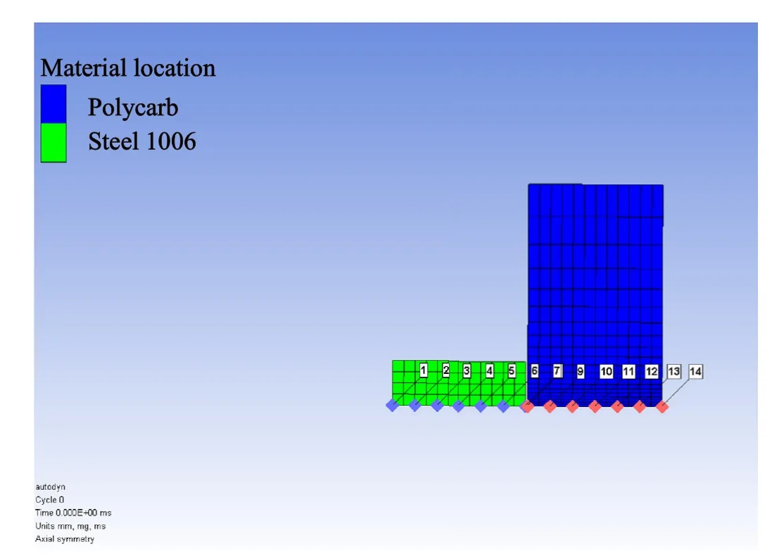
Fig.2.Code validation set up using a sample model for high velocity impact between steel projectile (Green) and polycarbonate target (Blue).
The peak pressure at the polycarbonate target is 9.76 GPa at the time of 3.7 × 10⁻⁴ms,as shown in Fig.3.Correspondingly,the pressure gradient at about 3.3 × 10⁻⁴ms is shown in Fig.4.From observation,the shock wave takes on a triangular profile where the shock wave front is being relieved laterally as it moves through the target.This result in the pressure to rise and drop rapidly when the fragment moves through the respective points in the gauges.This is expected as the fragment is smaller than the target,which will release its energy to the side when impacted.
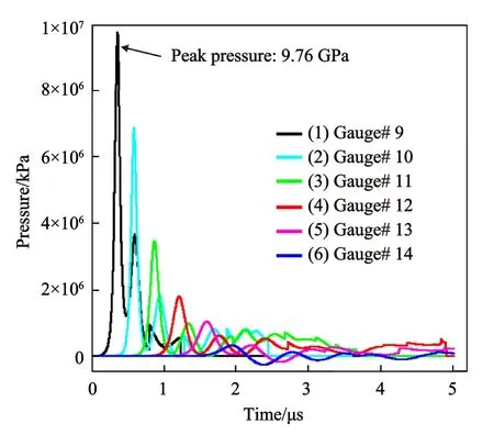
Fig.3.Peak pressure at different locations on the target against time when steel projectile impacts polycarbonate plate.
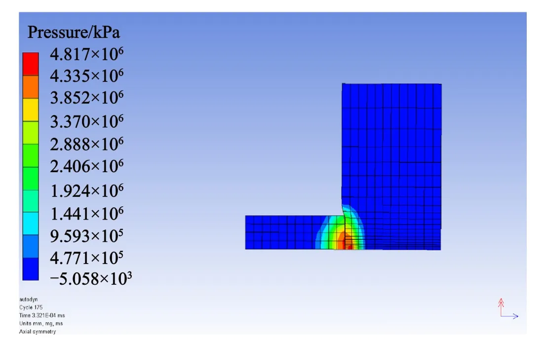
Fig.4.Pressure gradient at the interface between steel projectile and polycarbonate plate at 3.3 × 10⁻⁴ ms during a high velocity impact event.
To compare the results,shock impedance matching is used where the pressure on the fragment,P1,will be equal to the pressure on the target,P2,when impacted.Based on Kerley [46]the equations forP1andP2are as follows:
where ρ0refers to density,S and C refers to the coefficient from shock Hugoniot terms found in Table 5,UDrefers to the impact velocity and uprefers to the particle velocity.The two equations can then be equated to form the following quadratic equation to solve for the particle velocityup.
Substituting the values and by using a quadratic solver,upis found to be 764.2 m/s.As a check,this particle velocity is substituted into Eq.(6) andP1is found to be 9.16 GPa.This theoretical value is in close agreement to the simulated value of 9.76 GPa.Therefore,this simple validation provides the confidence that the code is suitable for subsequent simulations.
2.6. Experiment setup
Experimental validation of the simulations was done using an Explosive Low Velocity Impact System(ELVIS)to fire a projectile at the multi-layered target.The target configuration selection was done based on the lowest mass;lowest cost;highest protection;and the optimal choice between these factors(discussed further in subsection 3.2.1).The aluminium,polyurethane foam,and polycarbonate were procured commercially,while the Kevlar-Epoxy plates were manufactured in-house (Easy Composites resin infusion kit).A digital vernier caliper (Proster PST140) was used at random points on the plate’s edge to ensure that the plate was of the correct thickness,and it had no irregularities.Fig.5 shows the experimental setup for the experimental validation of the simulations.
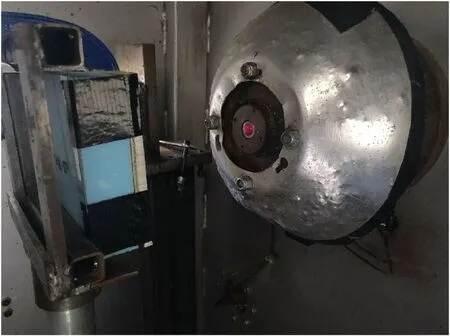
Fig.5.Multi-layer target setup in ELVIS before being impacted by 5 mm steel projectile at 400 m/s.The target face is Aluminium,followed by Kevlar-Epoxy,Polyurethane foam,and polycarbonate.
The simulation setup could not be adequately replicated experimentally,due to the large size of the target.Therefore,the target size was scaled down,alongside the impact velocity of the projectile to maintain the kinetic energy: target mass ratio.The target size was reduced to 150 mm×150 mm×50 mm.As a result,the impact velocity was reduced to 400 m/s.Furthermore,simulations with the material models were run with the new impact conditions to validate the multi-layer protection system design.The impact regimes for both cases,400 m/s impact and 1500 m/s impact,are not hydrodynamic.As a result,validation of the material models for impact at the lower velocity can be used to prove the validity of the models in the high velocity impact scenario.
3.Results and discussion
3.1. Monolithic targets
The results of each monolithic configuration are given in Table 6,where all materials exhibited perforation at 6 mm.As plate thickness increased,plate perforation began to reduce for all materials,except for the foam which perforated at all thicknesses.For each of the monolithic materials,a ductile piercing behaviour occurred,while the Kevlar®-epoxy demonstrated an abnormal failure mode.As Kevlar® typically fails through delamination,the observed behaviour is likely a low fidelity representation of this failure mode.While a higher fidelity mesh would likely correct this phenomenon,its use would increase computation time [47].

Table 6 Results for high velocity impact of steel projectile on 6,20,and 50 mm monolithic target plates.
3.2. Results for configuration 2 - multi-layered targets
To adequately design multi-layered targets,the performance of the individual targets needs to be known.The simulation results of each monolithic configuration are given in Table 6,where all materials exhibited perforation at 6 mm.As plate thickness increased,plate perforation began to reduce for all materials,except for the foam which perforated at all thicknesses.For each of the monolithic materials,a ductile piercing behaviour occurred,while the Kevlar®-epoxy demonstrated an abnormal failure mode.Further details of the performance of monolithic targets are available in Supplementary Information.A summary of the simulation results based on the multi-layered target configuration are tabulated in Table 7.The penetration performance in terms of percentage of the total thickness and dynamic deflection are extrapolated from the models as per the example shown in Fig.6 (see Table 7).
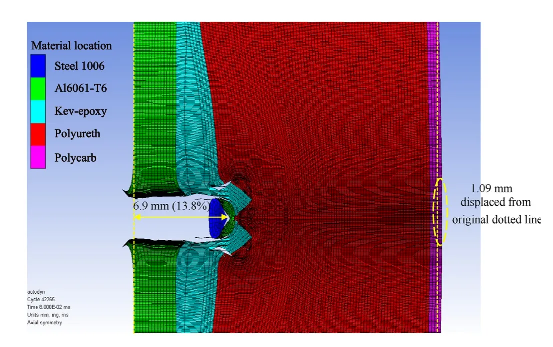
Fig.6.Example of examining the penetration of projectile into multi-layered target and subsequent dynamic deflection of target.

Table 7 Results for high velocity impact of steel projectile on multi-layered targets.
From Table 8,one can observe that the combined thickness of the first two layers (Al and KE) have an impact on penetration performance.The larger the combined thickness,the lower the penetration.For combined thickness of 10 mm (i.e.Configuration 2C,2G and 2I),the penetration is greater than 29%(14.5 mm)of the total thickness.For combined thickness of 11 mm (i.e.Configurations 2 B,2 F and 2 K),the penetration ranges from 13.4% to 18.5%,i.e.from 6.7 mm to 9.3 mm.For combined thickness of 12 mm(i.e.Configuration 2 A,2 E and 2 L),the penetration is the region of 10%(5 mm) of the total thickness.The penetration further reduces to below 10% for combined thickness of more than 13 mm(i.e.2D and 2H).

Table 8 Average performance specifications for combined thickness of Al and KE layers in a multi-layer protection system.
Although greater combined thickness provides better resistance to penetration resistance,the effectiveness diminished after 12 mm as shown in Fig.7.This is supported by the average specifications(i.e.mass,cost,and penetration) tabulated for each combined thickness in Table 11.At the combined thickness of 12 mm,the penetration protection has the greatest improvement of 68%,but with high cost increment.Beyond 12 mm,the improvement is minimal at 72% and 74%,with the increase in average mass and cost to be high.Therefore,the optimal combined thickness of AL and KE should be less than 12 mm.
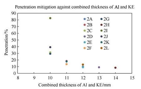
Fig.7.Penetration mitigation against the combined thickness of Al/KE layers when a multi-layered target is subject to high velocity impact from a steel projectile.
2Charge length is calculated by dividing the charge volume by charge area.Charge volume is calculated from HE weight divided by HE density.
The second observation is on the allocation of individual material(Al and KE)thickness within the combined thickness of Al and KE.As Al has a higher density than KE,it provides a better impedance effect,thereby slowing down the fragment more.From Table 9,the combined thickness of 12 mm(i.e.configuration 2 A,2 E and 2 L) is used for comparison.It can be observed that as the thickness AL increases from 5 mm to 7 mm,the penetration decreases from approximately 13%-10%.In addition,the cost of the system also reduces by 26% due to the smaller thickness of the Kevlar®-epoxy layer.However,a higher Al thickness will increase the mass of the system by 6%.Therefore,this example makes a case for the trade-off in between performance,mass,and cost.The optimal configuration of the system shall be investigated in the next section.

Table 9 Comparing system performance based on variation of individual material thickness of Al and KE in a multi-layered protection system.
3.2.1.Determining the optimal configuration
The optimal configuration will need to balance three key parameters,performance,mass,and cost.A simplified approach is used by giving all three parameters the same criteria weightage,where the parameters are ranked and assigned points.The lowest value (best) will be given one point and the highest value (worst)will be given twelve points as there are a total of twelve configurations.For each configuration,the points for each parameter will be summed up and tabulated to give an overall score.The configuration will then be ranked according to this overall score.The tabulated result based on this approach can be found in Table 10.

Table 10 Ranking of multi-layer protection system configurations in an equal weightage system based on mass,cost,and penetration protection.
From Table 10,2C and 2G are the best rank with the score tied at 15 points.Out of these two configurations,2G has a better penetration mitigation by 2% and lower cost by 22%,but higher mass by 3%.Therefore,2G seems to be the better option.However,this example shows the importance of assigning the weightage.This weightage is generally assigned by the users to suit their requirement.This weightage will vary among users as some may be more concerned about either performance,cost,or mass.Therefore,the option will be clearer once a definitive weightage is assigned.
To further develop on the discussion of options,Table 11 tabulated the configuration that suits the requirement for lowest mass,lowest cost,and best protection.If the system requires to be of very low mass,configuration 2J (5,5,38,2) provides the lowest mass option of 7.45 kg but with poorer penetration mitigation performance of 39.3% (19.7 mm).Configuration 2H (8,6,34,2) provides the best performance but weighs 9.7 kg,which is not favorable for a low mass system.However,it is still much lighter as compared to its monolithic counterparts.Configuration 2I(8,2,38,2)provides the lowest cost option of$21.89 but with a poor penetration mitigation performance of 82.64% (41 mm).This option shall not be selected unless the only consideration is cost.Configuration 2H(8,6,34,2)provides the best performance but comes at the cost of $75.06,which is not favorable for a low-cost system.However,it is still much cheaper when compared to a 20 mm kE monolithic layer.

Table 11 Summary of multi-layer configuration choices to fulfil different requirements based on mass,cost,and protection performance.
In all,this provides an understanding of the overall spectrum of the performance of the target system.It is also observed that all the multi-layered configurations are within the mass (13.32 kg) and cost ($175.93) boundaries set out by the monolithic targets.
3.2.2.Relationship of performance with mass and cost of system
Figs.8 and 9 show the relationship of system performance with respect to mass and cost,respectively.A polynomial trend line was also fitted in both figures to indicate the relationship of performance with mass and performance with cost.For Fig.7,there is anoutlier point which results in the trend line not being as good a fit.The outlying point is for configuration 2I.That configuration has a thinner KE layer compared to other configurations.Consequently,this could lead to lower energy dissipation by that layer of the protection system.Subsequently,this causes more work to be done by the PU layer,resulting in higher penetration of the projectile as compared to the other composite systems.If this outlier is removed,theR2value will be 0.86.Further work can be done with more simulations to mitigate the effect of this outlier.For Fig.8,the polynomial trend line obtained a good fit with anR2value of 0.8.
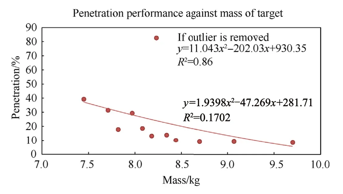
Fig.8.Penetration mitigation performance against mass of multi-layered targets when subject to high velocity impact loading from a solid steel projectile.
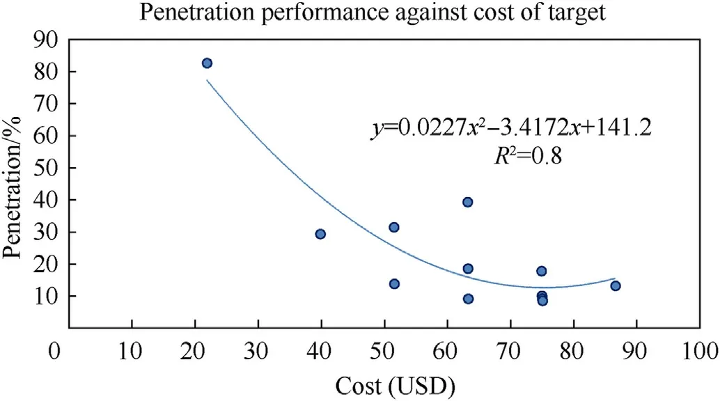
Fig.9.Penetration mitigation performance against cost of multi-layered targets when subject to high velocity impact loading from a solid steel projectile.
In all,these two polynomial relationships can be used to determine the required mass or cost for a pre-determined penetration performance,or vice versa.
3.3. Experimental validation of simulations
Lab scale experiments were carried out to validate the numerical simulations.The different layers of the protection system were clamped together using tape to closely replicate the model setup.Chemical bonding was not preferred to avoid the addition of an interface between materials.As mentioned in subsection 2.6,the validation was carried out using a scaled down setup due to limiting external factors.At lower impact velocities,the projectile was overmatched by the target.The largest penetration was observed in the lowest mass configuration (12.2% penetration).As predicted in the modelling,configuration 2H (best protection configuration) had the least penetration (5.7% penetration).
While the kinetic energy: target mass ratio has been kept constant,the amount of work being done by the target material during the time frame of the impact event is lower.This results in lesser energy being absorbed and dissipated by the target material,thus causing the lower deformation of the target[48].Fig.10 shows the individual layers of the target after it has been subjected to low velocity impact.
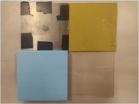
Fig.10.Individual layers of the protection system (Configuration 2H) after it was impacted by a steel projectile (5 mm diameter) at 400 m/s.Starting from the top left:Aluminium plate (top left),Kevlar-epoxy plate (top right),polyurethane foam layer(lower left),polycarbonate layer (lower right).
From the figure,it can be noted that the aluminium layer undergoes maximum deformation while the remaining layers are not visibly affected.This further supports the qualitative observations from the simulations that the target overmatches the projectiles at a lower velocity due to lesser work being done by the target material during the impact event.While the low velocity (400 m/s)impact scenario isn’t an accurate representation of the impact at higher velocities (1500 m/s),it provides a secondary validation of the material models used in the earlier simulations.
3.4. Effect of projectile size
While the optimal configuration proposed was obtained using the given scenario outlined within this manuscript,its effectiveness against threat variation is unclear.The threat was varied by increasing the radius(and consequently the mass)of the projectile.To keep a common denominator for measuring system performance,the kinetic energy density(KED)of the projectile was kept the same as the case(s)with projectile radius 2.47 mm.The radius of the projectile for the additional test was 5 mm and the subsequent mass was 4.13 g.The constant KED value for this test was 1.102×10⁷J/m2.For the additional test,this value was achieved by reducing the velocity of the heavier projectile to 915.2 m/s.Fig.11 shows the setup for the additional test.
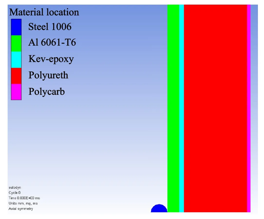
Fig.11.Setup of additional test with 5 mm radius fragment and velocity 915.2 m/s with constant KED.
It was observed that the larger projectile easily perforates the protection system even with a relatively lower velocity.While the KED of the projectile is unchanged,the larger mass increases its kinetic energy.The kinetic energy of the 0.5 g projectile was 422.5 J whereas the 4.Projectile had a kinetic energy of 1731.24 J.The value of kinetic energy is important because the transfer of energy from the projectile to the protection system allows it to deform and dissipate the transferred energy [48].In the additional test,a significantly higher amount of kinetic energy was transferred to the system over the same time scale when compared to the tests with the smaller projectile.The larger energy transfer resulted in the larger deformation and subsequent failure of the protection system.Therefore,this additional test shows that a good configuration needs to consider multiple threat scenarios in view of evolving threats.However,over-engineering the protection system may lead to higher cost and mass as seen from the example in.Table 11 Despite this,maintaining the same level of protection may also bring about risks that need to be identified and balanced against.In addition,besides performance,mass,and cost,there also exists other requirements that may affect the decision as well.
4.Conclusions
The aim of balancing penetration mitigation performance,mass and cost of a protective target system is achieved as an optimal configuration is numerically simulated.In this study,monolithic targets were investigated first followed by multi-layered targets.It was concluded that the multi-layered target system provides a more balanced solution,without having large penalties on mass and cost.The multi-layered target (AL-KE-PU-PC) consists of (1)impeding layer (Al 6061),(2) the wave spreading layer (Kevlar®epoxy),(3) the porous layer (PU foam) and (4) the support layer(polycarbonate),each with different functions to provide mitigation against penetration.
ANSYS AUTODYN® 2D was set up and used to simulate twelve multi-layered targets configurations of 280 mm radius and 50 mm total thickness,to obtain the penetration mitigation performance.Most material data were obtained from AUTODYN® library except for the PU foam which required the use of a P-α model.The results were analysed to select configurations based on lowest cost,lowest mass,best performance,and optimal configuration simultaneously balancing these three parameters mentioned.The optimal configuration has layers with thickness of 7,3,38,2 mm respectively with a total mass of 7.97 kg,total cost of $39.86 and penetration of 29.34%(14.67 mm)by a steel fragment of 2.47 mm radius with high velocity of 1319.26 m/s.Polynomial relationships between performance and mass/cost are also determined.
Since the proposed solution is optimised for the specific threat of such fragment,further test was conducted using a fragment of larger mass(with constant KED)to validate the target performance on another scenario.The result show that in this case,the target system is perforated by the fragment with residual velocity of 470 m/s.
In conclusion,this shows that the design solution needs to consider the evolving threat scenario and over-engineered the solution,while maintaining minimal cost and mass of the system.However,the approach used in this study can thus be replicated to determine the optimal solution balancing penetration mitigation.Performance,mass,and cost for a specific threat scenario.
Declaration of competing interest
The authors declare that they have no known competing financial interests or personal relationships that could have appeared to influence the work reported in this paper.
Appendix A.Supplementary data
Supplementary data to this article can be found online at https://doi.org/10.1016/j.dt.2023.01.013.
杂志排行
Defence Technology的其它文章
- High-Velocity Projectile Impact Behaviour of Friction Stir Welded AA7075 Thick Plates
- Influence of liquid bridge force on physical stability during fuel storage and transportation
- Adaptive fuze-warhead coordination method based on BP artificial neural network
- Investigation on the ballistic performance of the aluminum matrix composite armor with ceramic balls reinforcement under high velocity impact
- Dynamic analysis of buried pipeline with and without barrier system subjected to underground detonation
- AI-based small arms firing skill evaluation system in the military domain
