Drop weight impact analysis of GFRP tubes with hollow glass particlefilled matrix
2023-12-07DnielPulVelmurugnGupt
Dniel Pul ,R.Velmurugn ,* ,N.K.Gupt
a Department of Aerospace Engineering, Indian Institute of Technology Madras, Chennai, India
b Department of Applied Mechanics, Indian Institute of Technology Delhi, New Delhi, India
Keywords: Composite tubes Syntactic foam Impact Axial compression Digital image correlation
ABSTRACT Protecting occupants or payloads in crashes and blasts is of utmost importance in both moving and immobile structures.One way of achieving this is by using a sacrificial energy absorber.Composite tubes have been studied as potential energy absorbers due to their ability to fail progressively under axial compression.In this study,the energy absorption capability of these tubes is enhanced by adding hollow glass particles to the matrix.Drop-weight tests are performed on composite tubes,and a digital image correlation (DIC)-based technique is used to capture their load-displacement behaviour.This eliminates the use of electronic data acquisition systems,load cells,and accelerometers.The load-displacement curves of the tubes are obtained from the DIC-based technique and examined to understand their crushing behaviour.Although the mean crush load shows a drop,an increase in crush length is noticed.The specific energy absorbed by the tubes improves with an increase in GMB volume fraction.The addition of 0.1,0.2,0.3 and 0.4 vol fractions of GMB results in the specific energy absorption increasing by 6.6%,14.7%,24% and 36.6%,respectively,compared to neat glass fibre-epoxy tubes.Visual examination of the tubes and comparison with tubes subject to quasi-static compression is also performed.
1.Introduction
In most accidents or disasters,the phenomenon of impact,in one form or the other,generally causes the maximum damage.Protecting lives is the main priority in moving objects,such as vehicles that carry humans,and in stationary structures,such as buildings.In most cases,this protection is provided at the cost of a part of the structure.This part may absorb the impact energy imparted to the entire structure by deforming itself plastically or by other energy-absorbing mechanisms.These are called collapsible or sacrificial energy absorbers.A thorough review of such energyabsorbing structures is given by Alghamdi [1].Elements of different shapes,such as tubes,frusta,and sandwich structures,are studied.Tubes have been used widely for this purpose as they are the commonly used structural members.Lateral compression of metal tubes has been studied by Gupta et al.[2],while Reid [3]investigated the failure modes during axial compression of seamless mild steel tubes.Axial compression of tubes ensured a steady,progressive failure due to axial buckling,external wall inversion,and axial splitting.Despite its availability and ease of manufacturing,metals are heavy and not suitable for marine,aerospace,and defence applications where weight saving is of extreme importance.The increase in the use of composites has made them a substitute material for these metal energy absorbers due to their light weight and high strength.
The axial crushing behaviour of polymer-based fibre-reinforced tubes has been studied since the 1980s[4,5].Composite tubes also exhibit progressive crushing,but the modes of energy absorption and failure are very different from those of metal tubes.The application of composite tubes to protect civil engineering structures from the effect of blasts has been discussed by Van Paepegem et al.[6].Several studies have been carried out on the quasi-static compression of composite tubes to understand the failure mechanics.The progressive crushing mechanism of such tubes has been described by Hull[7].Unlike metals which deform plastically,composite tubes deform progressively by the mechanism of petal formation.In this process,the fibre layers in the laminated composite delaminate and splay inwards and outwards.This leads to axial splitting of the splayed walls,which leads to the formation of petals inside and outside the tube.Various fibres such as carbon,kevlar and glass have been studied and their respective failure mechanisms have been discussed [8].Different shapes of tubes have also been proposed and analysed.Mamalis et al.[9]have studied the crushing of square tubes reinforced with carbon fibre.The modes of failure of the tubes are found to be strongly dependent on the geometry of the tube and the materials used.Longer tubes result in global buckling and some tubes fail catastrophically.Palanivelu et al.[10]report that glass-polyester tubes of varying shapes with a thickness-to-diameter (t/d) ratio of less than 0.015 fail catastrophically,while the tubes fail progressively when this ratio is between 0.015 and 0.25.Modifying the tube edge to initiate petal formation is also done in most cases.This reduces the chances of catastrophic failure of the tubes.Chamfering of the tube end at a predetermined angle is one of the widely used trigger mechanisms.Other shapes,such as a tulip-shaped end,have also been studied[10].Numerical studies on the behaviour of corrugated tubes subject to axial impact have also been performed in prior Refs.[11,12].These show that the geometry of the tube plays an important role in the damage mechanisms and the energy absorption capability of the tubes.Studies on tubes with circular and square cross-sections generally conclude that circular tubes show better energy absorption [10,13,14].
Although several studies have been performed to investigate the crush properties of composite tubes under quasi-static conditions to understand the various failure modes involved,very few studies have been performed on the tubes subjected to impact loading.Palanivelu et al.[15]performed drop weight tests on pultruded glass fibre-polyester/vinyl ester tubes from varying heights.The tubes were either chamfered or cut in a tulip shape at the impacting end.Square and circular tubes were tested,and the circular tubes with chamfered ends were found to have the best energyabsorbing capacity.The load-displacement plots of the tubes are obtained using digital image correlation (DIC) techniques using a high-speed camera which records the impact event [16].This is a better method of data acquisition compared to using load cells,accelerometers,and the electronic data acquisition system.
Attempts to improve the energy absorption capabilities of composite tubes have been undertaken in the past.Studies such as stitching of the fabrics [17,18]and filling the tubes with polymeric foams[19]have been tried in order to improve their performance.While stitching increases the weight of the tubes,filling the tubes with a filler prevents petal formation,which is the mechanism which causes progressive failure.Bio-inspired bi-tubular structures have been proposed in Refs.[14,20,21]to improve energy absorption characteristics.Including a foam in the region between the two walls in a bi-tubular structure has also been studied by Goel [13]and Yang et al.[22].To achieve the required crush properties while maintaining lower weights,tubes fabricated with glass fibre mats and glass microballoon (GMB)-filled epoxy matrix have been used in a previous study by the authors [23].Hollow particle-filled polymer systems,commonly known as syntactic foams,have been used in several applications where the basic requirement is less weight.These foams are very efficient in compression and their light weight enables them to have better specific properties(properties per unit weight)[24].The addition of GMB to the matrix of composite tubes is found to improve the mean crush load and energy absorption under compression.This is attributed to an improvement in the interlaminar shear strength and fracture toughness of the fibre-reinforced composites due to the addition of GMB.It has been shown that an increase in fracture toughness of a fibre-reinforced composite plate improves its resistance to crushing[25].It is also found that the addition of GMB is found to improve the crush properties in the hollow tubes.
In this study,drop weight impact tests are performed to investigate the performance of hollow composite tubes with the addition of hollow glass particles.The tubes are fabricated with glass fibre mats and epoxy.Chamfering of the impacting end is done to promote petal formation and ensure progressive failure.A digital image correlation(DIC)-based technique is used to acquire the data during the test from which the load-displacement curves are extracted.The effect of the addition of glass particles and other geometric effects are studied.
2.Fabrication of the samples
2.1. Material used
The material used for the fabrication of the composite tubes are as follows:
· Araldite LY556: Bisphenol A diglycidyl ether (DGEBA)-based epoxy resin
· Aradur HY951: Triethylenetetramine (TETA)-based hardener
· Bidirectional woven glass fibre mats having an areal density of 600 gsm (grams per square metre)
· K15-type glass microballoons (GMB): hollow glass particles procured from 3 M Corporation having a mean diameter of 70 μ m,average wall thickness of 0.7 μ m and a typical true density of 0.15 g/cm3[26].A photograph and a micrograph showing the GMB used are shown in Fig.1.

Fig.1.(a) Photograph;(b) Scanning electron microscope image of the glass microballoons used.
2.2. Fabrication process
Composite tubes are fabricated by winding a fibre mat over a mandrel and applying the resin with GMB included.A predetermined amount of glass microballoons are added to epoxy depending on the GMB volume fraction.This volume fraction is defined as the ratio of GMB to the weight of the matrix and filler(resin+GMB).The GMBs are dispersed in the resin by using a mechanical stirrer.The glass fibre mats are cut to the required lengths according to the number of layers needed in the tube.All the tubes fabricated for the current study are four-layered with an average wall thickness of 2.8 mm and an inner diameter of 36 mm.The weight fraction of the fibre to the matrix is taken as 0.5.The hardener is added to the resin-GMB mixture and stirred properly.The fibre mat is wound around a cylindrical mandrel whose diameter is equal to the required inner diameter of the tubes.The mandrel is held on a device which rotates it axially.The resin mixture is poured onto the mat and allowed to wet the mat completely with a roller.Once the entire mat is wound,a plastic sheet is wound over it and the mandrel is allowed to rotate until the resin cures.The rotation ensures that the resin does not collect on one side of the tube and that the tube thickness is constant throughout.After the composite tubes were allowed to cure for 24 h,the tube is extracted from the mandrel and cut into samples of length 72 mm which corresponds to a length-to-diameter ratio of 2.The samples of varying GMB volume fractions are shown in Fig.2.One end of the tube is chamfered to an angle of 45°to promote progressive failure of the tubes.An image showing the chamfered end of the tube is given in Fig.3.

Fig.2.Composite tubes fabricated for impact tests.
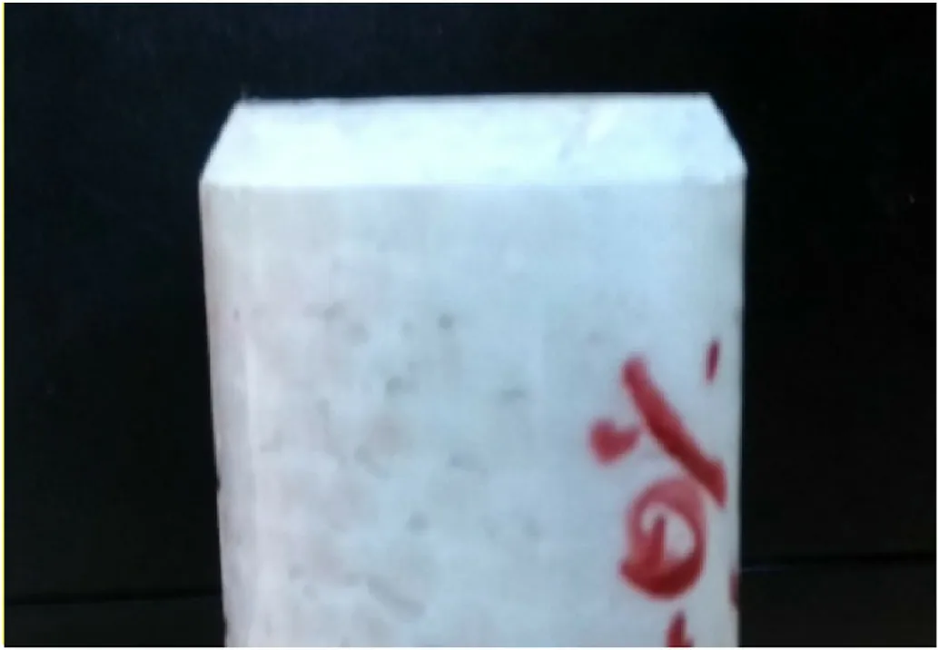
Fig.3.A photograph of the chamfered end of the tube.The angle of chamfer is 45°.
3.Experimental studies
3.1. Test methods
The impact tests are carried out on an in-house fabricated drop weight setup which is shown in Fig.4.The maximum height of drop is 1.5 m.The impactor has a flat base and its weight can be varied by adding or removing weights.The samples are placed on a metallic bed and the impactor is lifted to a predetermined height using a 12 V DC electromagnetic lift and dropped.Image processing-based technique is used for data analysis.The front face of the impactor has a speckle pattern.The image of the speckle pattern on the impactor before contact with the sample is shown in Fig.5.The impact event is recorded using a high-speed camera.The Phantom V511,which can record up to 30,000 frames per second (fps),is used for this purpose.The recorded frames are then analysed using the digital image correlation(DIC)software,VIC-2D.In general,the purpose of the speckle pattern is to enable the (DIC) software to track and measure the deformation and strains developed in the area of interest.However,in the current study,the measurement of interest is the quasi-rigid displacement of the metal impactor.Thus,the speckle pattern is analysed using the software to obtain the impactor displacement as it comes into contact with the specimen.As the specimen gets crushed,the impactor decelerates and this is captured in a displacement-time plot.The velocity and acceleration plots are obtained by numerical differentiation.A second-order central difference approximation is used (Fig.6).Ifs1,s2,…,siare the displacement values at time instantst1,t2,…,ti,then the velocityviand accelerationaiare given as

Fig.4.The drop-weight setup.
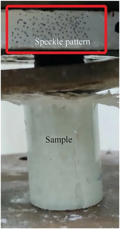
Fig.5.The speckle pattern on the impactor.

Fig.6.A visual representation of the terms involved in the second-order central difference approximation.
where Δtis the time step between any two instants.Finite differences provide a good way to approximate a derivative.The secondorder differences give better approximations.
Differentiation of the displacement values using numerical methods induces noise in the velocity plots.The data is smoothed by using the spline curve fitting option in MATLAB.The spline is useful in situations where a curve cannot be represented by a single polynomial.It is essentially a piecewise polynomial function which provides a smoother fit.It fits a few data points with a polynomial fit and continues this for the entire curve.This gives a smooth velocity plot which can be further differentiated to obtain the acceleration data.The load (Pi) is calculated from the acceleration as
wheremis the impactor mass.From these values,the loaddisplacement curves are plotted.These curves provide information on various crush parameters,which are described below.
·Peak crush load:The maximum load the composite tube can withstand under axial compression.
·Mean crush load:The mean load experienced by the composite tube as it undergoes crushing.It is calculated using the expression.
wherenis the number of time steps analysed,Piis the load at theith instant,(li-li-1)is the crush length between instantsi-1 andi,andlmaxis the maximum crush length of the tube.
·Crush force efficiency:The ratio of the mean crush load to the peak crush load.
·Energy absorbed:The energy absorbed by the sample is measured from the area under the load-displacement plots obtained from experiments.
·Specific energy absorbed:This is the ratio of the energy absorbed to the corresponding weight of the sample.
3.2. Results and discussion
Drop weight tests of the samples with varying GMB volume fractions are performed using a drop mass weighing 35 kg from heights of 0.5,1 and 1.5 m.A photograph of one of the failed samples impacted from a height of 1 m is shown in Fig.7(a).Prominent petal formation is seen in all the samples.This is due to the chamfering of the tube end coming into contact with the impactor,which ensures progressive failure.The failure of the tubes begins at the chamfered end subject to impact and gradually propagates until the entire impacting energy of the impactor has been absorbed.In the absence of a chamfered end,the tubes will fail catastrophically at a point in the tube wall which reaches a critical stress value.

Fig.7.(a) Top view of a compressed composite tube due to impact;(b) Top view of a compressed composite tube due to quasi-static loading [23].
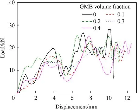
Fig.8.Load-displacement plots of samples with varying GMB volume fractions impacted from a height of 0.5 m.
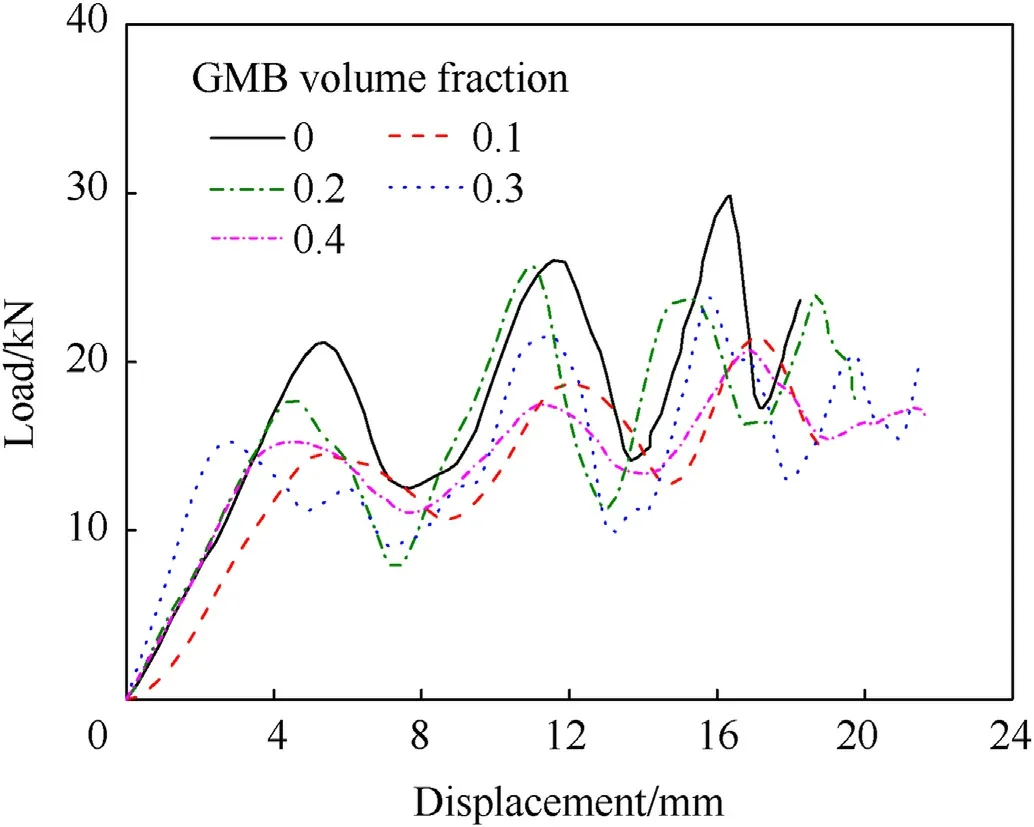
Fig.9.Load-displacement plots of samples with varying GMB volume fractions impacted from a height of 1 m.
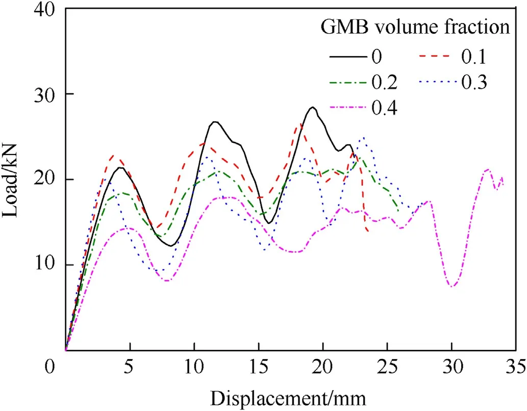
Fig.10.Load-displacement plots of samples with varying GMB volume fractions impacted from a height of 1.5 m.
The kinetic energy of the impacting plate is absorbed by the tubes due to the various deformation phenomena which occur during the crushing.The major energy-absorbing modes are
(1) Energy absorbed by delamination.
(2) Energy absorbed by axial cracking.
(3) Energy absorbed by bending of the petals.
(4) Energy absorbed by interlaminar shear deformation in the petals during bending.
(5) Energy dissipated by friction between the petals and the loading plates.
Fig.7(b) shows the top view of a tube subjected to quasi-static compression on a universal testing machine at a crosshead speed of 2 mm/min [23].On visually comparing the samples due to impact loading (Fig.7(a)) with tubes crushed by quasi-static compression,it is seen that the tubes crushed by impact show a larger extent of cracking in the longitudinal direction.The extent of petal bending is lower and distinct petals are not seen.The matrix is seen to have been damaged in a more brittle fashion.This might be due to the impact event taking place in a very short duration compared to a quasi-static loading.Glass fibre-reinforced epoxy composites show considerable strain-rate effects with their dynamic strengths considerably higher than their quasi-static properties[27].This leads to the conclusion that the dominant property in tubes subject to impact is the tensile strength of the composite wall,while the tubes subjected to quasi-static compression are mainly influenced by the interlaminar properties of the composite.The addition of GMB to GFRP composites is found to improve the interlaminar properties while the tensile and flexural properties decrease[23].This effect,coupled with the brittle failure of epoxybased composites at higher strain rates,is the reason for a larger extent of longitudinal cracking in tubes subject to impact compared to those crushed quasi-statically.
After the post-processing of the images captured by the highspeed camera,the load-displacement plots are obtained for the samples.The plots for the samples with varying GMB volume fractions are presented in Figs.8-10.These figures are for the tubes of varying GMB volume fractions impacted from heights of 0.5,1 and 1.5 m,respectively.All the plots show an initial linear region which represents the elastic deformation of the tube with the initial peak being less than the other peaks due to the crushing of the initial chamfered portion of the tubes.The region after this shows a plateau region where the load oscillates around a mean crush load.This is caused by the phenomenon of petal formation in the tubes.These regions are not so distinct in Fig.6 since the crush length is very small for samples impacted from 0.5 m.
The extent of crushing and the mean crush load are both indicators of the energy absorption of the tubes.To be used as energyabsorbing structures,the tubes should be crushed at a desirable load but fail progressively up to a large extent so that they can absorb maximum energy from the impact loading.The crush parameters obtained from the experiments are tabulated in Table 1.The kinetic energy on impact for the 0.5,1 and 1.5 m drops are approximately 157,314 and 471 J,respectively.For all the cases,the specific energy absorption increases with an increase in GMB volume fraction.The specific energy absorbed by the various tested tubes is shown graphically in Fig.11.Unlike quasi-static compression,where all the tubes were compressed up to a predetermined displacement such that the energy input is the same for all cases,the amount of crushing of the tubes under drop-weight impact varies in proportion to the resistance offered by the samples.The variation of the maximum crush lengths of the samples is shown in Fig.12.The maximum crush length is calculated from the displacement data for each sample obtained from the DIC software.It is found that samples with a higher proportion of GMB get crushed to a larger extent,the maximum being the 0.4 vol fraction samples impacted from a height of 1.5 m which get crushed to around 34 mm.A photograph of the pure GFRP tubes impacted from varying heights is shown in Fig.13.This causes the specific energy absorption to increase with the addition of GMB,even though the mean crush load drops.The mean crush loads of the samples tested are compared graphically in Fig.14.The drop in mean load upon the addition of GMB could be attributed to the fact that cracking of the tube walls is seen to be the dominating failure mode.This depends largely on the tensile strength of the tube material.The tensile properties of GFRP composites tend to drop upon the addition of GMB due to improper bonding between the GMB and epoxy.This causes more cracks in the petals when compared to tubes compressed quasi-statically.Another observation from Fig.14 is that the strain rate effect is more prominent in samples with lower GMB volume fractions.This may be attributed to the fact that epoxy is significantly more dependent on strain rate than the glass particles among the two constituents of the matrix[28].Higher GMB volume fractions mean a lower epoxy volume which could be the reason for this effect.

Table 1 Crush parameters obtained from experiments (SEA=Specific Energy Absorbed).
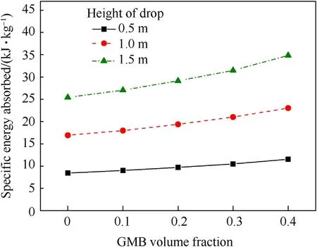
Fig.11.Variation of the specific energy absorbed by the samples with varying GMB volume fractions for weights dropped from different heights.
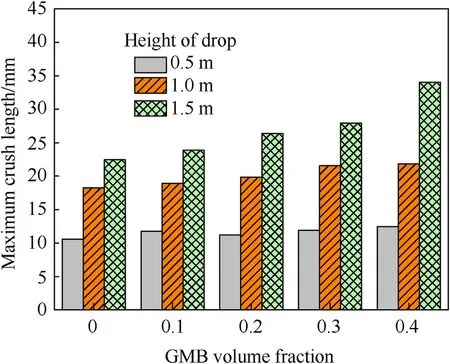
Fig.12.Variation of the maximum crush length of the samples with varying GMB volume fractions for weights dropped from different heights.

Fig.13.Pure GFRP tubes after impact from varying heights (0.5,1 and 1.5 m from left to right).
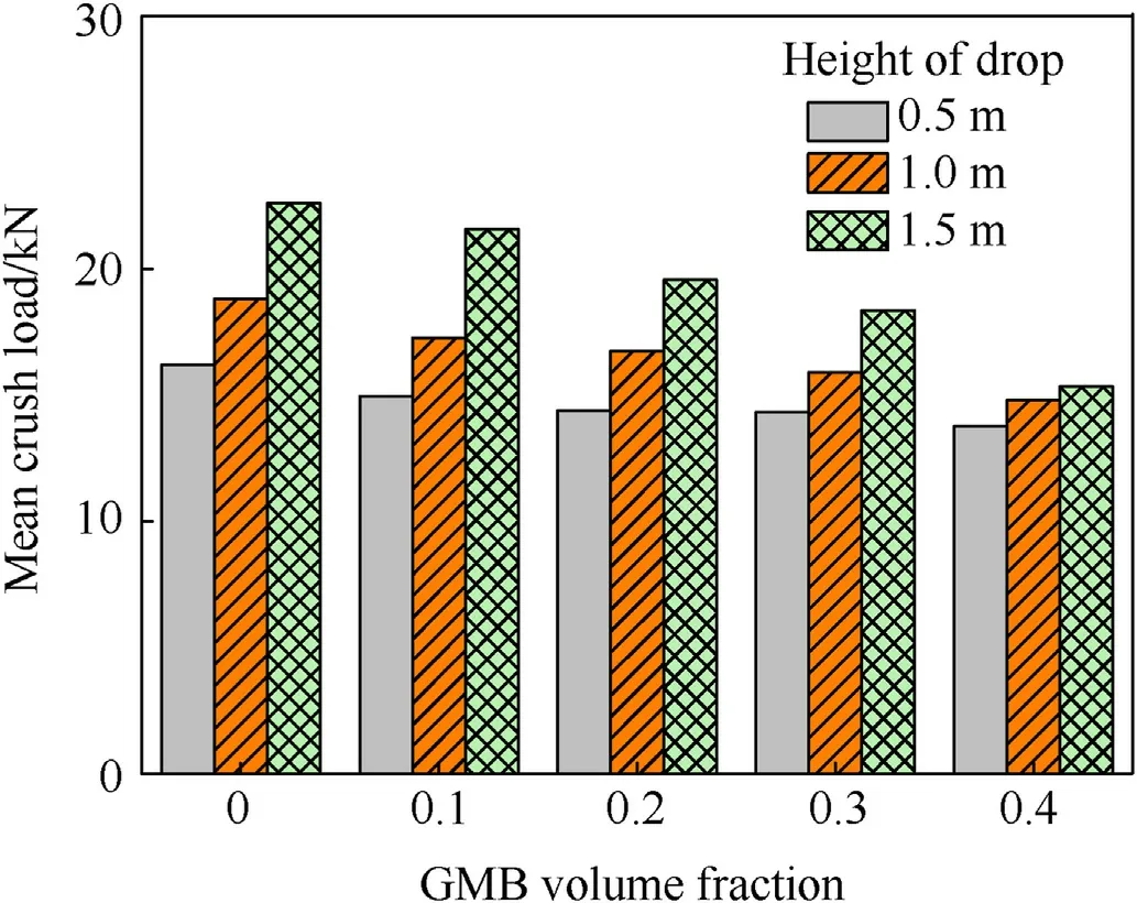
Fig.14.Variation of the mean crush load of the samples with varying GMB volume fractions with weights dropped from different heights.
The values of mean crush load upon the addition of GMB to the composite tubes subject to impact loads are compared to the corresponding values in tubes compressed quasi-statically and are given in Fig.15.The quasi-static data is obtained from an earlier work by the authors [23].It can be seen that the mean crush load decreases in tubes subject to impact while it increases under quasistatic loading.Visual examination shows that tubes subject to impact (Fig.7(a)) undergo more damage by axial cracking,which depends on the tensile strength of the tube wall.GMB-filled epoxy has lower tensile properties even though the weight reduction causes the specific properties to rise.On the other hand,quasistatic compression of these tubes results in neat petal formation and splaying of the wall (Fig.7(b)),which depend on the interlaminar properties.The addition of GMB to fibre-reinforced epoxy is found to improve its interlaminar properties [29].The mean crush load of tubes under impact can be thus improved by enhancing their tensile properties.This can be done by either using stronger microballoons or by improving the GMB-epoxy bonding.

Fig.15.Comparison of the mean crush load variations of tubes crushed by quasi-static and impact loads.
Fig.16 compares the specific energy absorption values obtained in the drop weight tests to those obtained for the corresponding GMB volume fractions in quasi-static tests.The values are tabulated in Table 1.Since the quasi-static tests were displacementcontrolled,all the samples were subject to the same crush length of 50 mm,and the load-displacement behaviour was analysed.On the other hand,the crush length in the drop weight tests varies for each sample and depends on the weight of the impactor,the height of drop,and the sample properties.To aid in comparison,quasistatic specific energy absorption values equivalent to each drop weight test are found according to Eq.(5).These values are compared to the drop weight results.

Fig.16.Comparison of the specific energy absorptions of tubes crushed by quasi-static and impact loads.The prefix QS denotes the quasi-static equivalent of the corresponding impact test.
In Fig.16,the first set labelled QS depict the specific energy absorbed by samples subject to a quasi-static compression up to 50 mm.QS 3.13,QS 4.43,and QS 5.42 denote the equivalent quasistatic values corresponding to the drop weight samples subject to impact velocities of 3.13,4.43 and 5.42 m/s,respectively.It can be seen that the samples subject to impact absorb more energy than the corresponding samples compressed quasi-statically for equal crush lengths.This difference is seen to increase with increasing velocity of impact.
4.Conclusions
The impact properties of composite tubes with GMB-filled matrix subjected to axial compression are investigated in this study.A drop weight setup is used to obtain the crush parameters experimentally.A DIC-based technique is adopted to acquire the data instead of using sensors and an electronic acquisition system which reduces the complexity of the setup.The effect of GMB volume fraction on the crush properties is studied.It is found that the addition of GMB to GFRP tubes increases their specific energy absorption.The mean crush load is found to drop,which is caused by lower tensile properties of GMB-filled fibre composites as the tubes subjected to impact show lower petal bending and more extensive axial cracking compared to samples crushed quasistatically.Axial cracking depends mainly on tensile properties.The weights of samples with GMB volume fractions of 0.1,0.2,0.3,and 0.4 reduce by 6.2%,12.7%,19.6%,and 26.9%,respectively.This weight reduction is a major advantage of these particle-filled tubes,making them useful in several applications.
Declaration of competing interest
The authors declare that they have no known competing financial interests or personal relationships that could have appeared to influence the work reported in this paper.
Acknowledgements
This study is supported by the Department of Science and Technology (DST,India) through the Indo-Russian collaborative project scheme.
杂志排行
Defence Technology的其它文章
- High-Velocity Projectile Impact Behaviour of Friction Stir Welded AA7075 Thick Plates
- Influence of liquid bridge force on physical stability during fuel storage and transportation
- Adaptive fuze-warhead coordination method based on BP artificial neural network
- Investigation on the ballistic performance of the aluminum matrix composite armor with ceramic balls reinforcement under high velocity impact
- Dynamic analysis of buried pipeline with and without barrier system subjected to underground detonation
- AI-based small arms firing skill evaluation system in the military domain
