Effect of Weft Binding Structure on Compression Properties of Three-Dimensional Woven Spacer Fabrics and Composites
2023-10-29LIUShengjie刘生杰JIANGFeiZENGJinjin曾金金SHAOHuiqi邵慧奇JIANGJinhua蒋金华CHENNanliang陈南梁
LIU Shengjie(刘生杰), JIANG Fei(江 飞), ZENG Jinjin(曾金金), 3, SHAO Huiqi(邵慧奇), 4, JIANG Jinhua(蒋金华)*, CHEN Nanliang(陈南梁)
1 Shanghai Frontier Science Research Center for Modern Textiles, College of Textiles, Donghua University, Shanghai 201620, China 2 Changzhou Saijia Machinery Co., Ltd., Changzhou 213132, China 3 Shanghai Composite Technology Co. Ltd., Shanghai 201620, China 4 Innovation Center for Textile Science and Technology, Donghua University, Shanghai 201620, China
Abstract:With the wide use of three-dimensional woven spacer composites(3DWSCs), the market expects greater mechanical properties from this material. By changing the weft fastening method of the traditional I-shape pile yarns, we designed three-dimensional woven spacer fabrics (3DWSFs) and 3DWSCs with the weft V-shape to improve the compression performance of traditional 3DWSFs. The effects of weft binding structures, V-pile densities, and V-shaped angle were investigated in this paper. It is found that the compression resistance of 3DWSFs with the weft V-shape is improved compared to that with the weft I-shape, the fabric height recovery rate is as high as 95.7%, and the average elastic recovery rate is 59.39%. When the interlayer pile yarn density is the same, the weft V-shaped and weft I-shaped 3DWSCs have similar flatwise pressure and edgewise pressure performance. The compression properties of the composite improve as the density of the V-pile yarns increases. The flatwise compression load decreases as the V-shaped angle decreases. When the V-shaped angle is 28° and 42°, the latitudinal V-shaped 3DWSCs perform exceptionally well in terms of anti-compression cushioning. The V-shaped weft binding method offers a novel approach to structural design of 3DWSCs.
Key words:weft V-shaped binding; three-dimensional woven spacer fabric(3DWSF); compression property; pile yarn density; V-shaped angle
0 Introduction
Three-dimensional woven spacer composites (3DWSCs) are a new generation of composites developed to overcome the challenges faced by traditional composites. They are widely used not only in military applications such as aerospace, but also in civil applications such as rail, home construction and automotive interiors due to one-piece weaving, light weight and designability[1-3]. As an excellent fiber structure reinforcement, the three-dimensional woven spacer fabric(3DWSF) is gradually replacing 2D metal-based plywood and honeycomb sandwich structures[4]. The rapid development in related fields is also increasing the demand for woven spacer structures which can improve mechanical properties and also are light in weight.
The 3DWSF has the characteristics of integrity and hollowness. Pile yarns pass through the upper and the lower layers of the fabric, forming a continuous 3D structure. Different types of pile yarns and different consolidation methods can be selected for the hollow spacer filaments to meet different performance requirements[5-7]. Therefore, changes in the structure and the material of the pile yarns can effectively improve the mechanical properties and dimensional stability of the reinforcement.
From the viewpoint of industrial production, it is found that the traditional weft I-shaped 3DWSF has obvious defects[8]. In the process of production, transportation and processing, the surface layer of the fabric is squeezed by an axial force, the spacer piles fall to one side and the angle between the piles and the surface layer is close to 0°, causing the upper layer and the lower layer to stick together[9]. After the external force is removed, the pile yarns cannot return to the original state, which directly decreases to the fabric thickness, and affects the thickness of the finished composite[10-11]. Therefore, most of the traditional weft I-shaped 3DWSFs require a secondary allowance in the thickness direction and a thickening of the layering[12], which increases the labor cost of additional manual work.
Kambledetal.[13]designed and manufactured four types of 3DWSFs with varied shapes. One of these is the V-shaped structure, and it is made up of interconnected layers of single fabrics that form shaped channels in the weft section.
In this paper, two types of 3DWSFs, namely weft I-shaped and weft V-shaped, have been designed and produced with reference to the traditional 3DWSFs. The innovation of the weft V-shaped fabric designed in this paper is that the V-shape constructed by the spacer layers is formed by a single pile warp yarn passing through upper and lower layers of the fabric. This design makes the fabric fluffier, lighter and more resistant to deformation. The study focuses on the compression resistance of two different weft-binding 3DWSFs, the flatwise/edgewise compression properties and damage modes of spacer composites. The effects of the weft consolidation method, V-angle and pile density on the compression properties of spacer fabrics and composites are investigated.
1 Experiments
1.1 Materials, equipment and specimens
E-glass fibers were supplied by China Jushi Co., Ltd. (Tongxiang, China). MGS RIMR 035C epoxy resin and 037C curing agent were provided by Westlake Management(Shanghai, China)Co., Ltd.. Additional equipment includes an MTS electronic universal testing machine, a vacuum oven, vacuum pumps, high definition cameras,etc. The specimens include weft I-shaped with single-pile yarn fabrics(WISS-3DWSFs), weft V-shaped with single-pile yarn fabrics(WVSS-3DWSFs), and weft V-shaped with double-pile yarn fabrics(WVSD-3DWSFs). The V-shaped angle of the WVSS-3DWSFs was 15°, 22°, 28°, and 42°, and the corresponding composites were named as WVSS-VA15, WVSS-VA22, WVSS-VA28, and WVSS-VA42. Detailed weaving yarn parameters of 3DWSFs are shown in Table 1.

Table 1 Specific weaving yarn parameters of 3DWSFs
1.2 Design of 3DWSFs
As shown in Figs.1 and 2, WISS-3DWSFs and WVSS-3DWSFs were designed by changing the solidification of the weft pile yarns of the 3DWSFs. It could be seen from Figs.1(a) and 2(a) that the face sheets were woven in the plain weave and the fancy rib weave. The pile yarns passing through the upper and lower sheets of the fabric, forming a continuous three dimensional(3D) structure. Figures 1(b) and 2(b) demonstrate explicitly two different weft binding methods. Figures 1(c) and 2(c) show the numbers of pile yarns within one weave repeat for two different fabrics.
1.3 Fabrication of 3DWSCs
MGS RIMR 035C epoxy resin and 037C curing agent were mixed at 25 ℃ at a mass ratio of 100∶28. Then, the mixture was penetrated into the fabric through the vacuum assisted resin infusion (VARI) process. The resin-impregnated fabric was put into the vacuum oven and dried at 50 ℃ for 5 h and then 80 ℃ for 8 h.
1.4 Compression performance test
The compression performance test of fabrics was conducted according to the standard GB/T 24442.2—2009. The specimen size was 50 mm × 50 mm and each sample was subjected to at least 10 reciprocal compression cycles. High response rates, compression work, recovery work, and elasticity rates were recorded. The flatwise compression test of composites was conducted by the MTS electronic universal testing machine (CMT Model E42, MTS Shanghai, China) according to the standard of GB/T 1453—2022 and the specimen size was 30 mm×30 mm. The edgewise compression test by the MTS electronic universal testing machine was conducted according to the standard of GB/T 1454—2022 and the the specimen size was 100 mm×30 mm.Five specimens were tested for each sample at a loading speed of 2 mm/min in both compression tests, and the average value was taken.
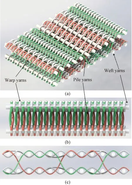
Fig.1 Structural diagrams of WISS-3DWSF: (a) main view; (b) weft direction view; (c) warp direction view
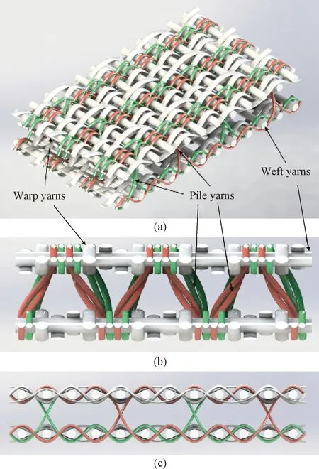
Fig.2 Structural diagrams of WVSS-3DWSF: (a) main view; (b) weft direction view; (c) warp direction view
2 Results and Discussion
2.1 Compress-resilience of weft I/V shaped 3D woven spacer fabrics
The changes in the pile yarn recovery pattern (Fig.3) and the fabric height recovery rate (Fig.4) when the axial force was released from the fabric within 1 000 ms were captured using a high-definition camera(MOKOSE, Shenzhen Yunlang Technology CO. LTD., China).
Figures 3(a) and 3(b) show the morphological changes of the height recovery process for two types of fabrics. Due to its own gravity and the impact of external compression factors, the WISS-3DWSF has a smaller angle between the spacer piles and the face layer, resulting in a lower height recovery rate.
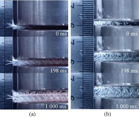
Fig.3 Diagram of recovery of pile yarn after compression: (a) WISS-3DWSF; (b) WVSS-3DWSF
However, owing to its distinctive V-shaped weft binding mechanism and the elasticity of the yarns, the WVSS-3DWSF retains its initial shape once the compression force is withdrawn. As shown in Fig.4, the WVSS-3DWSF completes the compression recovery process at 825 ms, while the height recovery was slow in the WISS-3DWSF. It could be found that the height recovery rate of the WVSS-3DWSF reaches 95.7%, while that of the WISS-3DWSFs is only 88.3%.

Fig.4 Height recovery rate-time curves of WVSS-3DWSF and WISS-3DWSF
After several cycles of compression tests on the WVSS-3DWSF and the WISS-3DWSF, it is found that the curve could be clearly divided into three stages[14-16]in the load-displacement curve of the WVSS-3DWSF shown in Fig.5.
The first stage is the linear elastic stage[14]. The V-shaped pile yarns have not yet produced a large deformation at the beginning of the force due to the stable triangular structure enclosed with the surface layer, and the pressure is effectively transmitted to the following layer through the V-shaped pile yarns, so the load increases approximately linearly. The second stage is called the smooth stage[15-16]. As the compression displacement increases, the V-shaped pile yarn deforms leading to the shortening of the effective length, and the pile yarn begins to flex and is affected by the combined effect of torsion, shear and rotational deformation. The third stage is the densification stage[17]. The pile yarn collapses and contacts each other, and the slope reaches its maximum value. In contrast to the WISS-3DWSF shown in Fig.5(a), the second stage clearly misses, which indicates that it is much less resistant to cushioning than the WVSS-3DWSF. Due to the obvious isotropic collapse phenomenon of the I-shaped pile yarns during compression, the transition from the linear elastic stage to the densification stage is straightforward.
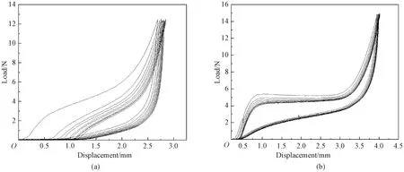
Fig.5 Load-displacement curves: (a) WISS-3DWSF; (b) WVSS-3DWSF
Compression performance test data are shown in Table 2. It can be seen that the average elastic recovery rate of the WVSS-3DWSF is 59.39%, which is about 1.5 times that of the WISS-3DWSF. At the beginning, the compression work of the WISS-3DWSF appeares a substantial decline. This is because when the WISS-3DWSF is pressed, the top and the lower fabric surface layers along the tilted direction of the pile yarns become misaligned, resulting in a less stable compression recovery performance than that of the WVSS-3DWSF. V-shaped pile yarns and upper and lower layers enclose a triangular structure. The triangular structure has a very uniform distribution of forces due to its particular shape, which allows it to withstand external pressures effectively and is not subject to local fatigue. When the three vertices of a triangle structure are compressed by an external force, the length of the fibers or yarns changes, which deforms the structure. The stresses are distributed relatively uniformly, allowing the structure to keep a stable shape and withstand fatigue. Moreover, the triangular structure has a high modulus of elasticity, which means that when an external force is applied, it deforms quickly and absorbs external energy before resuming its former shape.
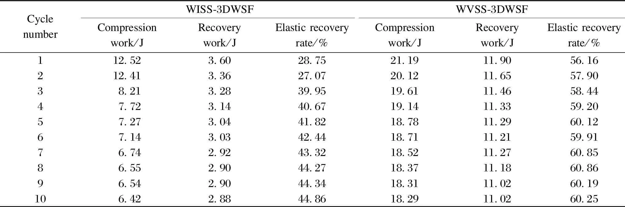
Table 2 Compression performance test data of WISS-3DWSF and WVSS-3DWSF
2.2 Compression strength of 3DWSCs
2.2.1Flatwisecompressionstrength
It can be seen from Figs.6(a) and 6(b) that the WISS-3DWSC shows fracture marks at the upper and lower ends of the I-shaped pile yarns in contact with the surface layer. Multiple pile yarns are wrapped and stuck together by resin into several thicker pile yarn bundles. It can also be observed from Figs.6(c) and 6(d) that the bottom ends of the pile yarns are clearly broken and misaligned.
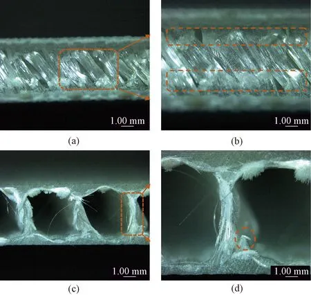
Fig.6 SEM images of WISS-3DWSC under flatwise compression: (a) partial picture in warp direction; (b) enlarged picture in warp direction; (c) partial picture in weft direction; (d) enlarged picture in weft direction
It can be seen from Figs.7(a) and 7(b) that both V-shaped pile yarns flex and break when they are subjected to the axial compression. Moreover, not only the joint point that is in contact with the face layer is broken by the force, but also a part of the pile yarns is stressed. Figures 7(c) and 7(d) show a schematic diagram in the warp direction, where the V-shaped pile yarns break more completely than the I-shaped pile yarns.
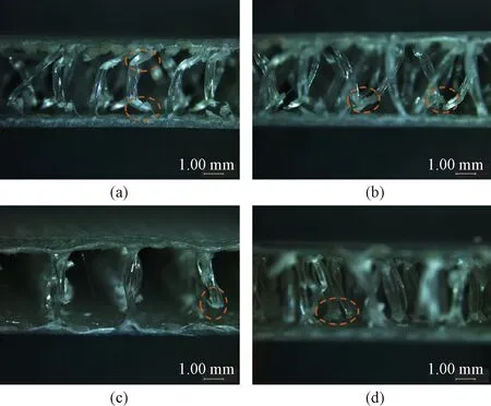
Fig.7 SEM images of WVSS-3DWSC under flatwise compression: (a) and (b) partial picture in weft direction; (c) and (d) partial picture in warp direction
Figure 8(a) illustrates the flatwise compression stress-strain curves. The compression strengths of the WISS-3DWSC and the WVSS-3DWSC are 2.65 MPa and 0.98 MPa, respectively. The main reason for the discrepancy is the difference in the pile density. As shown in Table 1, the pile density of the WISS-3DWSF is 2.3 times higher than that of the WVSS-3DWSF. If the density of the V-shaped pile yarn increases to the same value as that of the I-shaped pile yarn, we could predict that the compression strength of the two would be similar. This could also be proved from the histogram of the flatwise compression modulus as shown Fig.8(b). The difference between the two compression moduli is minimal.
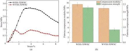
Fig.8 Flatwise compression properties: (a) flatwise compression stress-strain curves of WISS-3DWSC and WVSS-3DWSC; (b) histogram of flatwise compression modulus and strength
Both flatwise compression stress-strain curves approximately linearly increase in the initial phase and the deformation is elastic. After the curve of the WISS-3DWSC reaches the peak damage stress, the stress starts to decrease slowly due to the tipping and buckling of the I-shaped pile yarns. However, the WVSS-3DWSC exhibites a secondary peak damage. Since the yarns on one side of the V-shaped pile yarns are stressed initially, after one side of the pile yarns is damaged at the connection with the face sheets, the other side of the pile yarns continues to be stressed until the connection is damaged.
The characteristic of yarn breakage on both sides of the V-shaped pile yarns successively endows the WVSS-3DWSC with a longer buffer resistance time, which is an advantage over the traditional WISS-3DWSC.
2.2.2Edgewisecompressionstrength
As can be seen from Fig.9, the edgewise compression failure of the WVSS-3DWSC and the WISS-3DWSC occur mainly at the panels. However, there are discrepancies between the warp and the weft failure modes of the WISS-3DWSC and the WVSS-3DWSC.
In the warp direction of the WISS-3DWSC, the main edgewise compression damage is the sudden fracture of the panel. The thin crack is located between two rows of pile yarns on the pressed side, while there is a white trace on the stretched side, as shown in Fig.9(a). It indicates that the I-shaped pile yarns almost suffer no pressure[18]. In contrast, the edgewise compression damage in the weft direction is more drastic and pronounced. During the experiment, the specimen exhibited an instantaneous popping sound and rough cracks on both the pressed and the stretched side panels as shown in Fig.9(b).
The edgewise compression damage of the WVSS-3DWSC is quite similar in the warp and the weft directions. The major damage is manifested by the appearance of white dots and thin cracks in the panels as shown in Figs.9(c) and 9(d).
Firstly, the specimen flexed significantly during the test, but the panel did not fracture significantly. Secondly, the pile yarns at the flexion were squeezed. At the same time, the location of flexure was exactly the position of the white dots on the panel. For the WVSS-3DWSC, the panel and the V-shaped pile yarns jointly bore the pressure, and the V-shaped pile yarns could balance the force of the pressed panel and the stretched panel in the horizontal direction.
As shown in Fig.10(a), the edgewise compression load-displacement curve of the WISS-3DWSC in the warp direction reaches a peak and then fails abruptly, in which the decreasing trend is nearly a straight line. In contrast, the WVSS-3DWSC in the warp direction has no sudden failure, and the curve decreases slowly after reaching the peak load. The damage modes are not the same. The sudden drop of the edgewise pressure curve of the WISS-3DWSC is due to the panel fracture and the dislocation as shown in Fig.9(b), compared with the fracture failure of the V-shaped pile yarns at the flexure position of the WVSS-3DWSC, and there is no obvious damage of the panel as shown in Fig.9(d).
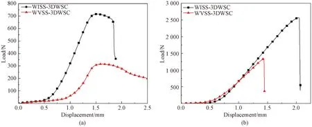
Fig.10 Edgewise compression load-displacement curves of WISS-3DWSCs and WVSS-3DWSCs: (a) warp direction; (b) weft direction
The peak edgewise load in the warp direction of the WISS-3DWSC is 715 N which is 2.3 times that of the WVSS-3DWSC. The peak edgewise load in the weft direction is 2 559 N which is 1.9 times that of the WVSS-3DWSC. Considering that the density of I-shaped pile yarns is 2.3 times that of the V-shaped pile yarns as shown in Table 1, it could be assumed that the peak edgewise load of the above two composites in both the warp and the weft directions is similar.
2.3 Compression strengths of WVSS-3DWSCs and WVSD-3DWSCs
When the WVSD-3DWSC is subjected to the flatwise compression, the damage pattern of the V-shaped pile yarns is similar to that of the I-shaped pile yarns in the WISS-3DWSC. Since the number of pile yarns forming the V-shaped structure is doubled while the resin encapsulates and cures the doubled pile yarns together, a V-shaped thick column is formed, which is similar to the I-shaped thick column formed in the WISS-3DWSC. From Fig.11, it could be seen that the V-shaped pile yarns collapse to one side in the warp direction. In the weft direction, breakage and misalignment occur at the connection between the V-shaped pile yarns and the panel.
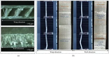
Fig.11 Flatwise and edgewise compression images of WVSD-3DWSC: (a)flatwise compression SEM images of WVSD-3DWSC; (b)edgewise compression failure images of WVSD-3DWSC
The main edgewise compression failure in the warp direction is shown in Fig.11(b). There is a sudden breakage of the panel with a rough crack located between the two rows of pile yarns on the compressed side and a white crease on the stretched side. The edge compression failure in the weft direction is more intense and visible with irregular cracks and large white marks in the panel. The surface density of the fabric panel increases as the V-shaped pile yarns double, resulting in fewer voids between yarns and the ability to withstand more loads.
The WVSD-3DWSC fails abruptly when the compression stress reaches the peak, as it is shown in Fig.12(a), and the decline reaches 57.6%. This phenomenon is absent in both the WISS-3DWSC and the WVSS-3DWSC, indicating that the WVSD-3DWSC is less resistant to flatwise compression cushioning than the other two. However the peak stress of the WVSD-3DWSC is 9.16 MPa, which is 3.5 times that of the WISS-3DWSC and 9.7 times that of WVSS-3DWSC. The V-shaped spacer pile yarns of the WVSD-3DWSC are fused together with the resin to form a number of integral V-shaped thick columns. This structure is similar to I-shaped pillars of the WISS-3DWSC, but the number of pile yarns wrapped in the thick pillar is twice that of the WVSS-3DWSC. The WVSD-3DWSC could bear larger flatwise compression loads as a result of this dual factors. Figure 11(a) shows that the forces extend from the root to the main stem of the V-shaped thick column, with damage primarily concentrated at the joint between the V-shaped warp and the panels, which is similar to the flatwise compressional damage mode of the WISS-3DWSCs.
In Fig.12(b), the face and the spacer edgewise compression strengths of the WVSD-3DWSC are much higher than those of the WVSS-3DWSC. The fabric panel surface density and the fabric density increase as the density of V-shaped pile yarns increases, so the flatwise and the edgewise compression loads of the WVSD-3DWSC are much higher than those of the WVSS-3DWSC. The white dots in the WVSS-3DWSC change to irregular white cracks in the WVSD-3DWSC, with thin lines that look like cracks changing to thick straight cracks, and resin breaking at bends but not yarn bending and fracturing. In addition, the progressive whitening of the WVSD-3DWSC panel indicates that the V-shaped pile yarns are not significantly fractured at the joint with the panel, and the progressive whitening indicates that the pile yarns transfer stresses along the center to the sides spacer edgewise.
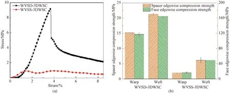
Fig.12 Compression stress and strength: (a)flatwise compression stress-strain curves of WVSD-3DWSC and WVSS-3DWSC; (b)edgewise compression strength of WVSS-3DWSC and WVDS-3DWSC
2.4 Compression strength of WVSS-3DWSCs with different V-shaped angles
Four different V-shaped angles were designed, namely 42°, 28°, 22°, and 15°. It can be seen from Fig.13(a) that the change of the V-shaped angle has no effect on the flatwise compression failure mode of the V-shaped pile yarn. In Fig.13(b), two stress peaks appear in the flatwise compression stress-strain curve when the V-shaped angle is 42° and 28°. It indicates that when the V-shaped angle is 15°and 22°,the V-shaped structure fails to form a triangular stressed structure, and the pile yarn collapses on the same side as the I-shaped pile yarn. In addition, it can be found that as the V-shaped angle decreases, the flatwise compression stress also decreases. Since the yarn parameters of the WVSS-VA42 are different from those of the other three samples, only the stress-strain curve of the WVSS-VA42 is discussed. As the V-shaped angle decreases, the triangle’s top angle also decreases, which changes the position of the triangular structure’s gravity center. The gravity center is the center of a triangle structure, which would carry and distribute forces from the outside structure. When the triangle’s top angle decreases, the gravity center moves closer to the triangle’s apex, perhaps resulting in a more unstable construction.
As can be seen from Fig.13(c), both the flatwise compression strength and modulus decrease with the reduction of the V-shaped angle. The decline of the flatwise compression strength is greater, which is also owing to the failure to establish a triangular stressed structure due to the narrow clamping angle.
3 Conclusions
Two kinds of 3DWSFs with different binding methods were firstly designed: weft V-shaped and weft I-shaped fabrics. The composites with two types of pile yarn densities and four kinds of V-shaped angles were prepared for the V-shaped composites in the weft direction. Through the compression test of the above samples, the conclusions are as follows.
1)The WVSS-3DWSF compressed better than the WISS-3DWSF. When subjected to the external stress, the weft V-shaped fabric recovered to 95.7%, while the height of the weft I-shaped fabric recovered to only 88.3%. The average elastic recovery rate of WVSS-3DWSF was 59.39%, which was 1.5 times that of the WISS-3DWSF. The fixture mechanism of the V-shaped pile yarn, the triangular stressed structure generated by the pile yarns and top and lower panels when stressed, and the yarn resistance all contributed to this.
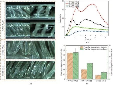
Fig.13 Compression properties of composites: (a) SEM images of WVSS-VA28, WVSS-VA22, and WVSS-VA15; (b) flatwise compression stress-strain curves of WVSS-VA42, WVSS-VA28, WVSS-VA22, and WVSS-VA15; (c) histogram of flatwise compression strength and modulus of WVSS-VA28, WVSS-VA22, and WVSS-VA15
2)When the interlayer pile yarn density was the same, the WVSS-3DWSC and the WISS-3DWSC had identical flatwise compression and edgewise compression performance. When subjected to flatwise compression, the main part of the V-shaped pile yarns turned white due to stresses, except for the stress cracking at the connection between the V-shaped pile yarn and the panel layer. The WVSS-3DWSC offered higher edgewise compression stability than the WISS-3DWSC, and when the lateral compression was on, the panels were not considerably damaged, with the damage predominantly taking the form of panel buckling and V-shaped pile yarn collapsed failure.
3)Increasing the density of V-shaped pile yarns improved the compression performance of the WVSD-3DWSCs in flatwise and edgewise compression. However, the damage mode was comparable to that of WISS-3DWSCs because the resin wrapped the pile yarn into a thick V-shaped column, which lost toughness and did not form a triangular stressed structure.
4)When the V-shaped angle was 28° and 42°, the flatwise compression stress-strain curve showed two stress peaks, showing good anti-compression cushioning effectiveness. The V-shaped structure could not form a triangular stressed structure when the V-shaped angle was 15° or 22° and the pile yarn collapsed on the same side as the I-shaped pile yarn. The flatwise compression stress decreased as the V-shaped angle decreased.
猜你喜欢
杂志排行
Journal of Donghua University(English Edition)的其它文章
- Oscillation Reduction of Breast for Cup-Pad Choice
- Optimization for Microbial Degumming of Ramie with Bacillus subtilis DZ5 in Submerged Fermentation by Orthogonal Array Design and Response Surface Methodology
- pth-Moment Stabilization of Hybrid Stochastic Differential Equations by Discrete-Time Feedback Control
- Semantic Path Attention Network Based on Heterogeneous Graphs for Natural Language to SQL Task
- Device Anomaly Detection Algorithm Based on Enhanced Long Short-Term Memory Network
- Image Retrieval Based on Vision Transformer and Masked Learning