Modified Sliding Mode Observer-based Direct Torque Control of Six-phase Asymmetric Induction Motor Drive
2023-10-28,
,
(Department of Electrical Engineering,Sardar Vallabhbhai National Institute of Technology,Surat 395007,India)
Abstract: In this study,a six-phase induction asymmetric induction motor (SPAIM) was examined,whose performance surpasses that of its three-phase counterpart,with regard to the torque density,torque pulsation,fault tolerance,power rating per inverter lag,and noise characteristics.Speed-encoder-less direct torque control (DTC) for SPAIM with virtual voltage vectors (VVVs) and a modified sliding mode observer (MSMO) are described.The SPAIM model was developed using a stationary α-β frame for DTC.The conventional DTC of the SPAIM drive is a simple extension of DTC for a 3-Φ motor drive that yields higher distortion in the stator currents.To mitigate the large amount of distortion in the stator current,VVVs were used to significantly reduce the harmonic content in the stator currents.Furthermore,to overcome the large amount of chattering observed in the case of a traditional sliding mode observer,particularly under low-speed operation,the MSMO was employed to reduce chattering even under low-speed operation.The performance of the proposed observer was verified under all the operating conditions suitable for the propulsion mode of an electric vehicle using Matlab/Simulink,and the results were experimentally validated.
Keywords: Direct torque control,multiphase induction motor drive,sliding mode observer,space vector modulation
1 Introduction
Multiphase induction machines have widespread applications in electric traction,electric ship propulsion,electric aircraft,and electric vehicles owing to several attractive features,such as their high torque densities,small torque ripples,good under fault conditions,and low maintenance costs[1-4].Owing to these features,they have attracted considerable research attention in recent years.Multiphase machine,including six-phase machines,can be broadly classified into two categories: asymmetric and symmetric.The six-phase induction asymmetric induction motor (SPAIM) consists of two sets of three-phase stator windings electrically displaced by 30°[1].Most of the aforementioned applications require variable-speed operation for precise control.Therefore,the closed-loop control of these drives is implemented using feedback sensors,such as voltage,current,and speed sensors.The numerous sensor requirements for the control of multiphase machines significantly increase the cost and complexity of the system.
To achieve more precise speed control of electric drives,additional sensors,such as speed sensors,are required for the implementation of various control algorithms.However,in certain applications,motor drives can be subjected to hostile operating conditions,which may cause maloperation or failure of such sensors,leading to the failure of the control algorithm.Therefore,the control of electric drive systems without the use of speed sensors is an attractive method[5-8].Speed sensors increase the cost and complexity of the drive system and reduce its reliability.Speed-sensor-less operation of drives has several advantages,e.g.,simpler implementation of control strategies,lower costs for the implementation and maintenance of drive systems,and enhanced robustness and reliability[9-10].
Speed estimation methods for sensor-less speed control of electric drives can be broadly divided into two groups.Methods in the first group are based on signal injection and can be further classified into two categories: injection of a high-frequency signal and injection of a low-frequency signal.Signal-injection methods depend on the slot harmonics of the rotor and contrived saliency.They can estimate very low (even zero) speeds.However,it is difficult to extract the correct information for signal injection,because the contrived saliency is assumed to vary among machines.Therefore,the use of these methods is limited even though they provide accurate estimates of the speed,particularly at low speeds and zero speed[5].The second group of methods is based on the mathematical modeling of an induction motor (IM),e.g.,Kalman filter observers[10-13],reduced-order observers,model reference adaptive systems[14-18],adaptive state observers,and sliding mode observers(SMOs)[19-26].The sensor-less DTC of an IM drive using an extended Kalman filter,which provides accurate estimates of both speed and torque even at low speeds and zero speed,along with a constant switching frequency,was discussed in Ref.[11].The sensor-less loss model control of a multiphase IM was explained in Ref.[12].A comparative study of an extended and unscented Kalman filters for the encoder-less control of an IM drive was performed in Ref.[13].In Ref.[14],the speed estimation of an IM drive using an equivalent circuit impedance-based model reference adaptive system (MRAS) did not require the rotor flux to be determined.Speed estimation based on active and reactive power-based MRAS was discussed in Ref.[15].In Ref.[16],a modified MRAS based on the error in the stator current was developed.Sensor-less backstepping control based on a robust simplified dynamic observer was proposed in Ref.[17].A super-twisting SMO-based MRAS for the speed-encoder-less DTC of a multiphase induction motor (MIM) drive was discussed in Ref.[18].
Modeling errors affect the performance of almost all estimators,with the exception of the SMO.The SMO exhibits better operating characteristics than other estimators under modeling uncertainties because it has an inherent variable structure.Good control performance is not ensured even when an accurate machine model is available at the start of the operation,owing to the uncertainties of the system,for example,external disturbance and internal variation of parameters,which are mostly due to temperature increases.Because the SMO has a variable structure design,it has superior robustness against parameter variation to the other estimators discussed above.It is a promising solution for the sensor-less control of IM drives owing to its robustness to parameter variations,ease of implementation,and rejection of disturbances[19].Recently,extensive research has been conducted on the use of the SMO for the sensor-less control of industrial drives.The principles of SMO design and its applications in electric drives were discussed in Ref.[20].The sensor-less rotor field-oriented control of an IM using SMO was described in Ref.[22],and various reaching laws were adopted to improve the performance of the observer with regard to chattering.Encoder-less block control with DTC of the SPAIM drive was described in Ref.[23].The sensor-less control of a five-phase IM drive using a variable structure observer,in which the inputs to the observer are thed-andq-subspace voltages and currents and the estimated speed,was discussed in Ref.[24].The sliding mode current-control-based rotor flux-oriented control of a solar PV-fed IM drive with an integral SMO was discussed in Ref.[25].In Ref.[26],a discrete SMO-based MRAS for online speed estimation of a 3-ϕIM was discussed in detail.Encoder-less vector control with open-phase fault diagnosis was described in Ref.[27].The sensor-less control of a 3-ϕIM with a reconstruction algorithm for the current to provide immunity against current sensor failure was discussed in Ref.[28].The adaptive active disturbance rejection-based Encoder-less control of a 3-ϕIM was introduced in Ref.[29].A detailed discussion and review of PLL-and FLL-based online speed estimation techniques were presented in Ref.[30].Online speed and parameter determination to provide robustness against parameter variations was described in Ref.[31].
In this study,the speed-sensor-less modified DTC of the SPAIM drive was performed using virtual voltage vectors (VVVs).The use of the conventional DTC method increases the harmonic content in the stator current.However,with the application of a virtual space vector,the current harmonics are reduced to a greater extent compared with the conventional DTC technique for SPAIM.A modified sliding mode observer (MSMO) is utilized to determine the flux and speed of the rotor.The traditional SMO uses a signum function that increases the chattering.To solve this problem,a tangent-sigmoid (tansig) function is used instead of a signum function.Another problem associated with the conventional SMO is that the estimation errors and amount of chattering increase at low speeds.Because the performance of the observer is affected by how the state variables reach the sliding surface,it can be optimized using a constant rate reaching low under both steady-state and transient operating conditions.
This manuscript is organized as follows.Section 1 presented a brief literature review,along with the motivations and objectives of the study.Section 2 describes the modeling of the SPAIM.The DTC of the SPAIM using VVVs is discussed in Section 3.Section 4 details the design and development of the SMO for the SPAIM drive.Section 4 discusses the stability analysis of the SMO,and Section 5 presents detailed simulation analyses of the proposed system,along with simulation and experimental results and discussions.Finally,the conclusions are presented in the Section 6.
2 Mathematical modeling and system configuration
Fig.1 shows a block diagram of the SPAIM drive system,which primarily consists of an SPAIM,a six-leg voltage source inverter (VSI),an AC-DC converter,and a control module.
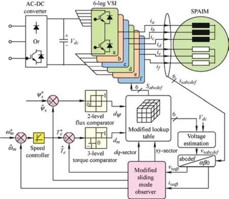
Fig.1 Block diagram of the SPAIM drive with the MSMO
The SPAIM comprises two sets of 3-Φstar-connected stator windings spaced electrically at 30°.The six-leg VSI comprises two insulated-gate bipolar transistors in each leg,and the midpoint of each leg is connected to each phase,as shown in Fig.1.The DC link voltage (Vdc) for the six-leg VSI is constant and ripple-free and is obtained from the AC-DC converter.The modified DTC scheme is used for closed-loop control of the SPAIM drive,in which the MSMO estimates the speed,stator flux,and torque.The switching table generates gate pulses for the six-phase VSI based on the torque and flux statuses received from the torque and flux comparators,respectively.
Detailed mathematical modeling of the six-phase IM was performed using the vector space decomposition approach presented in Ref.[6].For reducing the required number of voltage sensors,the 64 possible switching combinations,along with the knowledge of the DC link voltage,were employed to determine the six-phase voltages using Eq.(1).
Here,υ=π/6.The transformation matrix (Ts) is used to convert six-phase AC quantities into three two-phase mutually orthogonal systems (α-β,x-y,and 0102) and is given by Eq.(2).It maps the fundamental component and harmonic component of order 12n±1 in theα-βsubspace,the harmonic component of order 6n±1 in thex-ysubspace,and the harmonic component of order 3nin the 01-02 subspace.The electromagnetic torque is produced only by the current components of theα-βsubspace.
Dynamic modeling of the SPAIM was performed in a stationary reference frame.The transformation matrix was used to develop the equations for the voltages and fluxes of the stator and rotor in the stationary reference frame.
3 Modified DTC of SPAIM drive
In the conventional DTC scheme for the SPAIM,the large switching vectors of theα-βsubspace are considered.However,their effect on thex-ysubspace is not considered in the conventional DTC.Therefore,in a conventional DTC-fed SPAIM,a large harmonic content in the stator current is produced,which adversely affects the performance of the drive.The problem of large harmonics in the stator current can be mitigated using a modified DTC scheme,as discussed in Refs.[32-33].This requires two switching tables,as shown below.Tab.1 is identical to the switching table of conventional DTC,and Tab.2 consists of the medium switching vectors from theα-βsubspace.Detailed discussions on the reduction of stator-current harmonics are presented in the following subsection.
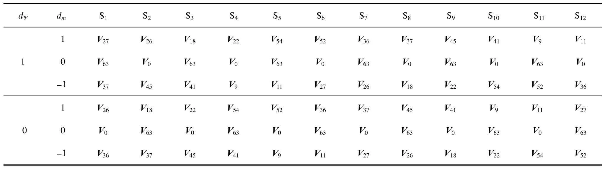
Tab.1 Switching table 1
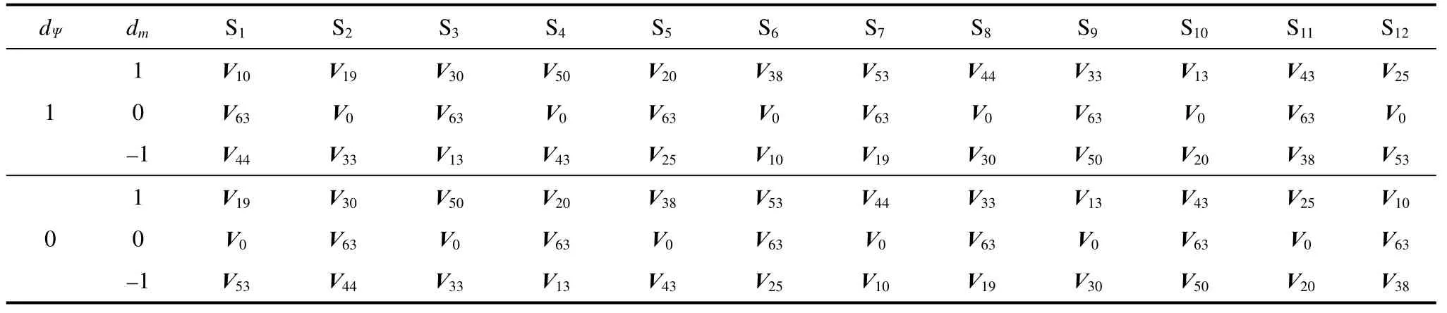
Tab.2 Switching table 2
Suppose that the torque and flux both need to be increased and that the flux vector is in Sector 1 (S1).Then,the voltage vectorsV27andV10are selected from Tabs.1 and 2,respectively.These voltage vectors have the same direction in theα-βsubspace.Hence,they have the same impact on the torque and flux behaviors.However,they have opposite directions in thex-ysubspace.Analogous to theα-βsubspace,thex-ysubspace is also divided into 12 sectors.It is divided into two half-circles (HC1 and HC2),as depicted in Fig.2b.The bottom two equations in Eq.(3) are utilized to determine the location of the flux in thex-ysubspace.If the flux vector lies in HC1,vectorV10is selected; if it lies in HC2,V27is selected (Fig.2).Hence,by selecting vectors from opposite half-circles,the resultant flux in thex-ysubspace can be minimized.Therefore,the distortion of the current waveform is significantly reduced.
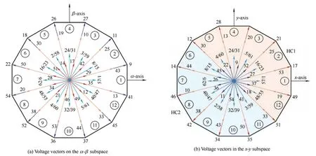
Fig.2 Voltage-vector orientation
4 Design of sliding mode observer for SPAIM drive
In this section,design equations for the SMO for online speed estimation are presented.
4.1 Conventional sliding mode observer
The dynamic model of the SPAIM in the stationaryα-βcoordinate system with stator current and rotor flux linkages is expressed as
Eq.(8) can be rewritten as
wherem1,m2,m3,andnare defined as follows
Common terms in Eqs.(9) and (10) include the stator current and rotor flux.Therefore,these terms can be referred as coupling terms between theαandβaxes.This implies that the common coupling term can be replaced with the sliding mode functionfαβgiven by Eq.(11).Hence,the sliding mode function for convergence can provide the estimated values of the stator currentand rotor flux linkages[20].
From the dynamic model of the SPAIM in the stationaryα-βcoordinate system,the equation for the design of the SMO for current can be given as
The equation of the SMO for flux can be given as
Here,fαandfβare sliding mode functions defined as follows
whereK0> 0.K0represents the gain of the sliding mode function.Higher values correspond to better dynamic performance but also larger amounts of chattering.SαandSβare defined as follows
For the conventional SMO,the sliding mode surface(SMS) can be defined as follows
4.2 Modified SMO with constant rate reaching law for sensor-less SPAIM drive
The conventional design of the SMO focuses on the system stability rather than the method of reaching the sliding surfaces.This can significantly affect the performance of the SMO.Specifically,it can reduce the amount of chattering and result in fast-reaching transient performance.Therefore,a constant rate reaching law (CRRL) is used for the design of the flux observer.
In this case,the SMS can be defined as follows
wherek1> 0 andk2> 0.
In defining the SMS,both the error in the estimation and rate of error in the estimation of the stator current are considered.The proportion of error in the estimation and the rate of error in the estimation can be regulated by adjusting the parametersk1andk2.
The current observer can be defined as follows
wherefα′ andfβ′ are sliding mode functions defined as
To derive the equation of the rotor flux observer,the derivative ofSIcan be obtained using Eqs.(9)-(13)and (18)
The dynamic performance of the SMO is improved by using the constant-rate reaching law for the design of the flux observer.Here,the following CRRL is adopted[19-21]
whereg> 0.The SMO for the rotor flux linkages with the CRRL can be expressed by Eqs.(20) and (21)
The estimated speed of the rotor can be obtained from the estimated rotor flux linkages as follows
If multiply the first and second rows byand,respectively,Eq.(23) can be written as
From Eq.(22),the real-time velocity can be determined as follows
The most important advantage of this SMO is that the estimation error of the real-time velocity is not fed back to the observers for the stator flux and current.Fig.3 shows the structure of the MSMO.
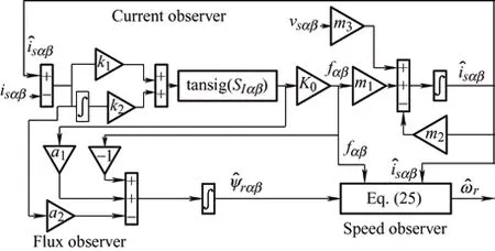
Fig.3 Structure of the MSMO
4.3 Stability analysis of CRRL-based SMO
The Lyapunov function for the proposed observer can be expressed as
From Eq.(26),it is clear that Lyapunov functionVis positive-definite,andV˙ can be expressed as
From Eq.(21),if [SIα(tansig(SIα))+SIβ(tansig(SIβ)) >0 andg> 0,the derivative of the Lyapunov function is negative and definite.Hence,according to Lyapunov’s theory of stability,the observer is asymptotically stable.
5 Results and discussion
The modified SMO-based sensor-less DTC technique discussed in the previous section was tested on a laboratory-scale prototype of the SPAIM drive.The SPAIM parameters are presented in Tab.3.The entire control algorithm and the modified SMO switching table were incorporated into the TMS320F28379D controller board.The proposed algorithm was implemented at a sampling rate of 100 µs.A CT-based current sensor was used to measure the phase current.An isolation circuit was used to amplify the pulses for pulse width modulation generated by the controller before they were fed to the 6-VSC.An optical encoder operating at 1 024 pulse per revolution was used to measure the rotor speed.The measured speed was only used for comparison with the observed speed.
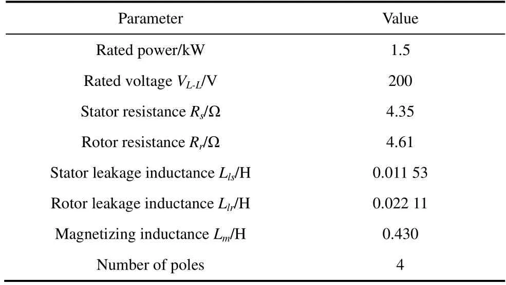
Tab.3 Motor parameters
The torque and flux hysteresis bands were 0.2 N·m and 0.02 Wb,respectively.The proposed algorithm was tested under steady-state and dynamic conditions.The laboratory test setup is shown in Fig.4,and a detailed discussion of the results is presented in the following subsections.
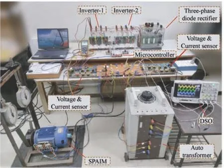
Fig.4 Photograph of the laboratory test setup
5.1 Simulation results
The performance of the proposed MSMO was evaluated through a simulation using Matlab/Simulink,and the results were validated through experimentation over a wide range of speeds.The SPAIM parameters used in the simulations and experiments are presented in Tab.3.The sampling rate was set to 10 kHz for the simulations.The stator flux reference was 0.51 Wb.The flux and torque hysteresis bands were set to 0.02 Wb and 0.2 N·m,respectively.
Simulations were conducted under different operating conditions.Fig.5 presents various electrical performance parameters,such as the phase voltage(va1,va2),phase current (ia1,ia2),andα-βsubspace current for a reference speed of 1 400 r/min and dynamic load variations.
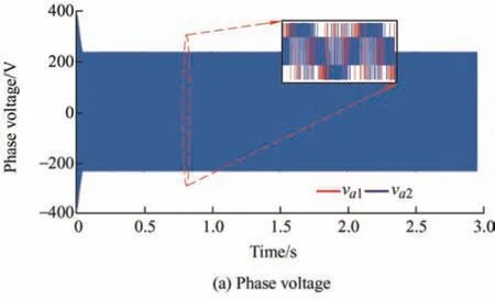
Fig.5 Simulation results for a speed reference of 1 400 r/min and dynamic load variations
Fig.6 shows the performance of the proposed MSMO under a constant load of 6 N·m and dynamic speed variations.The SPAIM started with a speed command of 1 000 r/min,and att=1.5 s,the speed was increased stepwise from 1 000 r/min to 1 400 r/min.As shown in Fig.6a,the actual and estimated speeds were almost identical.Furthermore,as shown in Fig.6b,the estimation error was used to closely monitor the deviations from the actual and estimated speeds,which were small.Fig.6c presents the stator currentsia1andia2.

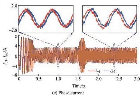
Fig.6 Simulation results for a constant load and the speed increasing from 1 000 r/min to 1 400 r/min
Fig.7 presents the responses of the MSMO at a constant speed of 1 400 r/min and different load torques.During the time interval of 0.5-1 s,the SPAIM operated with no load.Att=1 s,the load changed to 3 N·m,and att=2 s,it changed to 6 N·m,as shown in Fig.7c.As shown in Figs.7a and 7b,the MSMO exhibited good speed tracking performance.The speed estimation error was small,i.e.,approximately 5 r/min,as shown in Fig.7b.

Fig.7 Simulation results for a constant speed of 1 400 r/min and dynamic load variations
To evaluate the performance of the MSMO under speed reversal,the speed reference was varied from+50 r/min to –50 r/min.The performance of the observer is presented in Fig.8.As shown,the observer accurately tracked low and negative speeds.
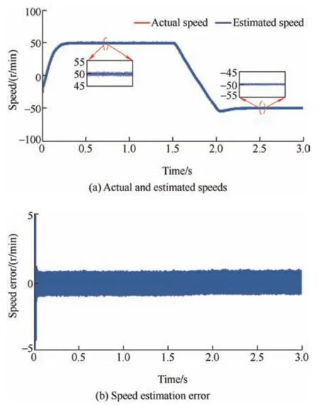
Fig.8 Simulation results for speed command variation from+50 r/min to –50 r/min
5.2 Experimental results
To validate the simulation results,a prototype model for Encoder-less DTC of the SPAIM drive was developed,and a modified SMO-based DTC control scheme was implemented using a TMS320F28379D controller board with a sampling frequency of 10 kHz.The proposed algorithm was tested under steady-state and dynamic conditions.Only the measured speed obtained using the encoder was used for comparison with the observed speed.
Fig.9 represents the waveforms of the phase voltages(va1,va2),stator phase currents (ia1,ia2),and stator currents (iα,iβ) on theα-βsubspace with a constant speed command of 1 400 r/min and dynamic load variations.The motor was started under a light load condition (0.6 N·m),after which the load was increased to 4 N·m and then to 6 N·m.These waveforms are magnified in Figs.10 and 11 for different load conditions.Fig.10 shows the test results for the estimated speed,estimation error of the speed,and phase currents (ia1,ia2) for dynamic speed variations.The motor was started with a speed command of 1 000 r/min,after which a stepwise increase in the speed command from 1 000 r/min to 1 200 r/min was applied with a constant load of 4 N·m.The results indicated that the speed transition was tracked smoothly by the observer.Magnified views of the initial transients for the 1 000 r/min and 1 200 r/min speed commands are presented.Fig.11 shows the experimental results obtained with a constant speed command of 1 000 r/min and dynamic load variations.Magnified views of the initial transients under the medium-load condition and with a 6 N·m load are presented.
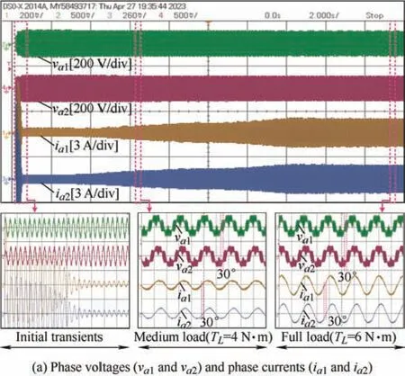
Fig.9 Experimental results for a speed command of 1 400 r/min and dynamic load variations
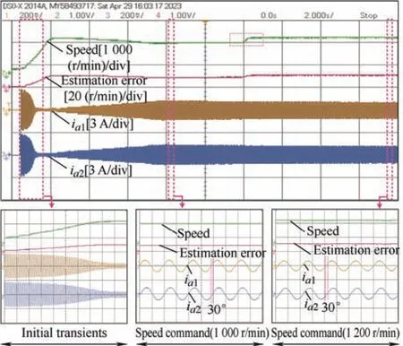
Fig.10 Experimental results for the estimated speed,estimation error of the speed,and phase currents (ia1,ia2) with dynamic variations in the speed command
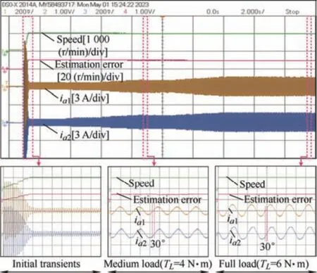
Fig.11 Experimental results for the estimated speed,estimation error of the speed,and phase currents (ia1,ia2) with a speed command of 1 000 r/min and dynamic load variations
5.3 Comparative performance analysis
The effectiveness of the proposed modified SMO-based DTC method for the SPAIM drive was verified by comparing it with previously reported rotor speed estimation techniques with regard to the speed estimation error and torque ripples under different operating conditions.Tab.4 presents a comparative performance analysis of the different speed estimation techniques.
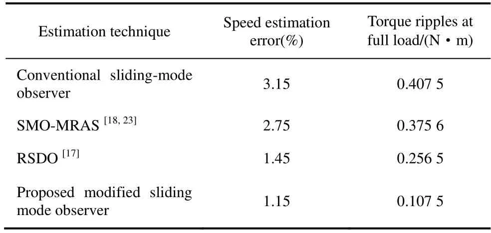
Tab.4 Comparative performance analysis
As shown,the proposed modified SMO-based DTC method for the SPAIM drive had the smallest speed estimation error and torque ripple under different operating conditions.
6 Conclusions
This paper proposes speed-encoder-less modified DTC of the SPAIM drive with an MSMO.The utilization of virtual switching vectors significantly reduces the stator current distortion compared with conventional DTC.
(1) The primary contribution of this study is the design of the MSMO using the reaching law and tansig function for Encoder-less operation of the SPAIM drive.The problem of large amounts of chattering at the sliding surface,particularly at low speeds,was solved by applying the MSMO.
(2) The major advantage of the MSMO is that it can accurately estimate extremely low speeds and even zero speed.By applying the proposed observer,the estimation error was reduced by 1.15%.
(3) Encoder-less operation reduces the cost and complexity of the drive system and improves its reliability.
(4) The performance of the SPAIM drive system with the proposed observer was tested under various operating conditions.The results indicated that the performance of the SPAIM drive with the MSMO is satisfactory,and it is suitable for various applications in electric traction,electric ship propulsion,electric aircraft,and electric vehicles.
杂志排行
Chinese Journal of Electrical Engineering的其它文章
- A Multi-scale Smart Fault Diagnosis Model Based on Waveform Length and Autoregressive Analysis for PV System Maintenance Strategies*
- TSKARNA-norm Adaption Based NLMS with Optimized Fractional Order PID Controller Gains for Voltage Power Quality
- Quantitative Comparison of Modular Linear Permanent Magnet Vernier Machines with and without Partitioned Primary*
- A Review of Variable-inductor-based Power Converters for Eco-friendly Applications:Fundamentals,Configurations,and Applications*
- Fast Solution Method for the Large-scale Unit Commitment Problem with Long-term Storage*
- Value Evaluation Method for Pumped Storage in the New Power System*