A Review of Variable-inductor-based Power Converters for Eco-friendly Applications:Fundamentals,Configurations,and Applications*
2023-10-28,*,.
, *, .
(1.School of Automation,Guangdong University of Technology,Guangzhou 510000,China;2.School of Engineering,Deakin University,Melbourne 3000,Australia)
Abstract: Modern eco-friendly industries such as renewable energy systems,electric vehicles (EVs),and light-emitting diodes(LEDs) have led to technological advancements in power electronics.Switching-based power converters have limited working ranges and can cause significant harmonics and oscillations in the output voltage and current.Introducing variable inductors can help solve this problem by changing the inductance without resorting to extreme switch duty cycles.Despite their advantages,there is still a lack of comprehensive reviews of variable inductor applications in power converter design.A thorough and in-depth review of variable inductance control in power conversion is presented,including its significance,working principle,core structure,modeling method,and typical applications.Traditionally,an inductor works in its linear magnetic region; its inductance in a power converter is considered constant,and the converter operates under fixed working conditions.However,a broad range of working conditions is required for power converters in practical applications.This is typically realized by changing the duty cycles of the switches.The working principle of variable inductance is reviewed,and the application of variable inductance control in power converters is presented,which will further help power electronics researchers and engineers design flexible and resilient power converters.
Keywords: Variable inductors,magnetic saturation,magnetically controlled inductors,power converter
1 Introduction1
In 1751,Franklin discovered that electrical charges emanating from a Leyden bottle can induce magnetism in a steel needle[1].Oersted discovered the electromagnetic effect in 1820.He placed a needle underneath a wire and was surprised to observe it rotating perpendicularly when he turned on the power.Upon reversing the current,he noticed that the needle changed its rotational direction[2].This led to the discovery of a prologue of electromagnetism and inaugurated the period of electromagnetism.Faraday’s major breakthrough came in 1831 when he discovered that an electric current was generated in a conductor when a part of it in a closed circuit was cut through magnetic inductance while moving through a magnetic field[3].The inseparable link between electricity and magnetism paved the way for a sequence of major breakthroughs in the principles of electricity and magnetism by Volta,Coulomb,Gauss,and Henry,among all others[4],who collaborated to deepen and broaden the concept of electromagnetism.
An inductor suppresses abrupt variations in the current,ensuring a smooth,gradual change in the current flowing through it,and stores the magnetic energy[5].The earliest form of an inductor was discovered by Faraday,who used an iron-core coil to observe electromagnetic induction[6].Owing to its important role in power electronics,the wide application of inductors has significantly promoted the development of electrical engineering.
In recent years,there has been a surge in global pollution and a strong push for renewable energy sources,such as solar and wind power generation systems and electric vehicles[7].Unfortunately,rapid progress has also posed formidable obstacles owing to the lack of technological advancements in power electronics.
Owing to the continuous developments in the field of power electronics,power converters are expected to achieve a wider working range and higher transmission efficiency.The commonly employed control scheme for general-purpose switching power converters is pulse-width modulation (PWM)-enabled control,which operates by dynamically adjusting the duty cycle of the switches to achieve voltage and power modulation[8].However,an excessively small duty cycle leads to discontinuity in the inductor current.Zero-voltage switching (ZVS) may become invalid[9],causing the converter to overstrain the switch with an excessive voltage and undermining the reliability of the circuit[10].
Pulse frequency modulation (PFM) and phase-shift modulation (PSM) are commonly employed principal control approaches in resonant power converters[11].Although these methods yield satisfactory results,designing magnetic devices that operate in a broader frequency range has become increasingly arduous[11].To address this issue,alternative methods based on PFM and PSM have emerged with the aim of narrowing frequency fluctuations[12-15].
Some researchers have investigated controlling converters by modifying previously fixed parameters.The first strategy was to introduce a variable-capacitance approach.There are two primary methods to implement a variable-capacitance approach.
(1) Manipulate the intermediate energy storage medium or adjust the distance between the positive and negative terminals within a capacitor[16-17].
(2) By altering the circuit structure,the two edges of the variable capacitors can equivalently represent a new capacitance value[18-19].
Introducing a variable capacitance allows the output voltage of the resonant converter to resonate at the resonant frequency,which helps improve the efficiency and reduces the size of the converter.However,it is challenging to linearly change the capacitance and reduce the size of variable capacitors.
In 1916,Alexanderson and Nixdorff[14]developed a variable inductor to resolve the issues associated with variable capacitors.Over the past century,as inductors have been increasingly used,the possible applications of variable inductors have dramatically increased.Early applications focused on signal transmission in wireless telephones[14]equipped with military ships and planes during World War II[15,20].In recent decades,variable inductors have been applied in numerous ways,including low-power switching power supplies[21],resonant converters[10,22-25],power factor correction (PFC)[21,26-27],and fluorescent lamp driver applications[28-38].Variable inductors have become a remarkably mature magnetic control technology that is widely used in solar energy[39-41],electric vehicles[42-44],light-emitting diode (LED) drivers[28,33,45],and other fields.Nevertheless,realizing extensive practical applications of variable inductors relies upon both selecting the appropriate variable inductance for use in different converters and devising variable inductors that meet crucial design requirements.This has been a significant challenge for researchers and engineers.
This review aims to present and investigate the operational mechanism of variable inductors through an inductance lens by surveying the up-to-date research on variable inductors,encompassing core configuration,simulation,and utilization.Engineers and designers can understand the fundamentals of variable inductors and employ relevant components in their designs.
The remainder of this paper is organized as follows and is shown in Fig.1.Past of variable inductors:Section 1 expounds on the development of variable inductors.Presence of variable inductors: A profound analysis of the working principles of variable inductors is presented in Section 2,and cutting-edge research on variable inductors is analyzed in detail in Section 3.In Section 4,a modeling method for variable inductors is proposed and presented.Section 5 discusses the applications of variable inductors in power converters.Future of variable inductors: In Section 6,the difficulties of variable inductors are summarized,and possible future research directions for variable inductance are envisioned.Finally,Section 7 presents the conclusions and provides a summary.
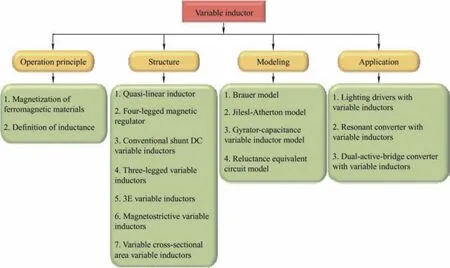
Fig.1 Article outline map
2 Operation principle of variable inductors
A variable inductor,as shown in Fig.2,is composed of a coil and a magnetic core.The reluctance of the magnetic core is altered by changing the current in the control winding to change the equivalent inductance at both ends of the winding.The study of electromagnetism involves investigating the characteristics of electricity and magnetism and their interactions,working principles,and practical applications.At the microscopic level,substances acquire their magnetic properties from the respective currents generated by the aligned movement of electrons[46].Permanent magnets,such as those used in generators and electrical systems,obtain magnetic fields from the current generated by the movement of molecules.Moreover,the direction of the magnetic domains in the material corresponds to the motion of the electrons within the material,forming a magnetic lattice.
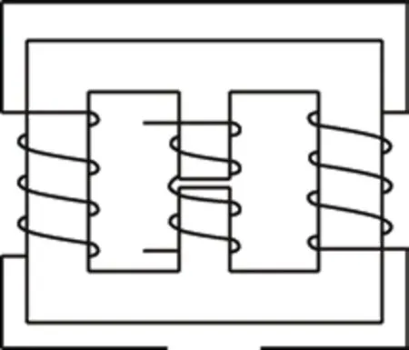
Fig.2 Structure diagram of a variable inductor
2.1 Magnetization of ferromagnetic materials
Ferromagnetic substances can develop magnetic properties because they possess small regions of spontaneous magnetization called domains.This distinguishes them from non-magnetic materials.For the macroscopic effect,generating an external magnetic field via an electric current is necessary to induce magnetization in magnetic materials.Owing to the effect of an external field,the magnetic domains within the material rotate toward the direction of the applied field,thereby augmenting the internal magnetic field of the material.With the gradual amplification of the external magnetic field,an increasing number of domains tend to shift in the direction of the given external field,consequently elevating the magnetic induction parallel to the outer field.
The magnetic flux density (B) is a physical quantity that characterizes the potency and orientation of a magnetic field.The magnetic induction magnitude is directly proportional to the magnetic induction intensity,whereas the opposite is true for a weaker magnetic induction.The magnetic field intensity (H) is used to compute the magnetic induction intensity.
whereμ0is the permeability of the vacuum space,which is equal to 4π×10-7H/m,andrμis the relative permeability of magnetic materials,which changes in different magnetic materials.While magnetizing ferromagnetic materials,the relative permeability will display a nonlinear change.
A nonlinear relation exists betweenBandHCurveCin Fig.3 illustrates that asHrises,Bexperiences a steady increase initially (segmentO-a).Subsequently,Bundergoes an accelerated increase that almost has a linear pattern (zonea-b) asHcontinues to increase.The rate of change of the increase inBslows down again asBfurther increases.When pointcis reached,no matter how muchHincreases,Bhardly increases,i.e.,saturation occurs.After the magnetization curve reaches pointb,the magnetic field intensity continues to increase,and the growth rate of magnetic induction intensity gradually slows down.Therefore,the region surrounding this curve is called the inflection point of the curve.
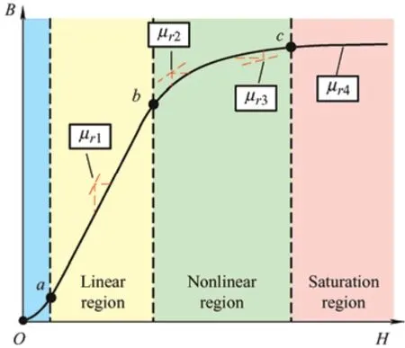
Fig.3 Magnetization curve
It can be seen from Eq.(1) that the permeabilityμis equal to the ratio of the magnetic induction intensityBto the magnetic field intensityHin ferromagnetic materials.Therefore,the permeability can be expressed as the slope of the curve in Fig.3.As shown in Fig.3,when the curve is in the linear region,the slope remains constant; therefore,the magnetic flux remains constant.In the nonlinear region of the curve,the slope of the curve changes; therefore,the magnetic flux also changes.
Eq.(3) shows the expression forBand is related toM,which is defined as the magnetic dipole moment per unit volume (density of permanent or induced magnetic dipole moments in a magnetic material).
The change in magnetization is caused by the magnetic domain within the ferromagnetic material being altered by an external magnetic field,that is,the magnetic field produced when a ferromagnetic material is magnetized by a magnetic field.When the saturation region is reached,all the magnetic domains are oriented in the same direction.Therefore,Mis at its maximum.At this point,the slight increase in the magnetic induction is only due to an increase in0μandH.
If the ferromagnetic material is magnetized along the magnetization curve from the fully demagnetized state to saturation,whereB=Bsatas displayed in Fig.4,and if the external magnetic fieldHis reduced,Bwill no longer decrease according to the original initial magnetization curve as illustrated by the dashed line in Fig.4,but will decrease more slowly along the higherB.This is because the domains rotated by the external magnetic field maintain the direction of the external magnetic field.Even when the external magnetic fieldH=0,B≠0,i.e.,there is still residual magnetic flux densityBr.This non-coincidence of the magnetization and demagnetization curves represents the irreversibility of magnetization.The change ofBlags behind that ofH,which is called the hysteresis phenomenon.If this residual magnetic induction is to be eliminated,an opposite external magnetic field needs to be applied,and the strength of this reverse magnetic fieldHcis called the coercive force.When the reverse magnetic field continues to increase,an opposite magnetic field will be generated on the ferromagnetic material.At this point,a closed-loop loop can be obtained,which is called a hysteresis loop.
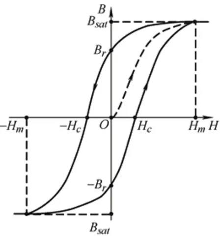
Fig.4 Hysteresis effect
Similar to the magnetization curve,the shape of the hysteresis loop is material-dependent and depend onBsat,Br,Hc,and other important parameters determined by different materials.Soft magnetic materials are easily modifiable in their magnetic domain; thus,they have a lower coercive force and a narrower hysteresis loop.Conversely,hard magnetic materials have domains that are difficult to alter,providing them with a higher coercive force and a higher residual magnetic flux than soft magnetic materials.These features provide favorable conditions for the selection of magnetic core materials for variable inductors.
2.2 Definition of inductance
According to the relationship between electricity and magnetism described earlier,when the currentiflows through the coil,a magnetic flux or magnetic chain is generated,assuming that the magnetic permeabilityμof the magnetic medium in the coil is constant,andψ(t) is proportional toi.
According to the electromagnetic mechanism,the time-varying fluxϕ(t) passing through a closed-loop wire generates an induced voltage in the wire.The relationship between the induced voltagevi(t) and magnetic fluxϕ(t) can be determined according to Faraday’s law.Meanwhile,if the winding has multiple turns,the relationship between the total fluxψ(t)and the magnetic flux can be obtained.
whereNis the number of turns of the coil,andLis the self-inductance coefficient of the coil,often abbreviated as self-inductance or inductance.This is the most important definition of an inductor.
The scalar value of the magnetic fluxφpassing through the surface of the magnetic core is related to the magnetic flux densityB,as follows
whereBis the surface density of the magnetic flux and dSis the vector perpendicular to the surface dSin that direction with a magnitude equal to dS.If the distribution of the flux density is uniform and perpendicular to the entire surface areaA,then Eq.(7)can be derived as
As the magnetic field strengthHis defined by Ampere’s law,the integral of the vectorHaround a closed path of lengthlis equal to the total current through the interior of the path.
If the magnetic field strengthHis uniformly distributed in a closed path of lengthl,Eq.(9) can be derived as
whereiis the current in each loop,and dldenotes an infinitesimal path length.
The magnetic flux induced within a material depends not only on the magnetomotive force but also on the extent to which the material opposes the magnetic flux.The resistance to this flux is known as reluctance (R) or permeability (G),with the latter being the reciprocal of the former.For a homogenous magnetic material,one can attain the value of reluctance for the path of the magnetic flux with a cross-sectional area using the following equation
wherelrepresents the core length,Arepresents the cross-sectional area of the core,andμrepresents the core permeability.
According to the above equations,the equation for the inductance can be derived and simplified.
This definition works perfectly in a medium with constant permeability.However,with conventional magnetic core materials,such as ferromagnetic materials,or with a core with an air gap,the equivalent permeability must be used instead ofμ.If an air gap exists in the magnetic circuit or if the material is not homogeneous,the equivalent permeabilityμeis used to describe the permeability of the magnetic circuit.Taking an inductor with a notched ring core as an example,most of the energy is stored in the air gap rather than in the core.
Assuming that the length of the air gapδconcerns the cross-sectional dimensions,the leakage flux caused by the air gap and the edge flux can be ignored.Eq.(1),Eq.(6),Eq.(8),and Eq.(10) after the introduction of the above assumptions,the following formula can be obtained.
whereAis the cross-sectional area of the core and the expression of the effective permeabilityeμis
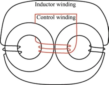
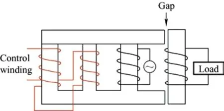
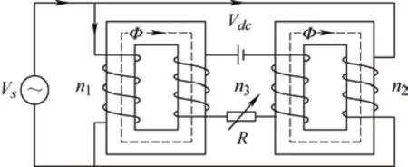
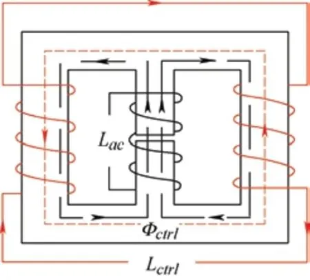
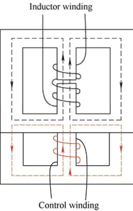
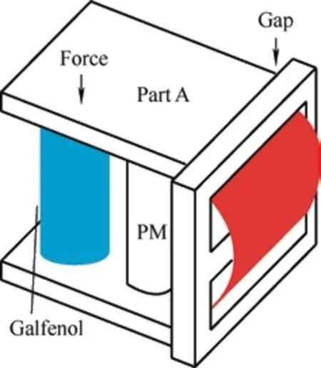
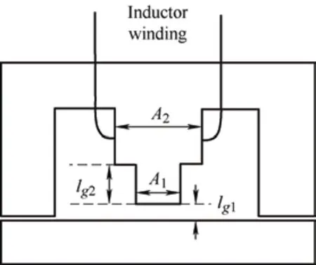
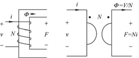
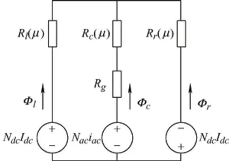
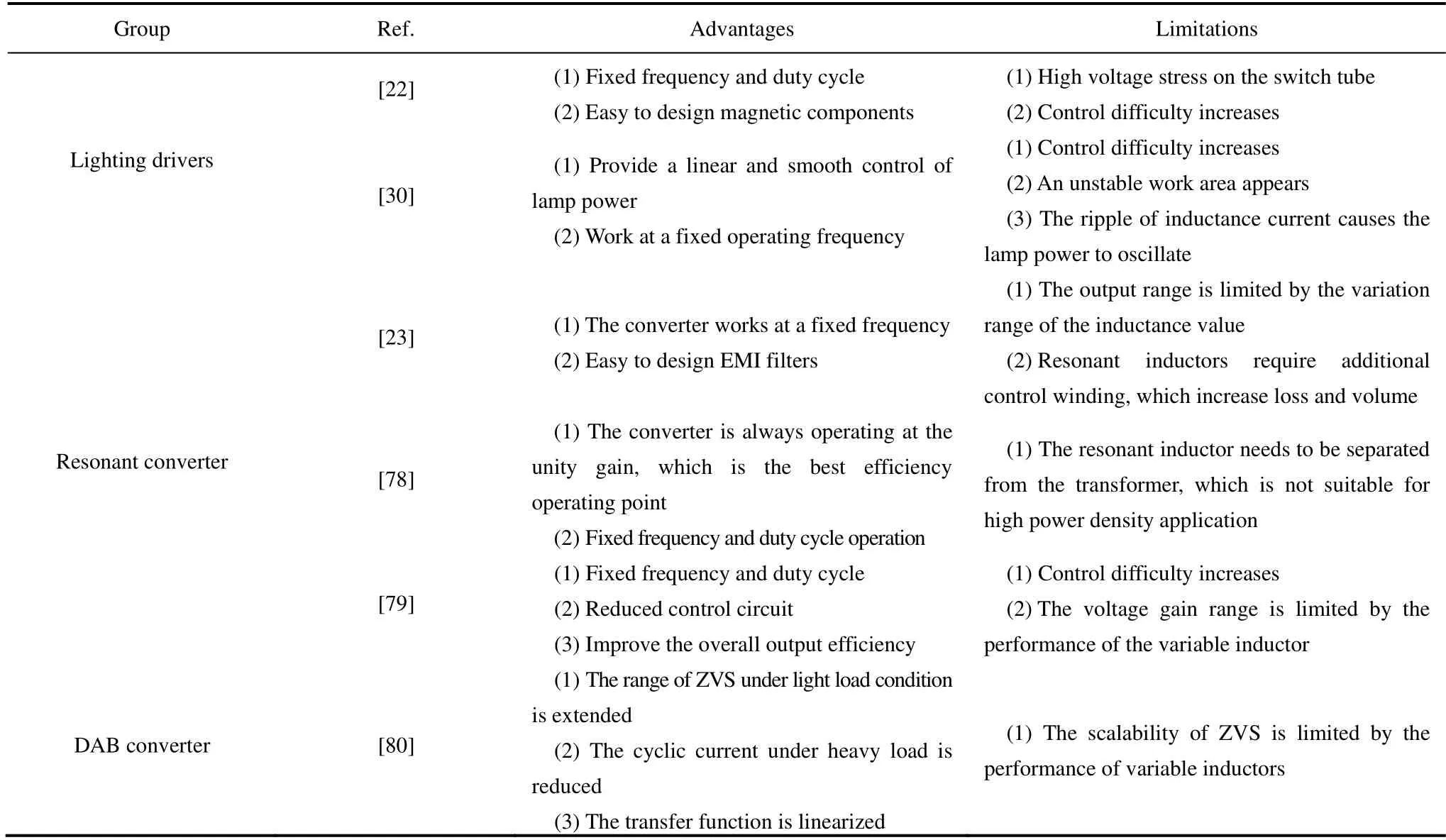
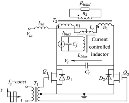
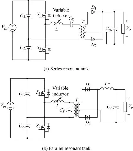
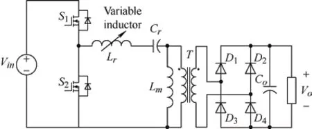
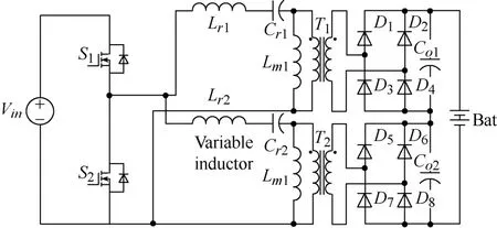
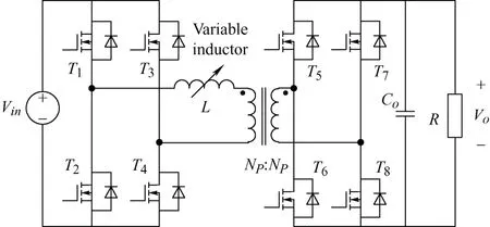
Obviouslyμe<μr,and assuming thatδ According to Eq.(15),the magnetic field intensity can be obtained from theHcin the core and the equivalent airgap magnetic field strength.The core magnetization curve with airgap is a synthesis of the core magnetization characteristics and the airgap magnetization characteristics. As shown in Fig.5,the linearity of the synthesized magnetization curve (i.e.,the dotted line) is much better than that of the material magnetization curve.In other words,the nonlinearity of the core material characteristics is “obliterated” by the gap,with a much larger reluctance.Moreover,μecan be easily modified by changing the length of the air gap.The remaining magnetic fieldBrof the core is significantly reduced owing to the demagnetizing effect of the gap,a property that is very useful for unidirectional magnetization applications as well as for variable inductors. Fig.5 Hysteresis loop Magnetic materials can be divided into hard magnetic materials and soft magnetic materials according to their degree of magnetization.If the hysteresis loop is very wide,i.e.,Hris very large,then a largeBris required to magnetize the material to saturation.To reduce the size of the DC filter inductor in switching power supplies,permanent hard magnetic materials are occasionally used to generate a steady magnetic field that offsets the DC bias.Conversely,soft magnetic materials possess a largeBand low coercivity under the influence of weak external magnetic fields,rendering them easily magnetized and demagnetized.Certain special magnetic materials such as alloys with constant permeability and amorphous alloys are also regarded as soft magnetic materials and are extensively used in switching power supplies. To achieve an extended spectrum of magnetic permeability variation,which is also associated with a range of inductance variations,it is advantageous to select soft magnetic materials. Various soft magnetic materials include alloy magnetic materials,magnetic powder cores,and soft magnetic ferrite materials.Alloys are composed of basic magnetic materials such as iron,nickel,and cobalt,with the addition of other elements.Except for constant-permeability alloys,these materials generally exhibit a high relative permeability,possess a sizableBvalue at saturation,and have a narrow magnetization curve.In particular,the Fe-Ni and Fe-Ni-Mo alloys feature low-frequency magnetization curves close to the ideal rectangular magnetization curve.Cores made of these materials store little energy and are highly suitable for use as transformers and magnetic amplifiers.However,the major drawback of magnetic alloy materials is their very low resistivity,which necessitates their milling into strips to reduce eddy current effects.Powder cores are typically fabricated by mixing a fine magnetic powder with a binder,which is then molded and solidified into a ring-powder metal core for easy use as an inductor or flyback transformer core.Owing to the large amount of nonmagnetic material present in the powder cores,which corresponds to many nonmagnetic distribution air gaps in the core,considerable amounts of energy are stored in these distribution air gaps when magnetized. Some researchers proposed the use of magnetic saturation for variable inductors at an early development stage.A quasi-linear variable inductor was presented by Kislovski[47]in 1987,as shown in Fig.6.The inductor has two circular cores positioned side-by-side with three windings.The control winding encompasses a section of the two adjacent cores,whereas the inductor windings are wrapped around the opposing cores in opposite directions to produce an opposing magnetic flux through the control winding.Consequently,the inductor windings are uncoupled from the control windings,thus isolating the interference from other parameters,which is useful in high-frequency applications.The inductance is generated by creating a magnetic field intensity bias in the core by passing current through the control winding,changing the operating position of the core on the magnetization curve,and altering the permeability of the core along with the inductance[47]. Fig.6 Quasi-linear inductor Based on the same principle,it is possible to modify the inductance by incorporating a control winding into a solitary annular inductor with an air gap.This is outlined in Ref.[48].Furthermore,a quadrupedal magnetic regulator can be derived from Fig.7 in Ref.[49].The regulator consists of four legs,two of which are furnished with a control winding.The third leg encompasses the input winding,and the fourth leg is connected to the load.Vollin et al.[50]conducted an in-depth exploration of this quadrupedal regulator structure and transmuted the model into an inductive model using electromagnetism theory. Fig.7 Four-legged magnetic regulator In power systems,the harmonic distortion and power factor are critical indicators of power quality,and reactive power compensation is important to ensure the voltage stability of a power system.As illustrated in Fig.8,the conventional shunt DC variable reactor modifies the DC current by varying the resistance ofR(Rhas been used for reluctance),consequently,the variable inductance.However,this approach results in a significant number of harmonics.To address this issue,Mu et al.[51]proposed a solution for harmonic cancellation on the primary side.This improvement involves the addition of a harmonic compensation winding powered by a voltage source inverter to each primary winding.The same group of researchers also suggested utilizing ferrite quadrature cores with a comparable design to achieve a variable inductance[52]. Fig.8 Conventional shunt DC variable inductors The most favorable configuration for a variable inductor structure thus far is the three-legged symmetrical structure devised by Medini and Ben-Yaakov[53]which is a double-E core.In this design,the inductor winding is ensconced on the center leg with an intervening air gap,whereas the control windings are wound on the left and right legs in the reverse directions.By directing the current to the bias winding to alter the saturation of some of the cores,the effective permeability of the cores in the center leg was changed,resulting in a modified inductance.As the control windings were uniformly distributed with opposite polarities,the voltages produced by the inductor winding on the side arms were negated,and there was no interaction between the inductor and control windings.Therefore,a small bias is adequate to adjust the effective permeability,and hence,the inductance.The analysis of the topology shown in Fig.9 assumes that the leakage magnetic flux exists solely around the air gap; thus,the control winding does not affect it. Fig.9 Popular three-legged variable inductors Based on the operating principle of variable inductors,several variable-inductor typologies have been proposed by numerous researchers.In Ref.[54],Wolfle and Hurley presented three variations of variable inductors.These components comprise a square-shaped core with an open-air gap and a winding wrapped around the core on the side opposite the gap.There are three types of gaps: the conventional type,a two-step-shaped gap known as the swinging inductor,and a trapezoid-shaped gap with a right-angle bend called the sloped air gap (SAG)inductor.Compared to the fixed airgap inductor,the swinging inductor has a better harmonic performance when one gap is saturated,whereas the other is not.However,when both air gaps are saturated,the same harmonic issues arise as those associated with fixed air gap inductors.A sloped-airgap inductor is a variable inductor designed with a sloped slot that permits smoother transitions in inductance,superior harmonic performance,and reduced inductor size. Ref.[45] presents a variable-inductor topology that employs three E-cores,as shown in Fig.10.Ref.[55]provides the detailed design methodology.The inductor winding is wrapped around the center leg of a dual E-core containing an air gap,whereas the center leg of the remaining E-core houses the control winding.Similarly,the effective permeability of the core was adjusted by the control winding,thereby altering the inductance.The authors incorporated this variable inductor into a single-stage flyback power-factor correction circuit,which showed highly efficient high-power capability and significant harmonic improvement. Fig.10 3E variable inductors proposed in Ref.[45] When ferromagnetic crystals are subjected to an external magnetic field,their dimensions change slightly[56].Upon the removal of the magnetic field,the original dimensions are restored.This phenomenon is known as magnetostriction.The principle of magnetostriction can be employed to obtain a variable inductor,as proposed in Ref.[57].The variable inductors,referred to as Part B in the variable-inductor topology proposed in Ref.[37],consist of two cores made of a magnetostrictive material supported by a cylindrical rod and a permanent magnet (PM) placed in parallel,that is,Part A in Fig.11.The magnitude of the magnetic flux flowing through the rod and the variable inductor was determined by the length of the air gap between the two parts.The range of the inductance variation depended on the distance between the air gaps.When stress is applied to a magnetostrictive material,it induces changes in the magnetic flux within the core,thereby changing the effective permeability of the core of the variable inductor and its inductance value.The application of stress to a magnetostrictive material can be achieved using the method proposed in Ref.[58] without additional power loss.However,because the deformation caused by magnetostriction is very limited,the range of inductance of the variable inductor based on the magnetostriction principle is quite limited. Fig.11 Variable inductors proposed in Ref.[57] In Ref.[59],a new method was proposed for a variable air-core inductor such that the inductance could be modified by changing the position of the sliding aluminum tube.The underlying principle behind the operation of this variable inductor relies on the manipulation of the effective magnetic permeability to regulate the inductance values.This type of inductor has applications in the surge current testing of lightning arresters.Because it can adjust the surge current waveform,it conforms to IEC Standard 62475[60].In this regard,the study in Ref.[32] introduces a variable inductor constructed from a fixed two-stage stepped core and a mobile hollow solenoid coil. Based on Eq.(11),the inductance relies on the permeability,which can be modified by changing the cross-sectional area of the magnetic core.A variable inductor can be created with this principle.In Ref.[61],the researchers introduced a variable inductor by varying the cross-sectional area to achieve different inductance.The proposal in Ref.[61] suggests transforming the traditional EI magnetic core structure’s middle-leg into a stepped magnetic core,as shown in Fig.12.Because of the structure’s stepped formation,the cross-sectional area of the central leg varies and determines the degree of saturation in two areas.When the current flowing through the coil is small,Part1Aand Part2Aare unsaturated.Because of the small air gap in Part2A,the equivalent reluctance of the air gap is also small.Therefore,the inductance mainly depends on the permeability of Part1A.When current flowing through the coil is large,Part1Awill saturate faster due to its smaller cross-sectional area,and the permeability of Part1Awill be close to 0 after saturation.Therefore,the inductance mainly depends on the permeability of Part2A.Therefore,the inductance that needs to change can be obtained by carefully setting the values of Part1Aand Part2A.Because the cross-sectional areas of Part1Aand Part 2Aare designed in advance,the range of change of the inductance is fixed. Fig.12 A variable inductor using a step-gap inductor structure In terms of modeling variable inductors,the initial step involves creating a model for the magnetic core’sB-Hcurve. In 1973,El-Sherbiny[62]proposed an important function,as shown in Eq.(16),which encapsulates five coefficients (a0,1a,a2,a3,anda4) to describe theB-Hcurve shown in Fig.3.These constants provide a more precise and simpler representation of theB-Hcurve for magnetic materials.Subsequently,in 1974,the Brauer model was proposed using three constants to model theB-Hcurve,thereby reducing complexity without sacrificing accuracy[63]. whereαis a positive constant,andais a constant that can be positive or negative. The focal point and challenge in modeling nonlinear inductors is to model the hysteresis phenomena,which requires the calculation of hysteresis parameters from experimental data to effectively utilize nonlinear inductor models.In 1989,Jiles and Thoelke[64]successfully calculated hysteresis loop parameters from a set of experimentally measured magnetization parameters,including non-hysteresis magnetization at the origin,coercivity,residual,and coordinates of the tip of the hysteresis loop.Furthermore,in 1992,the same authors utilized experimentally measured coercivity,remanence,saturation magnetization,initial anhysteretic susceptibility,initial normal susceptibility,and maximum differential susceptibility to thoroughly calculate the parameters describing the hysteresis loop based on the Jilesl-Atherton (JA) model[65]. It is imperative to utilize theB-Hcurve modeling technique to analyze the correlation between electricity and magnetism in variable inductors effectively.This involves accurate modeling of nonlinear inductors. Rumsey[66]first proposed a macroscopic model for saturating inductor structures.His proposed variable inductor model comprises a linear inductor connected in parallel to a nonlinear resistance that changes from a high to a low value when the inductor enters saturation[66].Crangle[67]proposed an improved macroscopic model capable of simulating both saturation and hysteresis.Four ideal diode bridges and a current source were used to simulate hysteresis and saturation,respectively.However,this model is significantly inaccurate owing to the voltage drop caused by the four semiconductor diodes used to connect the current sources,which produce hysteresis effects in a direct or inverted manner.Pei et al.[68]was the first to employ polynomial voltage and nonlinear current control sources in Simulation Program with Integrated Circuit Emphasis (SPICE) to represent the nonlinear characteristics of magnetic components.The model comprises a linear inductor connected in parallel to two controllable current sources.One of them was employed to simulate magnetic saturation,whereas the other simulated the hysteresis.A high-order polynomial law is required to achieve a high accuracy; hence,a complexB-Hcurve-fitting strategy is required to extract the model parameters. Pei et al.[68]devised an intricate macroscopic model for a structure and integrated it into SPICE.When magnetic induction surpasses the saturation threshold,the saturation model is composed of two constant resistors and two diodes connected in parallel to one of the resistors.This hysteresis is created by the depletion capacitance of the two diodes,causing the non-hysteresis curve to shift during the capacitor charging and discharging processes.Regrettably,these capacitors introduce a major issue in this model: they cannot exclusively function under saturation conditions,leading to a false relationship between coercivity and flux density levels.This is because capacitors can be charged at arbitrarily high voltages. In 1994,Hamill proposed a modeling approach in Ref.[69] to represent the inductor using a gyrator capacitance (G-C) model,as shown in Fig.13.TheG-Cmodel emulates the rate of change of the magnetic flux against current according to Faraday’s law and the magnetomotive force and the gyrator’s definition toN-turn coils.The gyration resistance in the gyrator must be in ohms when electrical variables are used instead of magnetic variables.The inductance value at this time can be determined by calculating the effective permeability of the circuit on the right side of the corresponding gyrator.The equation is as follows Fig.13 Gyrator-capacitance variable inductor model The model utilizes permeability and reciprocity of reluctance to represent a magnetic path.The rates of change of the magnetic flux and magnetomotive force are correlated with the current and voltage,respectively,whereas the permeability can be obtained from the capacitance. In Ref.[70],the authors compared the parameters in the traditional reluctance equivalent circuit model with those in the electric circuit model,such as the magnetomotive force and voltage,flux and current,reluctance,and resistance.This analogy,although simple,seems odd because it uses linear resistance (a component that consumes power) to mimic the magnetic core reluctance.Thus,when the impedance model is connected to an external circuit,the linear resistor must be replaced with an inductor,resulting in a new equivalent circuit that bears little resemblance to the original model.At the same time,it ignores some physical phenomena such as magnetic leakage.Therefore,a nonlinear capacitance was used to simulate the saturated core,and the nonhystereticB-Hcurves of the saturated core were obtained using SPICE. It is feasible to acquire a magnetization curve that does not exhibit hysteresis by employing a modeled,controlled,and nonlinear capacitor with a nonlinear transformer and capacitive load based on theG-Cmodel[71].Rozanov and Ben-Yaakov[71]utilized a controlled and nonlinear capacitor to simulate a magnetic energy storage element,which in variable inductors is represented as a core and tested using SPICE.This simulation approach can portray any desired nonhysteresis magnetization curve. Nevertheless,hysteresis is a crucial aspect of the magnetization curve that warrants its inclusion in the saturated-core model for variable inductors.In Ref.[72],a modified JA model was utilized in SPICE to comprehend the dynamic hysteresis phenomenon,with slight changes to the original JA model.A magnetic element subcircuit model with hysteresis was implemented using analog behavioral modeling(ABM).Subcircuits mirroring the JA model were fabricated to simulate the static ferromagnetic hysteresis phenomena.The magnetic core-rate dependency was captured by successive linear dynamic blocks,followed by a static hysteresis block.Both dynamic and static circuits were interlaced to obtain an inductor-transformer model that considers dynamic hysteresis.Finally,simulation and experimental verification were conducted using SPICE,including the primary and secondary side voltages as well as the permeability-frequency curve. Researchers have studied the modeling of nonlinear inductors based on magnetic-core modeling.For instance,Ben-Yaakov and Peretz employed the correlation between electricity and magnetism mentioned in the early sections of Section 2 and factory data from magnetic cores to construct a model of consistent behavior of nonlinear inductors with electrical devices using the computer simulation software SPICE.Nevertheless,this model disregards core losses,temperature changes,and frequency reliance on permeability and does not demonstrate hysteresis effects[73]. Regarding simulation software,there are two distinct approaches for analyzing the behavior of magnetic devices: finite element analysis (FEA) and SPICE-based behavioral models.Using basic and interactive elements (e.g.,cells),it is possible to approximate a system with a finite number of unknowns,which would otherwise be infinite.Solving simulations via 3D modeling techniques often results in highly accurate outputs but incurs significant time costs owing to lengthy processing times.However,PSpice offers the ability to simulate behavior with an ABM,which converts control equations into circuits with controllable voltage and current sources,enabling it to solve general mathematical problems. In Ref.[74],Perdigao et al.conducted simulations on an LC half-bridge resonant inverter featuring a variable inductor,which is the most commonly used electronic ballast topology for fluorescent lamps.Prior to running these simulations,the researchers modeled the behavior of variable inductors using Matlab/Simulink,which proved effective in simulating the soft-start and dimming processes of fluorescent lamps.In 2016,the same group of researchers conducted an FEA simulation of a resonant switchedcapacitor converter (RSCC) with variable inductors.Distinguishing between theG-Cand reluctance models,a variable-inductor design process was proposed with established prototype parameters and inductance variation measured with an impedance analyzer.The parameters found in the core data sheet were used to build a 3D model of the variable inductors,and the hexagonal method presented in Ref.[75] determined winding dimensions and filling factors.The simulation results contained various metrics such as the distribution of flux density and permeability in the core at different magnitudes,inductance variation,waveform of inductor current and flux,and specific variations in inductance over time. In 2016,Alonso et al.[76]proposed a systematic approach for modeling complex magnetic devices using SPICE with magnetic reluctance equivalent circuits,as illustrated in Fig.14.This approach employs three fundamental elements: constant reluctance,variable reluctance,and winding,all of which exhibit electrical and magnetic characteristics.The variable reluctance and winding components were modeled using SPICE.Specifically,the Brauer model[63]was employed to represent variable reluctance.Using these models,a variable inductor model can be constructed within the SPICE framework using electrical devices[76]. Fig.14 Reluctance equivalent circuit with variable inductors of double E-core with an air gap at the center arm Based on the three basic elements of constant reluctance,variable reluctance,and winding,the electrical and magnetic characteristics of any magnetic device can be simulated and directly applied to a specific converter or other electrical circuit with variable inductors[76].The equivalent circuit is shown in Fig.14.Rc,Rl,andRrin the circuit represent the reluctance of the center,left,and right legs,respectively.Their values depend on the DC operating point of the magnetic material and the levels of AC and DC fluxes,which represent the nonlinear behavior of the magnetic material.Rgrepresents the air gap reluctance.Because the air gap did not change after the design of the variable inductors,it was assumed to be constant.The termNx⋅ix(Nx⋅Ix) represents the winding model and electromagnetic interaction within the variable inductor structure.Therefore,the inductance can be calculated based on the reluctance of the different paths in the magnetic circuit,as shown in Fig.14. By employing the explanation of inductance and considering the complete reluctance of the magnetic circuit with respect to the primary winding[77],the varying inductance can be estimated as follows Variable inductors are widely used in various applications owing to their exceptional properties.This section focuses on a review of variable-inductor applications in power converters.The advantages and disadvantages of their application in power converters are presented in Tab.1. Tab.1 Advantages and limitations of variable inductors in different applications In Ref.[53] variable inductors comprising a double E-core have extensive applications in various converters and have the potential for deployment in fluorescent lamp drivers,as indicated by Ref.[77].Typically,three methods are employed to adjust fluorescent lamps: modulation of the DC-link voltage,alteration of the switching frequency,and manipulation of the duty ratio of the inverter,as described in Refs.[13,81]. (1) Vary the DC voltage to allow for linear control over dimming while maintaining a fixed duty ratio and switching frequency.This leads to a smooth switching operation[82]and expands the power range.Nevertheless,the realization of exceptional soft starting remains unachievable. (2) The most widely used control method involves altering the switching frequency.With an increased inverter switching frequency,the inductive impedance of the fluorescent lamp in series switches.Thus,regulating the inductive current enables monitoring of the power of the lamp.Although simple and effective,as the luminescence level decreases,the sensitivity of the fluorescent lamp to the switching frequency increases substantially,generating a nonlinear dimming effect and necessitating the consideration of electromagnetic interference emission problems at high levels. (3) Changing the duty cycle of the inverter enables commands over the pulse width of the square waveform generated at the output.This facilitates control over the average current.However,the application of an asymmetric average current to a fluorescent lamp aggravates the aging process[83].If the duty ratio is not sufficiently large,it can result in a discontinuous inductance current and lead to loss of the soft-switching condition. Voltage-switched resonant inverters are widely used in electronic ballast circuits.The transfer function of the inverter is affected by its switching frequency and the ratio between its switching frequency and resonant frequency[84].In other words,the output can be regulated by altering the resonant frequency; thus,magnetic manipulation can be accomplished using variable inductors.Variable inductance control methods can operate at a constant switching frequency;maintaining a fixed operating frequency during operation has considerable advantages,such as inherent isolation,more linear regulation,constant electrode power,and improved efficiency[31]. In 1994,a current-source resonant inverter was employed as the driver of a high-voltage discharge lamp[22],as shown in Fig.15.Ref.[22] proposed an inductor-controlled current-sourcing push-pull parallel-resonance inverter (IC-CS-PPRI).The resonant network in this inverter was constructed around variable inductors by fixing the operating frequency rather than implementing traditional switching frequency control.Therefore,the inductance can be controlled. Fig.15 Variable inductor-controlled current-sourcing resonant inverter [22] In automotive and railway lighting applications,it is essential to satisfy the specifications set by the International Union of Railways (UIC) and the requirements of affordability,ease of control,and protection.Alonso et al.[27]used a low-cost microcontroller to manage electronic ballasts designed for variable-inductance fluorescent lamps.This enables the soft start and brightness adjustment of the fluorescent lamp in accordance with the regulations set by the UIC.In addition,using this controller enables soft start and safeguards the circuits against overcurrent and voltage instabilities. The most widely used topology for electronic ballast-to-power fluorescent lamps is the half-bridge LC resonant inverter.By utilizing a variable inductor within the half-bridge LC resonant inverter,soft-start and dimming control of electronic ballasts can be realized.Fig.16 illustrates this concept.In Ref.[31],the lamp power is related to the fourth-order exponent of the switching frequency and the second-order exponent of the inductance.This means that control strategies based on the inductance will be smoother than those based on the switching frequency.Thus,a higher efficiency and a more linear dimming curve can be achieved with a constant switching frequency.This ultimately reduces the complexity required for the circuit magnetic device design[31].Half-bridge LC inverters are not the only options for electronic ballasting.In Ref.[30],Perdigao et al.employed variable inductors in four distinct half-bridge resonant inverters: LC,LCC,capacity-impedance inverter(LCC-CII),and CLL.Appropriate selection and design of resonant inverters can help realize linear and smoother regulation of dimming. Fig.16 Magnetically controlled electronic ballasts In addition to the applications in fluorescent lamp drivers,variable inductors have also been employed in various other applications.To improve the power density and efficiency of switching power supplies,resonant and quasi-resonant typologies are extensively employed in switching power supplies[85].Pulse frequency modulation (PFM) is a commonly used adjustment strategy[85-92].By employing this modulation technique,the resonator impedance can be altered by regulating the switching frequency,which adjusts the output voltage.However,resonant converters require a broad range of switching frequencies for modulation when operating over a wide range of input and output voltages.This has resulted in several problems. (1) The converter efficacy can deteriorate owing to the loss of the soft-switching condition at partial switching frequencies. (2) The design requirements of magnetic devices are very stringent owing to excessively large frequency variations. (3) EMI can increase to severe levels owing to the large range of frequency variations[24]. Therefore,narrowing the range of the switching frequency variation and fixing the switching frequency can circumvent the issues outlined above[11]. PSM can effectively satisfy this condition to achieve fixed-switching frequency modulation.PSM is achieved by altering the input voltage of the resonator by adjusting the on-off phase shift angle between the switching tubes.Subsequently,this changes the output voltage.Nevertheless,in the PSM method,a wide-ranging adjustment of the output voltage can cause the lagging switch tube to lose its soft-switching condition,thereby restricting the controllable output voltage range.Moreover,PSM requires additional components,thereby increasing the cost and complexity of the converter. To address the aforementioned issues,Alonso used variable inductors in both series resonant converters and parallel resonant converters without requiring frequency control for switches and reducing the filter size.This technique was established in Ref.[23],as shown in Fig.17.Adjusting the output voltage by implementing a variable inductor as a control parameter is a viable method.However,only 82% efficiency was achieved because the converter did not operate at the resonant frequency.An alternative solution was proposed in Refs.[24,78],where a magnetically controlled LLC resonant converter was developed.By meticulously designing the resonant cavity,both the zero-voltage switching operation of the primary-side switching tube and the zero-current switching operation of the secondary side can be ensured,resulting in a more efficient LLC converter capable of achieving 95% efficiency. Fig.17 Magnetically controlled DC resonant converter A method based on time-domain analysis was proposed in Ref.[78] for the fundamental harmonic analysis (FHA).The FHA is the most common method for analyzing and designing LLC resonant converters,which assumes that only the basic harmonics of voltage and current can provide power.However,in practice,a large error occurs,leading to an amplified error in the parameter design of the converter.Through a time-domain analysis,the LLC resonant converter ensures soft switching of the converter over the entire operating range and limits the root-mean-square (RMS)current of the resonant network to obtain better performance.The magnetically controlled LLC resonant converter is shown in Fig.18. Fig.18 Magnetically controlled LLC resonant converter Among the multistage converters,interleaved converters are often used for applications that require a higher power density and voltage gain owing to their small current ripple and reduced filter size.However,a mismatch of the device parameters between different modules can lead to a severe current imbalance between the modules,resulting in an increased output current ripple.Orietti et al.[93]used variable inductors in two-phase interleaved LLC converters,where the resonant frequency was adjusted by adjusting the value of the resonant inductor of one of the modules to achieve device matching between the two modules.Wei et al.[79]used two LLC resonant converters to achieve an efficient output with constant voltage and current,as shown in Fig.19.The switching tubes on the primary side were shared by two resonant networks,and their outputs were connected in series.A resonant network with a fixed inductance was designed to operate at the resonant frequency.The output power at the resonant frequency accounted for most of the total output power.Another resonant network with a variable inductor was responsible for regulating the output voltage,thereby improving the overall output efficiency. Fig.19 A dual half-bridge LLC resonant converter with magnetic control A conventional dual active bridge (DAB) converter achieves energy transfer by regulating the phase shift(PS) between the two full bridges of the converter.Consequently,the phase-shift angle is instrumental in DAB energy transfer and its operational characteristics. However,for an accurate phase-shift modulation,the transformer turn ratio must match the voltage requirements.A significant mismatch can lead to an increase in the RMS current,inductance,transformer copper loss,and on-off loss of the switching device[94-96].Moreover,when a voltage and current are applied to the transformer through the PS,a circulating current ensues[97].This makes efficient zero-voltage switching impossible even under light loads[98-99].Various alternative modulation schemes are presented in Refs.[96-97,99-101],but these solutions are complex and time-consuming,thereby complicating system control[102]. To resolve these issues,Saeed et al.[80]developed an optimized converter performance model involving variable inductor magnetic control and traditional phase-shift control for a DAB.A magnetically controlled DAB converter is shown in Fig.20.Changes in inductance affect the energy transfer of the DAB.Under light loading conditions,the inductance value is increased to prolong soft-switching operations,while the PS value is increased to prevent “voltage polarity reversal”[98,103].By contrast,under heavy loading conditions,the inductance is reduced to minimize the circulating current,thereby enhancing the DAB efficiency. Fig.20 DAB converter based on variable inductors In summary,the prospects for various inductors in power electronics are significant.These devices can effectively replace most of the conventional inductors in converters.A new level of flexibility and modulation capabilities can be achieved by employing a variable inductance in such circuits[80].Therefore,it is imperative to establish a precise control for variable inductance.Section 2 provides an overview of the distinctive operating principles of variable inductance and highlights that they operate within a nonlinear range in the hysteresis curve,which represents a considerable challenge in maintaining the optimal current. Future studies should focus on simplifying the control mechanism and improving its effectiveness.To achieve this goal,variable inductors can be developed and improved as follows. (1) The variable inductance can be optimized in terms of the structure of the variable-inductor core.For example,in Ref.[104],the authors proposed a new quad-U core structure that was more symmetrical than the U structure.This structure provides a larger inductance range than traditional structures of the same size.Magnetic loss can be reduced by increasing the air gap and AC flux. (2) The variable inductance could be optimized in terms of the magnetic core material.For example,in Ref.[105],the influence of the magnetic core selection on the inductance was studied,particularly the variable inductance working in the nonlinear region.Different magnetic core materials have different nonlinear regions that directly affect the performance of the variable inductance. (3) Power electronics can be used to simulate inductor characteristics.For instance,previous studies on variable capacitors have shown that there is potential for using a gyrator to equate the characteristics of capacitors with those of inductors[106-107].As a nonreciprocal linear two-port device,a gyrator can convert voltage and current signals from one port to another[108].Therefore,by combining the gyrator with a capacitor,the voltage and current characteristics of the inductor can be realized by modulating the capacitance.However,it must be noted that this analog inductance only simulates the relationship between the voltage and current at the inductor port because the gyrator is passive and cannot store energy.Thus,they cannot replace power inductors in energy transfer and conversion.Hence,it is necessary to study the topological structure of power electronic devices and attempt to replace their magnetic components. (4) Variable inductors can be optimized to reduce their size.For example,previous studies on planar magnetic components have shown that planar inductance can be realized by placing the inductance on the PCB to reduce the volume and increase the power density[109-111].However,the design of planar magnetic elements is relatively complicated,and their eddy current effect of planar magnetic elements increases significantly with increasing frequency.In addition,at a higher frequency,the skin effect,proximity effect,and end effect of the winding will also increase,and the airgap diffusion flux loss of the planar inductor will be significant.Multiplayer stacked winding results in a larger winding capacitance,and PCB winding essentially has a larger surface area than traditional wire winding,which further increases the winding capacitance[112-113].Therefore,the magnetic materials and structures of the planar magnetic elements must be further studied and optimized. Therefore,variable inductors are expected to play a key role in future power converters,and further research on variable inductors should be conducted to meet the growing demands of various industrial applications. The overarching objective of this study was to examine and review the operational principles of variable inductors.Furthermore,it briefly examines the basic electromagnetism and magnetization processes.Over the past century,numerous researchers have conducted extensive studies on varied inductance topologies of magnetic cores.These studies predominantly focused on modifying the magnetic saturation of the magnetic core by regulating the current and altering the reluctance by modifying the length of the magnetic core and cross-sectional area. Currently,variable inductors,particularly PFCs,have gained great popularity for regulating the output voltage or power of power converters.These inductors can facilitate the soft-start and power regulation of fluorescent lamps,optimize the resonant converter performance,and improve the efficiency of DAB and other similar fields.Nonetheless,achieving precise control over the variable inductance remains a significant obstacle that impedes its wide application in converters.This review guides future research in this field.
2.3 Core materials
3 Typologies and control of variable inductors
4 Various models of variable inductors
5 Applications of variable inductors in power converters
5.1 Lighting drivers with variable inductors

5.2 Resonant converter with variable inductors
5.3 Dual-active-bridge converter with variable inductors
6 Future work and potential development
7 Conclusions
杂志排行
Chinese Journal of Electrical Engineering的其它文章
- Modified Sliding Mode Observer-based Direct Torque Control of Six-phase Asymmetric Induction Motor Drive
- A Multi-scale Smart Fault Diagnosis Model Based on Waveform Length and Autoregressive Analysis for PV System Maintenance Strategies*
- TSKARNA-norm Adaption Based NLMS with Optimized Fractional Order PID Controller Gains for Voltage Power Quality
- Quantitative Comparison of Modular Linear Permanent Magnet Vernier Machines with and without Partitioned Primary*
- Fast Solution Method for the Large-scale Unit Commitment Problem with Long-term Storage*
- Value Evaluation Method for Pumped Storage in the New Power System*