Z-configuration A-DA'D-A Type Acceptor with Thermal Annealing Induced High Open Circuit Voltage
2023-10-10ZHANGLitingQIUDingdingZHANGJianqiLYUKunWEIZhixiang
ZHANG Liting, QIU Dingding, ZHANG Jianqi, LYU Kun, WEI Zhixiang
Z-configuration A-DA'D-A Type Acceptor with Thermal Annealing Induced High Open Circuit Voltage
ZHANGLiting1,3,4#, QIUDingding1,3,4#, ZHANGJianqi1,2,3, LYUKun1,2,3,4*, WEIZhixiang1,2,3,4*
(,,,,100190,;,101408,)
The development of organic solar cells(OSCs) is approaching the industrial production gradation. In addition to high power conversion efficiency(PCE), it is critical to develop new active layer materials with high open circuit voltage(OC) and to reduce non-radiative recombination loss. Here,“Z”-configured naphtho[1,2-c∶5,6-c']bis[1,2,5]thiadiazole(NT) nuclear A-DA'D-A receptor(ZNT) with a high lowest unoccupied molecular orbital (LUMO) energy level, is developed based on the electron-withdrawing unit(A) -electron-donating unit(D) combination of A-DA'D-A type acceptor Y6, which emerges a “Z” configuration and achieves a reduction in the non-radiative recombination loss of the device with D18 as the donor by increasing the annealing temperature. In order to investigate the difference between this phenomenon and the general phenomenon ofOCreduction by thermal annealing, the D18∶Y6 system was prepared as a reference. By increasing the temperature of thermal annealing, the Urbach energy(U) of D18∶Y6 is elevated,and the non-radiative recombination loss is increased, thus, theOCis consistently reduced. Surprisingly, the increase of the thermal annealing temperature decreases theUof D18∶ZNT and effectively decreases the non-radiative recombination loss, therefore, theOCshows an unexpected increase.OCincreases from 0.950 V under the unannealed condition to 0.963 V(80 ℃), 0.993 V(100 ℃), and even 0.995 V(110 ℃). Combining the trends of increasing electron mobility with decreasing crystal coherence length(CCL) of the pure acceptor ZNT when the annealing temperature increases, it is inferred that the reduction of energetic disorder is a result of the augmented order of the acceptor ZNT. In addition, the ZNT has a higher LUMO, higher occupied molecular orbital(HOMO) energy levels and band gap than Y6, higher planarity of structure, and lower device exciton dissociation, making the PCE of the ZNT-based devices lower than that of the Y6-based devices. The present work is potentially instructive for the development of A-DA'D-A type acceptors and provides a material design direction for the future development of high-OCOSCs that avoids the phenomenon of the reduction ofOCby thermal annealing.
Non-fullerene acceptor; Non-radiative recombination loss; Urbach energy; High open circuit voltage organic solar cell
1 Introduction
Organic solar cells(OSCs) have attached widespread attention for their excellent flexibility, lightweight, good solution processing, and ability to prepare translucent devices[1—6]. With the development of active layer materials, device optimization, the power conversion efficiency(PCE) of OSCs has been promoted greatly[7].At present, the PCE of single-binary OSCs has exceeded 19%[8,9], and such a high PCE has reached the threshold of industrial application. Among them, the development of acceptor materials directly propels the qualitative leap of device performance, especially the non-fullerene acceptors(NFAs) play a decisive role[10]. Zhan’s group first designed and synthesized IEIC using electron-withdrawing units(A) and electron-donating units(D), which pioneered the A-D-A type fused ring NFAs[11]. A series of A-D-A type NFAs were subsequently developed by researchers, such as ITIC and IT-4F. The value of PCE increased significantly from 6.4% to 14.4%[12—14]. In parallel with the development of A-D-A type NFAs, Zou’s group innovatively developed A-DA'D-A fusion ring NFAs, which exhibit more efficient intramolecular charge transfer due to the addition of an electron-withdrawing unit in the central core, and also present a C-configuration completely different from the Z-configuration of the A-D-A acceptor. From BZIC with a five-number fused rings, to Y1 with expanded conjugation, and Y6 with stronger electron-withdrawing capacity core benzo[c][2,1,3] thiadiazole(BT), the device PCE was substantially increased from 6.3% to 13.42%, and an unprecedented 15.7%[15—17].
Researchers have made every effort to discover the reasons for the superior performance of Y-series molecules. Zou’s group[18]developed Y18 on the basis of Y6. The reduced electron-withdrawing ability of the central core allowed the lowest unoccupied molecular orbital(LUMO) energy level of Y18, and the energy loss was reduced. Li’s group[19]designed and synthesized SN6-2Br in the linear fused Z-configuration and BTP-2Br in the C-configuration. BTP-2Br with a strong electron-withdrawing core exhibits a slightly higher LUMO energy level, a lower highest occupied molecular orbital(HOMO) energy level and a larger band gap. Meanwhile, BTP-2Br possesses better planarity, and exhibits a lower exciton dissociation. Yi’ group[20]investigated the effect of electron-withdrawing capabilities of the core and linear fused Z-configuration as well as angular fusion mode C-configuration on Y6 molecule. The results of the study indicate:(1) from the-BP to Y6 which are all in angular fusion mode C-configuration, the electron-withdrawing ability of the central core is enhanced, the molecular planarity is reduced, leading to the decrease of LUMO and HOMO energy levels and enhanced exciton dissociation;(2) from-BP of linear fused Z-configuration to-BP of angular fusion mode C-configuration, high planarity disappears, leading to higher LUMO energy level, but lower HOMO energy level and enhanced exciton dissociation. Overall, from Y6 to-BP, the electron-withdrawing ability decreases and the configuration changes completely, both LUMO and HOMO increase. Corresponding to the changes in Y6 and Y18, the results are in good agreement with conclusion (1). It is worth mentioning that for SN6-2Br and BTP-2Br, the enhancement of the electron-withdrawing capacity shows the results of (2) instead, which proves from the side confirmation that the effect of the configurational change is greater than the change of the electron-withdrawing capacity. Simultaneously, the development history shows that the open circuit voltage(OC) has also become a key factor limiting the further improvement of PCE. Where the energy loss comes from two aspects: the driving force of exciton dissociation and the non-radiative recombination[21,22]. The low Urbach energy(U) implys a weak non-radiative recombination[23]. Wei’s group[24]synthesized Qx-1 and Qx-2 with a rigid structure quinoxaline(Qx). The non-radiative recombination loss was greatly reduced due to the reduced molecular vibration of the rigid structure. An inevitable part of device fabrication is the thermal annealing(TA) to optimize the active layer morphology, but this process generally reduces the value ofOC[25]. Therefore, the development of active layer materials whoseOCis not affected by thermal annealing is very critical and important.
In this work, the strong electron-withdrawing group, naphtho[1,2-c∶5,6-c]bis[1,2,5]-thiadiazole(NT), which has a stronger electron-withdrawing ability than BT and has an expanded conjugated structure[26,27], was used to replace BT in the Y-series molecule to explore the effect of the strong electron- withdrawing core onOCof the devices. The A-DA'D-A acceptor material 2,2'-[(2Z,2'Z)-{[8,16-bis(2- butyloctyl)-5,13-diundecyl-8,16-dihydro-[1,2,5]thiadiazolo[3',4'∶4,5]thieno[2'',3''∶4',5']thieno[3', 2'∶2,3]indolo[7,6-g][1,2,5]thiadiazolo[3,4-e]thieno[2',3'∶4,5]thieno[3,2-b]indole-6,14-diyl]bis (methaneylylidene)}bis(5,6-difluoro-3-oxo-2,3-dihydro-1-indene-2,1-diylidene)]dimalononitrile(ZNT), which has a high planarity by the linear fused Z-configuration, was designed and synthesized, and the device with D18 exhibited a trend of elevatedOCwith increasing annealing temperature[28]. TheOCof the device was 0.950 V under unannealed conditions, and gradually increased to 0.963 V(80 ℃), 0.993 V(100 ℃), and 0.995 V(110 ℃). As a comparison, D18∶Y6 -based devices were also prepared. TheOCof the D18∶ Y6-based devices decreased continuously to 0.843 V(as-cast), 0.836 V(80 ℃), 0.832 V(100 ℃), and 0.824 V(110 ℃). TheUof the D18∶Y6 showed an increasing trend, and the energy loss test also exhibited a corresponding enlargement in the non-radiative recombination loss. TheUof the D18∶ZNT showed a conversely decreasing trend, indicating that the device energetic disorder decreases, which implies the reduction of non-radiative recombination loss, as evidenced by the energy loss test. The simultaneous rising trend in electron mobility indirectly implies that the acceptor ZNT is gradually ordered at the elevated annealing temperature. This is supported by the change in crystal coherence length(CCL) of the pure acceptor ZNT film. In addition, the higher LUMO, HOMO energy level and band gap of ZNT compared to Y6 and the lower exciton dissociation than the D18∶Y6-based device also indicate that the influence of configuration is greater than that of the electron-withdrawing capacity of the central core[17,29]. This work demonstrates that the reduction ofOCby thermal annealing can be avoided, and even theOCvalue can be elevated, which is a reference for the future development of high-OCdevices.
2 Experimental
2.1 Materials and Instruments
Naphtho[1,2-c∶5,6-c']bis([1,2,5]thiadiazole)(Monomer 1) and tributyl(6-undecylthieno[3,2-b] thiophen-2-yl)stannane(monomer 4) were purchased from Shanghai Acmec Biochemical Co., Ltd. Trifluoroacetic acid(TFA), dibromohydantoin(DBDMH), trifluoromethanesulfonic acid(CF3SO3H), tetrakis(triphenylphosphine)palladium[Pd(PPh3)4] and triethyl phosphite[P(OEt)3] were purchased from Beijing Innokai Technology Co., Ltd. and J&K Scientific. Toluene was distilled from drying agents before they were used. All other reagents were purchased from commercial channels and without further purification.
Autoflex MAX, Bruker Corporation, Switzerland; Bruker microflex MALDI-TOF mass spectrometer, Bruker Corporation, Switzerland; Buker Avance 400 Nuclear Magnetic Resonance spectrometer(NMR), Bruker Corporation, Switzerland; Dimension ICON multimode M8 atomic force microscope(AFM), Bruker Corporation, Switzerland; Tecnai G2 F20 U-TWIN Transmission Electron Microscope(TEM), FEI Company, America; Shimadzu UV-3600 Ultraviolet-Visible near infrared spectrophotometer(UV), Shimadzu Corporation, Japan; EG&G Princeton Applied Research VMP3 workstation, Ametek Group, America; Solar simulator(SS-F5-3A), FETOS-QE-3011 and integrated system PECT-600(Energy loss), Sheng Yan Electronic Technology(shanghai) Co., Ltd.; Keithley 2400, Tektronix Co., Ltd., America.
2.2 Material Synthesis
The synthesis route is shown in Scheme 1.

Scheme 1Synthetic routes of ZNT
Monomer 1 of 105 mg(0.43 mmol) was dissolved in 15 mL of TFA and the solution was stirred at 50 ℃. 270.5 mg(2.2 mmol) of DBDMH was gradually added three times at dark. The solution was stirred for 2 h and then cooled down to obtain the solid 5,10-dibromonaphtho[1,2-c∶5,6-c']bis([1,2,5]thiadiazole)(monomer 2) crude product by filtration.1H NMR(400 MHz, CDCl3),: 9.14(s, 2H). The crude product of the previous step was dissolved in 3 mL of trifluoromethanesulfonic acid at 0 ℃ and then fuming nitric acid was dropwise added, the solution was warmed to 50 ℃ and stirred overnight. After cooling down, the solution was poured into ice water, and NaOH was added until the solution was neutral. The solid was collected by filtration. The preliminary product was recrystallized in ethanol to obtain the crude product 5,10-dibromo-4,9-dinitronaphtho[1,2-c∶5,6-c']bis([1,2,5]thiadiazole)(monomer 3). 4,9-dinitro-5,10-bis (6-undecylthieno[3,2-b]thiophen-2-yl)naphtho[1,2-c∶5,6-c']bis([1,2,5]thiadiazole)(monomer 5) was synthesized by Stille coupling of 381 mg(0.78 mmol) of monomer 3 and 1.81 g(3.1 mmol) of monomer 4 under the catalysis of 80 mg(0.07 mmol) Pd(PPh3)4. The solution was stirred at 110 ℃ overnight under nitrogen protection with 25 mL of toluene as solvent. The crude product was extracted by dichloromethane twice. Pure product 5(70%, 573 mg) was obtained by column chromatography using a mixture consisting of PE and dichloromethane in a volume ratio of 1∶5 as eluent. MALDI-TOF,/: 919.1H NMR(400 MHz, CDCl3),: 7.85(s, 2H), 7.19(s, 2H), 2.82—2.78(t, 4H), 1.84—1.77(m, 4H), 1.27(s, 32H), 0.90—0.88(m, 6H).
Compound 5 of 573 g(0.62 mmol) and 2 mL of triethyl phosphite were dissolved in 10 mL-dichlorobenzene(-DCB). The solution reacted in a microwave reactor at 220 W, 180 ℃ for 2 h. After cooling down, the solution was added dropwise into 200 mL of methanol and kept cold overnight. After removing the solvent, the red residue was added into a three-necked round bottom flask. 414 mg(1.27 mmol) of Cs2CO3, 253 mg(1.52 mmol) of KI and 10 mL of DMF were added, and the mixture was deoxygenated with argon for 15 min. 5-(Bromomethyl) undecane of 316 mg(1.27 mmol) was added. The mixture was refluxed at 90 ℃ overnight under nitrogen protection. The solution was extracted by dichloromethane twice. Next, purification was conducted by silica gel column using a mixture consisting of PE and dichloromethane in a volume ratio of 1∶1 as eluent to give monomer 8,16-bis(2-butyloctyl)-5,13-diundecyl-8,16-dihydro-[1,2,5]thiadiazolo[3',4'∶4,5]thieno[2'',3''∶4',5']thieno[3',2'∶2,3]indolo[7,6-g][1,2,5]thiadiazolo[3,4-e]thieno[2',3'∶4,5]thieno[3,2-b]indole(monomer 6)(11%, 80 mg). MALDI-TOF,: 190.1H NMR(400 MHz, CDCl3),: 8.10(s, 2H), 4.11—4.09(d, 4H), 1.53(s, 2H), 1.34—1.29(m, 72H), 0.92—0.88(m, 18H).
Monomer 6 of 80 mg(0.068 mmol) was dissolved into 10 mL of 1,2-dichloroethane in a three-neck flask. The solution was flushed with nitrogen at 0 ℃ for 30 min. Then, 0.25 mL of POCl3was added dropwise to the solution, and the solution temperature was restored to room temperature by adding 0.25 mL of DMF. Next, the solution was reacted at 80 ℃ overnight under nitrogen protection. Washed with saturated salt water and dichloromethane. The solvent was removed under reduced pressure. The crude product was subsequently purified by column chromatography on silica gel using a mixture of PE and dichloromethane in a volume ratio of 1∶2 as eluent to afford 8,16-bis(2-ethylhexyl)-5,13-diundecyl-8,16-dihydro-[1,2,5]thiadiazolo [3',4'∶4,5]thieno[2'',3''∶4',5']thieno[3',2'∶2,3]indolo[7,6-g][1,2,5]thiadiazolo[3,4-e]thieno [2',3'∶4,5]thieno[3,2-b]indole-6,14-dicarbaldehyde(compound 7)(88%, 75 mg). MALDI-TOF,:1246.1H NMR(400 MHz, CDCl3),: 10.18(s, 2H), 4.32—4.29(m, 2H), 3.25—3.22(m, 4H), 1.28—1.24(m, 72H), 0.89—0.86(m, 18H).
Monomer 7 of 110 mg(0.088mmol) and 202 mg(0.88 mmol) of 2-(5, 6-difluoro-3-oxo-2,3-dihydro-1-inden-1-ylidene)malononitrile were dissolved into 20 mL dry chloroform in a three-neck flask. The solution was flushed with nitrogen for 20 min. After 0.5 mL of pyridine was added, the mixture was stirred at 65 ℃ for 12 h. After cooling to room temperature, the reaction mixture was poured into water and extracted several times with chloroform. Then the solvent was removed under reduced pressure, and the crude product was purified by column chromatography on silica gel using a mixture of PE and dichloromethane in a volume ratio of 1∶2 as eluent to yield ZNT(8, 34%, 50 mg). MALDI-TOF,: 1671.1H NMR(400 MHz, CDCl3),: 8.77(s, 2H), 8.44—7.40(m, 2H), 7.55—7.51(m, 2H), 3.08(t, 4H), 2.25—2.01(m, 2H), 1.82Ⅰ1.26(m, 72H), 0.87—0.84(m, 18H).
2.3 Device Fabrication
The devices were fabricated with a conventional structure of indium tin oxide(ITO)/poly(3,4-ethylenedioxythiophene)∶poly(styrenesulphonate)(PEDOT∶PSS)/D18∶acceptor/2,9-Bis(3-{[3-(dimethylamino) propyl]amino}propyl)anthra[2,1,9-def∶6,5,10-d'e'f']diisoquinoline-1,3,8,10(2,9)-tetraone(PDINN)/Ag. The glass substrate coated with ITO was cleaned by water with detergent, water, acetone, and isopropanol in an ultrasonic bath for 30 min; then treated with UV-ozone for 15 min. The PEDOT∶PSS was deposited by spin-coating under 3500 r/min for 30 s on top of the ITO substrate with thermal annealing for 25 min at 150 ℃. The substrate was transferred to the glove box next. Donor and acceptor materials were dissolved in chloroform(CF) with a total concentration of 10 mg/mL[(D18)∶(Y6)=1∶1.6,(D18)∶(ZNT)=1∶1.0] and then stirred at 50 ℃ for 60 min. The blend solution was spin-coated at 3000 r/min for 30 s to form a thin film on the substrate. Thermal annealing at different temperatures for 10 min was utilized to optimize the morphology of the active layer. Then, PDINN was spin-coated onto the top of the active layer as an electron transport layer at 2000 r/min for 30 s. Finally, 160 nm of Ag was deposited onto the active layer to form a back electrode. The electrodes were deposited under a high vacuum(1×10⁻⁴Pa), and the effective area was defined by masks of 4 mm2.
2.4 Methods and Devices Characterization
UV-Vis spectra and solution UV-Vis absorption spectra at elevated temperatures were obtained using chloroforms as solvent. All the film samples were spin-cast on quartz substrates.
The electrochemical cyclic voltammetry analysis was carried out with a standard three-electrode electrochemical cell, using Ag/AgCl as the reference electrode, a Pt plate as the counter electrode, a Pt plate on which acceptor was drop-cast from CHCl3solution to form thin film as the working electrode, 0.1 mol/L tetrabutylammonium phosphorus hexafluoride(Bu4NPF6) acetonitrile solution as an electrolyte at a scanning rate of 50 mV/s.
Themeasurements were performedthe solar simulator along with AM 1.5 G spectra, whose intensity was calibrated by the certified standard silicon solar cell at 100 mW/cm2.
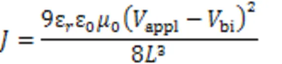
Space charge limited current(SCLC) method was used to measure the charge mobility of the blend active layer. The structure of ITO/PEDOT∶PSS/active layer/MoO/Ag was adopted for hole-only devices. The structure of ITO/ZnO/active layer/PNDIT-F3N/Ag was used for the electron-only device. The charge mobility was calculated according to the MOTT-Gurney equation:

3 Results and Discussion
3.1 Density Functional Theory Calculation
The configuration of ZNT is inevitably presented as “Z-shape”(Fig.1), and the three- dimensional(3D) structure is obtained from the density functional theory(DFT) calculation at the B3LYP/6-31+G(,) level carried out with Gaussian 09 revision D.01[30]. The side view shows that ZNT has a fairly high planarity, with an N—C—C—C dihedral angle of only 7.8°, which is much smaller than the N—C—C—N dihedral angle of Y6(-17.5°)[17], while the NT unit is twisted due to the presence of branched alkyl chains, with an N—C—C—C dihedral angle of 11°(Fig.2).

Fig.1 Chemical structures of Y6 and ZNT
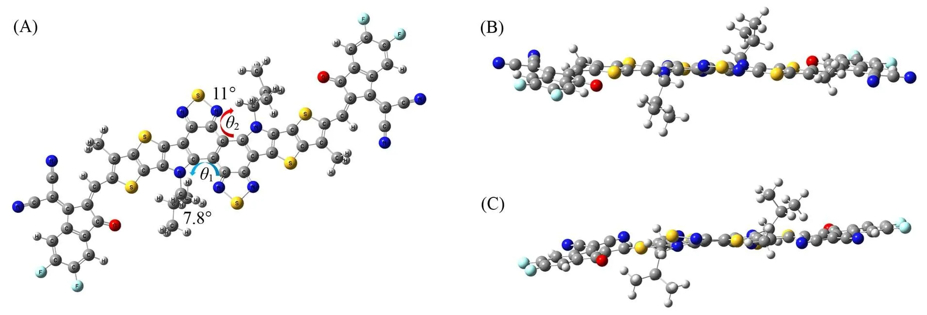
Fig.2 Top view(A) and side views(B, C) of different perspectives of the optimized geometry of ZNT computed with B3LYP/6⁃31+G(d, p) level
3.2 Optical and Electrochemical Properties

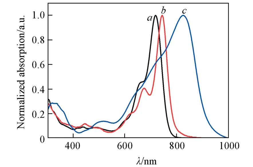
Fig.3 Normalized UV⁃Vis absorption spectra of ZNT in solution(a) and at neat film state(b) and Y6 at neat film state(c)

Fig.4 Temperature⁃dependent UV⁃Vis absorption spectra of ZNT in chloroform

Fig.5 CV curves of ZNT(A) and energy levels of D18, Y6 and ZNT(B)
3.3 Device Performance
The conventional structure of ITO/PEDOT∶PSS/D18∶Acceptor/PDINN/Ag was used to explore device photovoltaic performance(Table 1). During the optimization process, the parameter of the two systems showed completely different phenomena: as the annealing temperature increased, theOCof D18∶Y6 continued decreasing, as is common with reported devices, whileSCgradually increased and Fill factor(FF) decreased. The complex changes led to a slight floating of the PCE values; while theOCof D18∶ZNT continued to boost with an increment of 0.045 V,SC, FF and PCE all showed a trend of increasing and then decreasing. The external quantum efficiency(EQE)-integratedSCfor D18∶Y6 and D18∶ZNT devices at different annealing temperatures were 24.96 and 12.71 mA/cm2(As-cast), 25.25 and 13.80 mA/cm2(80 ℃), 25.40 and 11.31 mA/cm2(100 ℃) and 25.60 and 10.65 mA/cm2(110 ℃)(Fig.6). In addition, the trend of EQE is consistent with that ofSCchange. The errors betweenSCvalues calculated from EQE curve integration and actual measurements are all within 5%.
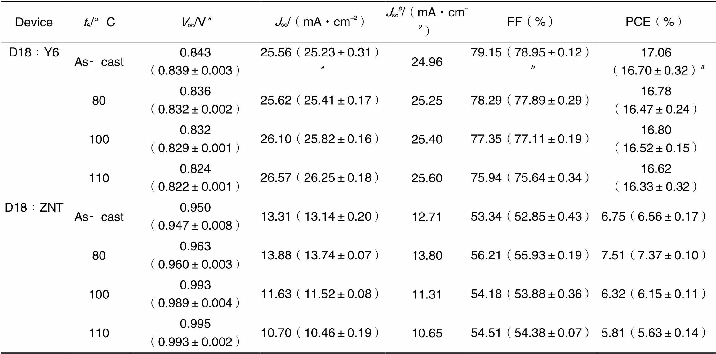
Table 1 Photovoltaic performance of the devices under different annealing temperatures(tA)
Average values are based on 5 devices;the calculatedscvalues from the EQE curves.

Fig.6 J⁃V curves(A, D), EQE curves(B, E) and dependence of Jph on Veff(C, F) of the D18∶Y6(A—C) and D18∶ZNT(D—F) devices under different annealing temperatures
To further demonstrate the unique phenomenon ofoc increment in D18∶ZNT system as annealing temperature increased, the exciton dissociation, charge collection processes, and charge recombination under different temperature conditions are evaluated using the dependence of photocurrent density(ph) on the effective voltage(eff)(Fig.6) and light intensity depending on the deviceSCandOC. Usually,phis defined as the current density difference under illumination and dark,effis defined as the difference between the voltage0whenph=0 and the applied voltageappl. Assuming that all excitons separate into free charges at an adequately higheffand the photo-generated current can reach the maximum saturationsat. The exciton dissociation(diss) is the ratio ofph(under short-circuit conditions) tosat, and the charge collection efficiency(coll) is the ratio ofphunder maximum power output conditions tosat[33,34]. It is easy to see that both parameters of D18∶ZNT show a trend of boosting and then decreasing according to the change of annealing temperature from low to high, withdissof 91.95%, 93.61%, 91.87%, and 90.23%, andcollof 71.17%, 72.66%, 72.06% and 68.15%, respectively. In contrast, the two parametersdiss(98.69%, 98.65%, 98.59%, 98.72%) andcoll(90.58%, 90.27%, 89.62%, 89.82%) of D18∶Y6 were largely unaffected by the annealing temperature and were much higher than those for D18∶ZNT. This finding is consistent with the results of thedisschange by the configurational change studied by Yi[20]. Combining molecular planarity, UV-Vis absorption spectra and energy level variations, it can be effectively demonstrated that the configurational influence is greater than the effect of the electron-withdrawing ability of the central core on the molecular optical and electrochemical properties and device performance.
3.4 Charge Characterization
Fig.7(A) and (B) show the charge recombination and transport properties of D18∶ZNT. The correlation betweenSCand light intensity(light) can be expressed by the formula ofSC∝(light)α. For the devices under different temperature annealing,are 1.11, 1.10, 1.12 and 1.11, respectively, with a small difference close to 1, indicating that the annealing temperature has a very weak effect on the charge recombination. Thelightdependence ofOCis given byoc∝(BT/) lnlight(kis the Boltzmann constant,is the absolute temperature, andis the elementary charge). The slope values for different annealing temperatures are 1.37, 1.48, 1.45, and 1.41BT/q, respectively(Fig.7). The trend of the slope change is expectedly the same as the inclinations ofSCand FF variations, indicating that the trap-assisted recombination decreases under low-temperature(80 ℃) annealing and intensifies under high-temperature(100, 110 ℃) annealing. Consequently, a low-temperature annealing treatment is beneficial to the enhancement ofSCand FF for D18∶ZNT-based devices, but a high-temperature annealing treatment has the opposite influence.

Fig.7 Jsc(A) and Voc(B) dependence on light intensity, hole mobilities(C) and electron mobilities(D) curves of D18∶ZNT⁃based devices under different annealing temperatures
SCLC method was applied to characterize the charge transport properties of D18∶ZNT[Fig.7(C) and (D)]. The hole(h) and electron(e) mobilities of as-cast device are 1.63×10⁻⁵and 3.28×10⁻⁵cm2∙V-1∙s-1, the value ofh/eis 0.5. The device under 80 ℃ annealing exhibited lowerhof 1.59×10⁻⁵cm2∙V-1∙s-1and highereof 3.31×10⁻⁵cm2·V-1·s-1, the value ofh/eis 0.48, lower than that of the as-cast device. The device under 100 ℃ annealing exhibited decreasedhof 1.53×10⁻⁵cm2∙V-1∙s-1and increasedeof 3.37×10⁻⁵cm2∙V-1∙s-1, the value ofh/ekeeps decreasing to 0.45. The device under 110 ℃ annealing exhibited the lowesthof 1.50×10⁻⁵cm2∙V-1∙s-1and the highesteof 3.68×10⁻⁵cm2∙V-1∙s-1, the value ofh/edirectly decreased to 0.41. It is worth mentioning thathhas been in a decreasing trend, whilee, like theOCvariations, has been enlarging and is much higher thanh. The equalization of the two parameters with opposite trends leads toSCshowing a result of first rising and then falling. This also tentatively implies that the increase in annealing temperature leads to a more orderly acceptor ZNT, thus a more efficient electron transport.
3.5 Energy Loss

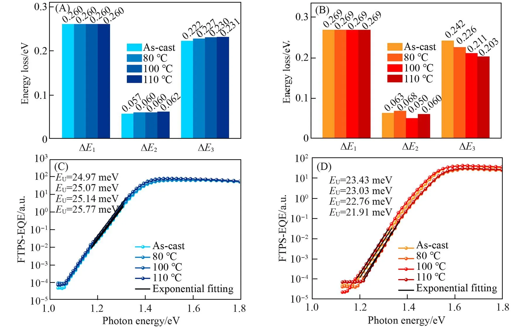
Fig.8 Energy loss(A, B) and FTPS⁃EQE spectra(C, D) for the D18∶Y6(A, D) and D18∶ZNT(B, D) devices under different annealing temperatures
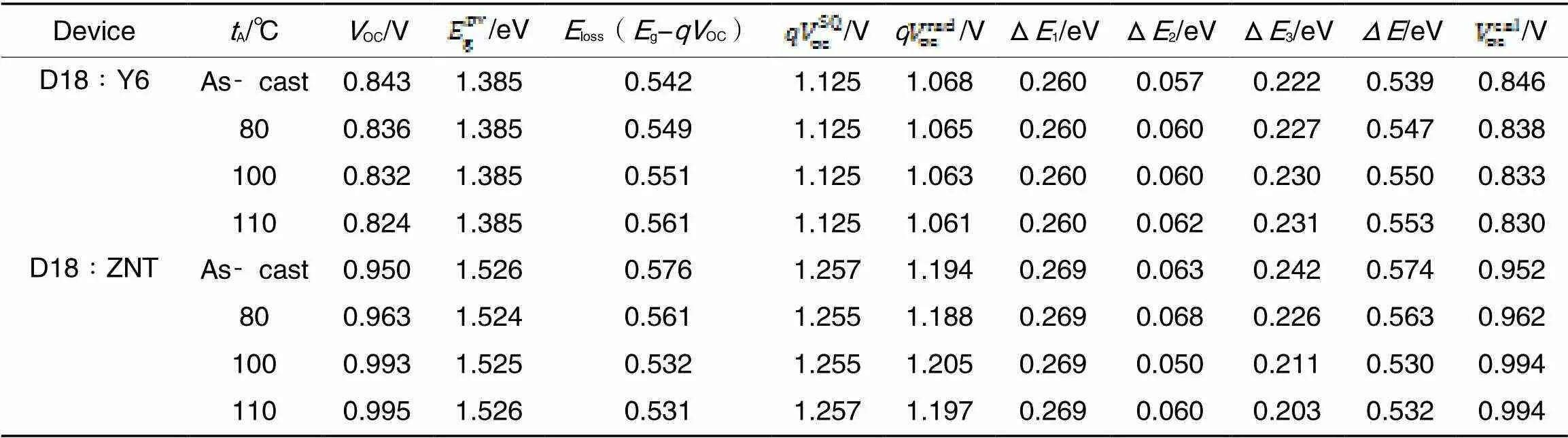
Table 2 Energy loss of the devices under different annealing temperatures
3.6 Morphology and Molecular Orientation
Atomic force microscopy(AFM) and grazing incidence wide-angle X-ray scattering(GIWAXS) were used to characterize the morphology, the molecular crystallinity and orientation of the active layer under increasing annealing temperature(Fig.9). The values of the root-means-square(RMS) roughness(q) of the D18∶ZNT at different annealing temperatures are 1.81, 1.73, 1.87 and 2.15 nm. The variation trend is consistent with that ofSC, FF and PCE. It means that low-temperature annealing can improve the aggregation of the active layer, which facilitates charge collection, while high-temperature annealing has the contrary influence. From 2D GIWAXS patterns, it can be seen that when the annealing temperature varies, the diffraction patterns of the D18∶ZNT keep the same, exhibiting a strong diffraction ring in thezdirection(located at 16.6 nm-1) and a weaker diffraction halo in thexydirection (located at12.6 nm-1), which means that thermal annealing does not affect the stacking patterns of the active layers with face-on and edge-on mixed orientation. The (010) diffraction peaks of the active layers at different annealing temperatures in the out-of-plane (OOP) direction are all located at 16.6 nm-1, and the corresponding-stacking distances(d) are calculated to be 0.38 nm, indicating that the annealing temperature variations did not involve the compactness of the-stacking. Meanwhile, the CCL at different annealing temperatures are 1.63, 1.26, 1.39 and 1.39 nm, respectively. The CCL of the blend films shows a first decrease and then an increase due to the particularly poor crystallinity of D18 at 80 ℃ disrupting the crystallization of ZNT. Accordingly, low-temperature annealing reduces the aggregation and crystallinity of the D18∶ZNT, thus reducing the trap-assisted recombination while also improving exciton separation and charge collection, and therefore has a positive effect on the improvement ofSCand FF. However, the inferior performance of high-temperature annealing has a negative effect on the improvement ofSCand FF. The active layer of the device based on D18∶Y6 also shows face-on and edge-on mixed orientations. Annealing temperature change also did not affect the stacking patterns. The (010) diffraction peaks of the D18∶Y6 in the OOP direction locate at 16.9 nm-1(As-cast), 17.4 nm-1(80 ℃),17.4 nm-1(100 ℃), and 16.9 nm-1(110 ℃), with the correspondingdof 0.37, 0.36, 0.36, and 0.37 nm, indicating the variation of annealing temperature has a slight effect on thed. The CCL shows an increasing trend of 2.43, 2.78, 2.83 and 2.85 nm, which is the same as that of FF. It indicates that the increase of annealing temperature increases the crystallinity of the D18∶Y6 active layer. In addition, 2D GIWAXS patterns with pure ZNT were also tested. The stacking pattern of ZNT also did not changed, but its face-on orientation was enhanced and the CCL increased significantly(2.26, 2.67, 2.98, 2.99 nm). It is worth mentioning that the change in crystallinity of ZNT provides another corroboration that the decrease in the energetic disorder of D18∶ZNT comes from the enhancement in acceptor orderliness.

Fig.9 AFM height images of the D18∶ZNT under different annealing temperatures(A—D), 2D GIWAXS patterns of D18∶ZNT, D18∶Y6 and pure film of ZNT under different annealing temperatures(E—P) and the corresponding 1D line⁃cut profiles of the D18∶Y6 and D18∶ZNT devices under different annealing temperatures(Q)
(A, E, I, M) As⁃cast; (B, F, J, N) 80 ℃; (C, G, K, O) 100 ℃; (D, H, L, P) 110 ℃.
4 Conclusions
In summary, we successfully designed and synthesized an A-DA'D-A molecular, ZNT, with both high planarity of Z-configuration molecules and strong electron withdrawing core, which has strong-stacking and exhibits strong pre-aggregation but still maintain a high level of LUMO energy level. The performance of the device prepared by blending with D18 is not satisfactory, and the strong aggregation effect leads to insufficientSCand FF, but theOClevel resides above 0.95 V. Moreover, the acceptor molecule ZNT is gradually ordered under the increasing temperature of thermal annealing, the system energetic disorder is reduced, which is manifested in a significant decrease of Urbach energy, so the non-radiative recombination loss is reduced, and the finalOCcan be enhanced by 0.045 V up to 0.995 V under 110 ℃ annealing. This is in contrast to the continued decline inOCof Y6-devices. The performance of ZNT proves that the fundamental reason affecting the molecular optical, electrochemical properties and device performance in the A-DA'D-A molecule is the change in molecular configuration. This also effectively demonstrates that the negative effect of thermal annealing onOCcan be avoided or even have a positive effect during the preparation of OSCs devices. The design of this Z-configuration A-DA'D-A molecule has pioneering implications for the development of high-OCdevices and also has far-reaching potential significance for reducing energy losses.
[1] Guo J., Min J.,,2019,(3), 1802521
[2] Sun C. K., Pan F., Chen S. S., Wang R., Sun R., Shang Z. Y., Qiu B. B., Min J., Lv M. L., Meng L., Zhang C. F., Xiao M., Yang C., Li Y. F.,,2019,(52), 1905480
[3] Song W., Yu K. B., Zhou E. J.,Xie L., Hong L., Ge J. F., Zhang J. S., Zhang X. L., Peng R. X., Ge Z. Y.,,2021,(30), 2102694
[4] Song W., Liu Y. X., Fanady B., Han Y. F., Xie L., Chen Z. Y., Yu K. B., Peng X., Zhang X. L., Ge Z. Y.,,2021,, 106044
[5] Xie L., Zhang J. S., Song W., Ge J. F., Li D. D., Zhou R., Zhang J. Q., Zhang X. L., Yang D. B., Tang B. C., Wu T., Ge Z. Y.,,2022,, 107414
[6] Xie L., Song W., Ge J. F., Tang B. C., Zhang X. L., Wu T., Ge Z. Y.,,2021,, 105770
[7] Zhang Z. H., Guang S., Yu J. S., Wang H. T., Cao J. R., Du F. Q., Wang X. L., Tang W. H.,,2020,(18), 1533—1536
[8] Deng M., Xu X. P., Duan Y. W., Yu L. Y., Li R. P., Peng Q.,,2023,(10), 2210760
[9] Fu J. H., Fong P. W. K., Liu H., Huang C. S., Lu X. H., Lu S. R., Abdelsamie M., Kodalle T., Sutter⁃Fella C. M., Yang Y., Li G.,,2023,(1), 1760
[10] Wadsworth A., Moser M., Marks A., Little M. S., Gasparini N., Brabec C. J., Baran D., McCulloch I.,,2019,(6), 1596—1625
[11] Lin Y. Z., Zhang Z. G., Bai H. T., Wang J. Y., Yao Y. H., Li Y. F., Zhu D. B., Zhan X. W.,,2015,(2), 610—616
[12] Lin Y. Z., Wang J. Y., Zhang Z. G., Bai H. T., Li Y. F., Zhu D. B., Zhan X. W.,,2015,(7), 1170—1174
[13] Zhao W. C., Li S. S., Yao H. F., Zhang S. Q., Zhang Y., Yang B., Hou J. H.,,2017,(21), 7148—7151
[14] Zhang S. Q., Qin Y. P., Zhu J., Hou J. H.,,2018,(20), 1800868
[15] Feng L. L., Yuan J., Zhang Z. Z., Peng H. J., Zhang Z. G., Xu S. T., Liu Y., Li Y. F., Zou Y. P.,,2017,(37), 31985—31992
[16] Yuan J., Huang T. Y., Cheng P., Zou Y. P., Zhang H. T., Yang J. L., Chang S. Y., Zhang Z. Z., Huang W. C., Wang R., Meng D., Gao F., Yang Y.,,2019,(1), 570
[17] Yuan J., Zhang Y. Q., Zhou L. Y., Zhang G. C., Yip H. L., Lau T. K., Lu X. H., Zhu C., Peng H. J., Johnson P. A., Leclerc M., Cao Y., Ulanski J., Li Y. F., Zou Y. P.,,2019,(4), 1140—1151
[18] Zhu C., Yuan J., Cai F. F., Meng L., Zhang H. T., Chen H. G., Li J., Qiu B. B., Peng H. J., Chen S. S., Hu Y. B., Yang C., Gao F., Zou Y. P., Li Y. F.,,2020,(8), 2459—2466
[19] Yu Z. P., Li X., He C. L., Wang D., Qin R., Zhou G. Q., Liu Z. X., Andersen T. R., Zhu H. M., Chen H. Z., Li C. Z.,,2020,(7), 1991—1996
[20] Guo Y., Han G. C., Yi Y. P.,,2022,(30), e202205975
[21] Yao J. Z., Kirchartz T., Vezie M. S., Faist M. A., Gong W., He Z. C., Wu H. B., Troughton J., Watson T., Bryant D., Nelson J.,,2015,(1), 014020
[22] Zhang Z. Q., Wu Q., Deng D., Wu S. H., Sun R., Min J., Zhang J. Q., Wei Z. X.,,2020,(43), 15385—15392
[23] Menke S. M., Sadhanala A., Nikolka M., Ran N. A., Ravva M. K., Abdel⁃Azeim S., Stern H. L., Wang M., Sirringhaus H., Nguyen T. Q., Brédas J. L., Bazan G. C., Friend R. H.,,2016,(12), 10736—10744
[24] Shi Y. N., Chang Y. L., Lu K., Chen Z. H., Zhang J. Q., Yan Y. J., Qiu D. D., Liu Y. N., Adil M. A., Ma W., Hao X. T., Zhu L. Y., Wei Z. X.,,2022,(1), 3256
[25] Elumalai N. K., Uddin A.,,2016,(2), 391—410
[26] Wang M., Hu X. W., Liu P., Li W., Gong X., Huang F., Cao Y.,,2011,(25), 9638—9641
[27] Li W., Li Q. D., Liu S. J., Duan C. H., Ying L., Huang F., Cao Y.,,2015,(2), 257—266
[28] Liu Q. S., Jiang Y. F., Jin K., Qin J. Q., Xu J. G., Li W. T., Xiong J., Liu J. F., Xiao Z., Sun K., Yang S. F., Zhang X. T., Ding L. M.,,2020,(4), 272—275
[29] Bai H. R., An Q. S., Zhi H. F., Jiang M. Y., Mahmood A., Yan L., Liu M. Q., Liu Y. Q., Wang Y., Wang J. L.,,2022,(9), 3045—3057
[30] Tirado⁃Rives J., Jorgensen W. L.,,2008,(2), 297—306
[31] Wang J. W., Ma L. J., Lee Y. W., Yao H. F., Xu Y., Zhang S. Q., Woo H. Y., Hou J. H.,,2021,(72), 9132—9135
[32] Sun Q. J., Wang H. Q., Yang C. H., Li Y. F.,,2003,(4), 800—806
[33] Wang T., Sun R., Wu Y., Wang W., Zhang M. M., Min J.,,2022,(22), 9970—9981
[34] Li Z. C., Kong X. L., Chen Z., Angunawela I., Zhu H. M., Li X. J., Meng L., Ade H., Li Y.,,2022,(46), 52058—52066
[35] Zhang L. L., Zhang Z. Q., Deng D., Zhou H. Q., Zhang J. Q., Wei Z. X.,,2022,(23), 2202513
[36] Li S. X., Zhan L. T., Jin Y. Z., Zhou G. Q., Lau T. K., Qin R., Shi M. M., Li C. Z., Zhu H. M., Lu X., Zhang F. L., Chen H. Z.,,2020,(24), 2001160
[37] Chang Y. L., Zhu X. W., Shi Y. N., Liu Y. N., Meng K., Li Y. X., Xue J. W., Zhu L. Y., Zhang J. Q., Zhou H. Q., Ma W., Wei Z. X., Lu K.,,2022,(7), 2937—2947
[38] Liu W. Y., Sun S. M., Xu S. J., Zhang H., Zheng Y. Q., Wei Z. X., Zhu X. Z.,,2022,(18), 2200337
具有热退火提升器件OC特性的Z构型A⁃DA'D⁃A结构受体
张丽婷1,3,4#,仇丁丁1,3,4#,张建齐1,2,3,吕琨1,2,3,4,魏志祥1,2,3,4
(1. 中国科学院纳米系统与多级次制造重点实验室, 2. 中国科学院纳米科学卓越中心, 3. 国家纳米科学中心, 北京 100190; 4. 中国科学院大学, 北京 101408)
开发具有高开路电压(OC)和有利于减少非辐射重组损失的有机太阳能电池新活性层材料至关重要. 本文基于经典吸电子单元(A)-给电子单元 (D) 结合的A-DA'D-A型受体Y6, 开发了一种具有高最低未占分子轨道(LUMO)能级的“Z”构型萘并[1,2-c∶5,6-c']双[1,2,5]噻二唑(NT)核A-DA'D-A受体(ZNT), 此分子构型呈现“Z”构型, 并通过提高退火温度实现了D18作为给体的器件非辐射复合损失的降低和OC的提升. 为了研究此现象与热退火降低OC的普遍现象的不同, 制备了D18∶Y6体系作为参考. 通过提高热退火的温度, D18∶Y6体系的乌尔巴赫能量(U)升高, 非辐射复合损失增大, 因此OC持续降低; 与此相反, D18∶ZNT体系的U随热退火温度升高而降低, 非辐射复合损失也有效降低, 因此实现了OC的提高.OC从未退火条件下的0.950 V提高到80 ℃退火时的0.963 V, 100 ℃退火时的0.993 V, 直至110 ℃退火时的0.995 V. 退火温度上升时电子迁移率增加, 纯ZNT的晶体相干长度增大, 证实了能量无序的减少来源于受体ZNT有序性的增加. 此外, ZNT受体的 (LUMO)、最高占有分子轨道(HOMO)能级和带隙都比Y6的高, 结构的平面性更高, 器件的激子分离效率较低, 使得基于ZNT受体的器件效率低于以Y6为受体的器件. 本文报道的“Z”构型A-DA'D-A受体的中热退火使OC升高的独特现象可为未来高OC有机太阳能电池的发展提供一个材料设计方向.
非富勒烯受体;非辐射复合损失;乌尔巴赫能;高开路电压有机太阳能电池
O626; O644.1
A
10.7503/cjcu20230164
网络首发日期: 2023-05-08.
联系人简介:吕琨, 男, 博士, 研究员, 主要从事有机太阳能电池方面的研究. E⁃mail: lvk@nanoctr.cn
魏志祥, 男, 博士, 研究员, 主要从事有机太阳能电池方面的研究. E-mail: weizx@nanoctr.cn
2023-04-01
国家自然科学基金(批准号: 51973043)和中国科学院战略性先导科技专项(批准号: XDB36000000)资助.
Supported by the National Natural Science Foundation of China(No.51973043) and the Strategic Priority Research Program of the Chinese Academy of Sciences(No.XDB36000000).
# 共同第一作者.
(Ed.: W, K, M)
