Investigation of anode shaping process during co-rotating electrochemical machining of convex structure on inner surface
2023-09-05ShuofangZHOUDengyongWANGWenjianCAODiZHU
Shuofang ZHOU, Dengyong WANG, Wenjian CAO, Di ZHU,*
a College of Mechanical and Electrical Engineering, Nanjing University of Aeronautics and Astronautics, Nanjing 210016, China
b Jiangsu Key Laboratory of Precision and Micro-Manufacturing Technology, Nanjing 210016, China
KEYWORDS Convex structure forming process;Co-rotating motion;Current density;Electrochemical machining;Revolving part
Abstract A novel co-rotating electrochemical machining method is proposed for fabricating convex structures on the inner surface of a revolving part.The electrodes motion and material removal method of co-rotating electrochemical machining are different from traditional electrochemical machining.An equivalent kinematic model is established to analyze the novel electrodes motion,since the anode and cathode rotate in the same direction while the cathode simultaneously feeds along the line of centres.According to the kinematic equations of the electrodes and Faraday’s law, a material removal model is established to simulate the evolution of the anode profile in co-rotating electrochemical machining.The simulation results indicate that the machining accuracy of the convex structure is strongly affected by the angular velocity ratio and the radius of the cathode tool.An increase of the angular velocity ratio can improve the machining accuracy of a convex structure.A small difference in the radius of the cathode tool will cause changes in the shape of the sidewalls of the convex structure.The width of the cathode window affects only the width of the convex structure and the inclination α of the sidewall.A relation between the width of the cathode window and the width of the convex structure was obtained.The formation process for a convex structure under electrochemical dissolution was revealed.Based on the simulation results,the optimal angular velocity ratio and cathode radius were selected for an experimental verification,and 12 convex structures were simultaneously fabricated on the inner surface of a thin-walled revolving part.The experimental results are in good agreement with the simulation results, which verifies the correctness of the theoretical analysis.Therefore, inner surface co-rotating electrochemical machining is an effective method for fabricating convex structures on the inner surface of a revolving part.
1.Introduction
Aviation and aerospace applications use many thin-walled revolving parts made of difficult-to-cut materials, such as engine casings and jet engine rings, whose surfaces have complex convex structures.1,2The cutting force can easily cause the deformation of revolving parts machined by conventional mechanical methods, and repairing the deformation is extremely difficult.3,4Electrochemical machining (ECM) is a noncontact form of machining, and it uses electrochemical anodic dissolution to remove material from the workpiece.5,6Because of the advantages such as regardless of material hardness, no relevant tool wear, no machining deformation and good surface quality, ECM has been widely used for the machining of difficult-to-cut materials.7–9.
There has been progress in the electrochemical fabrication of surface structures on a revolving part.Liu et al.10used a rotating dentate cathode to machine a micro-inner annular groove in a small diameter metallic tube, and the machining mechanisms were analyzed.Zhang et al.11optimized the cathode structure and successfully fabricated small inner-walled ring grooves in an injector nozzle with ECM.Tang et al.12conducted research on ECM of a special-shaped inner spiral tube,and various flow models were compared and analyzed.Patel et al.13fabricated the microstructure on the curved surface by through-mask electrochemical micromachining(TMECMM), and the shaping mechanisms were analyzed numerically.Mahdavinejad and Hatami14applied ECM to polish the inner surface of a gun barrel chambers, achieving good performance.Sheng et al.15used blocky cathode tools to machine thin-walled revolving parts.However, multiple block cathode tools need to be prepared according to the shape of the convex structures on the surface of the revolving part.Zhu et al.16proposed counter-rotating electrochemical machining (CRECM) for machining the outer surface of a thin-walled revolving part.CRECM can simultaneously fabricate all the convex structures on the anode surface, which significantly improves the machining accuracy and efficiency.Wang et al.17fabricated intensive cylindrical pillar array by counter-rotating electrochemical machining, and the cathode tool was manufactured using additive manufacturing technology.
For the internal structure of a thin-walled revolving part,conventional machining tools cannot effectively reach the machining area and the machining performance is limited.Because of the large amount of material that needs to be removed from the inside of the workpiece, conventional machining requires long processing cycles and has a high machining cost.3In CRECM, the anode workpiece and cathode tool have similar radii and rotate synchronously in opposite directions, which enables the method to simultaneously fabricate all the convex structures on the outer surface of a revolving part.However, CRECM cannot machine the internal structure of a revolving part.At present, there is no effective method for fabricating convex structures on the inner surface of large and thin-walled revolving parts,such as engine casings.For these kinds of special parts, inner surface co-rotating electrochemical machining (ICRECM) is proposed.ICRECM can simultaneously fabricate all the convex structures on the inner surface of a revolving part, which can significantly improve the machining efficiency.The electrodes motion and material removal method of co-rotating electrochemical machining are different from traditional electrochemical machining and counter-rotating electrochemical machining (CRECM).
The ECM process is quite complex,in which the machining accuracy is affected by many factors.18,19In order to obtain a desired machining accuracy,the evolution of anode profile has been studied in ECM.20Jain and Gehlot21established a mathematical model to simulate the evolution of the anode profile in through-mask electrochemical micromachining (TMECMM).Zhitnikov et al.22applied the theory of functions of a complex variable for investigation of the electrochemical machining process.The stepwise function of current efficiency was used to determine the movement velocity of the anode boundary.In order to predict the anode profile in wire electrochemical micromachining (Wire-ECMM), Sharma et al.23established a two-dimensional simulation model using finite element method(FEM).Predictions from the developed model agreed well with the experimental results with a minimum error of 3%.Chen et al.24presented a multi-physics model and the quasi steady state shortcut (QSSSC) approach to simulate the changes of workpiece shape in pulse electrochemical machining (PECM).To improve the surface quality and the machining accuracy, low frequency vibrations was added to the cathode tool.Hewidy et al.25presented an analytical approach to assess the mechanism of metal removal for ECM assisted by low frequency vibrations.
This paper analyzes the formation of convex structures on the inner surface of a revolving part.A mathematical model based on the kinematic equations of the electrodes and anodic material dissolution is established.The trajectories of contour points on the cathode window are plotted according to the mathematical equations.The influence of the angular velocity ratio, cathode tool radius and cathode window width on the machining accuracy of a convex structure are analyzed in detail.It is found that an increase of the angular velocity ratio can improve the machining accuracy of a convex structure.A small difference in the radius of the cathode tool will cause changes in the shape of the sidewalls of the convex structure.The width of the cathode window affects only the width of the convex structure and the inclination α of the sidewall.The formation process for a convex structure under electrochemical dissolution was revealed.The excess dissolution of material results in differences between the simulated profile under electrolysis and the trajectory envelope.Based on the simulation results,the optimal angular velocity ratio and cathode radius were selected for an experimental verification, and 12 convex structures were simultaneously fabricated on the inner surface of a thin-walled revolving part, indicating that ICRECM has good machining performance.The experimental results are in good agreement with the simulation results,which verify the theoretical analysis.

Fig.1 Principle of ICRECM.
2.Mathematical model
2.1.Inner surface co-rotating electrochemical machining
Fig.1 illustrates ICRECM.The cathode tool is a cylindrical electrode with one or more windows.The interior of each window is insulated.The anode workpiece rotates at a constant angular velocity (ω).The cathode tool simultaneously rotates inside the anode workpiece in the same direction but at n times the angular velocity of the workpiece.The cathode tool is fed toward the anode workpiece at a constant velocity (v).The high-speed electrolyte flushes through the narrow electrode gap from the side.The anode material is dissolved rapidly when a certain voltage is applied between the anode and the cathode.Thus, convex structures can be fabricated on the inner surface of the anode workpiece.ICRECM is quite different from conventional ECM because of the unique and complex movement of the electrodes.
2.2.Kinematic model
To accurately simulate the motion of ICRECM,an equivalent kinematic model is established.In ICRECM, the anode and cathode rotate in the same direction while the tool is simultaneously fed linearly toward the workpiece, which makes the overall motion extremely complex.We consider a coordinate system where the anode workpiece is assumed to be stationary.Fig.2 shows the equivalent two-dimensional decomposition of the machining process in this workpiece coordinate system.The center of the anode is the origin O1(0,0), and the center of the cathode is O2(X0, Y0).The motion of the cathode tool can be decomposed into three components:26,27.
(a) The cathode tool rotates counterclockwise around the origin O1.
(b) The cathode tool rotates clockwise around its own center O2at n times the angular velocity of the workpiece.
(c) The cathode tool is linearly fed toward the anode workpiece.

Fig.2 Equivalent kinematic model for ICRECM.
In the present study,we determine the equations of motion for each step and derive the equivalent kinematic equations.The coordinates of any point M (X, Y) on the tool cathode at any time can then be obtained from the equivalent kinematic equations.
First,the cathode tool rotates counterclockwise around the center O1of the anode workpiece with angular velocity ω for time t.The coordinates of any point on the cathode surface M1(X1, Y1) are determined as follows:

2.3.Material removal model
The electric field distribution on the irregular revolving surface is difficult to directly obtain an analytical solution,so the finite element method is adopted.The domains and boundaries for material removal model by ICRECM are shown in Fig.3.These include the electrolyte domain Ω, anode boundary Γ1,and cathode boundaries Γ2,Γ3,Γ4,and Γ5.The anode boundary Γ1is also the inner surface of the electrolyte tank.In order to improve the continuity of the physical fields in specific regions, local mesh refinement strategies are adopted, including boundary-layer refinement and adaptive refinement.The motion of the cathode boundaries follows Eqs.(7) and (8).In addition, the coordinates of the anode boundary Γ1as it changes during machining can be obtained from the electrochemical dissolution rate of anode surface points.Thus, the overall geometric shape of the convex structure can be predicted.
In this simulation,the material removal model of ICRECM is simplified with the following assumptions:28–31(1)The cathode tool and the anode workpiece are equipotential surfaces with different potential values.(2)The current density distribution on each electrode surface obeys Ohm’s law.(3) The electrolyte flow within the inter-electrode gap is ideal, and the electrical conductivity k is approximately constant.
The potential in the electrolyte domain Ω satisfies the Laplace equation:32.

The boundaries of the insulated windows Γ3, Γ4, Γ5are as follows:

Fig.3 Boundaries and computational mesh for ICRECM.
where u is the normal coordinates at the boundary surface.
The normal current density on the electrode surface is proportional to the local potential gradient:33.

where E→xand E→yare the components of the electric field intensity along x and y directions respectively.
During the anode shaping process, the whole processing time is assumed to be T.The whole process can be divided into N cycles:

where(xj,yj)and(xj+1,yj+1)are the coordinates of any point on the anode boundary.
According to Eq.(14), the actual volume electrochemical equivalent ηW has an important role in the simulation.In this study, the anode workpiece in ICRECM is made of 304 stainless steel(304SS),and the actual volume electrochemical equivalent can be obtained by weighting loss measurements.34The function curve between the actual volume electrochemical equivalent ηW and the current density (i) for 304SS in 20 wt%NaNO3at 30°C is shown in Fig.4.The function can be fitted based on data points as follows:35.

Fig.4 Function curve between actual volume electrochemical equivalent and current density (i) for 304SS in 20wt% NaNO3 at 30 °C.35

Fig.5 Schematic diagram of material removal.
Fig.5 shows the material removal process in the simulation.The anode workpiece is assumed to be stationary.It is connected to the positive pole of the power supply.The cathode tool has a complex motion.It is connected to the negative pole of the power supply.The anode boundary Γ1moves outward at velocity v→eunder the action of the electric field, so that the inner radius of the anode gradually increases.Over time, the amount of material dissolved in each subsequent time interval increases.
3.Simulation of the formation of a convex structure
3.1.Determination of angular velocity ratio
3.1.1.Trajectories of contour points on the cathode window
In ICRECM, the formation of a convex structure mainly depends on the trajectories of significant contour points on each cathode window.The coordinates of the contour points can be calculated by Eqs.(7)and(8)at different times.The trajectories of the contour points can then be obtained by connecting these coordinates.In this study, we consider different angular velocity ratios n between the anode workpiece and the cathode tool.The other simulation parameters are listed in Table 1.
Fig.6 shows the trajectories of two contour points, A and B, for different angular velocity ratios n = 3, 6, or 9.Theradius of the cathode tool has to be correspondingly reduced with an increase of the angular velocity ratio.The number of convex structures fabricated depends on the angular velocity ratio.For n = 3, points A and B touch the inner surface of the anode workpiece three times, so three convex structures are produced, as shown in Fig.6(a).With an increase of the angular velocity ratio,the trajectories of points A and B make contact more frequently with the inner surface of the circular anode,and so the window on the cathode surface will produce more structures.It can be seen from Fig.6(c)that nine convex structures are manufactured when n=9,and the convex structures are evenly distributed.

Table 1 Simulation parameters.
To describe and analyze the simulation results, a series of structural parameters are defined, as shown in Fig.7.Based on the characteristics of a convex structure, some accuracy indexes are defined to evaluate the convex structure,including:the fillet RDat the top,the fillet RGat the root,the inclination angle α of the sidewall,the height H,the width D and the angle β.
The width of the convex structure is defined as the chord length of the circle with radius R3, where R3is calculated as follows:

Fig.6 Trajectories of contour points A and B for different angular velocity ratios n.

Fig.7 Simulation structure parameters in ICRECM.
where R2is the inner radius of the anode workpiece after processing, and R4is the initial inner radius of the anode workpiece.
The width D and the angle β of the convex structure satisfy the following formula:

where RCis the cathode tool radius.
3.1.2.Anode profiles under electrochemical dissolution

Fig.8 Simulated profiles of convex structures for different angular velocity ratios.
The machining accuracy of a convex structure strongly depends on the angular velocity ratio.To explore the formation of convex structures for different angular velocity ratios,electrochemical dissolution is simulated for a range of angular velocity ratios (n = 2–10).The width of the cathode window DCis fixed at 18 mm, and the other simulation parameters are listed in Table 1.

Fig.9 Accuracy indexes of a convex structure for different angular velocity ratios.

Fig.10 Current density distribution in ICRECM.
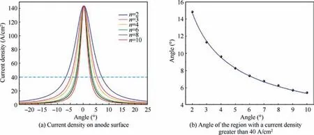
Fig.11 Current density distribution on anode surface for various angular velocity ratios.

Fig.12 Trajectories of cathode tool for different radii when angular velocity ratio n = 6.
Fig.8 shows the simulated profiles of convex structures when n=3,6,or 9.There are clearly differences.The accuracy indexes are plotted in Fig.9 for the different angular velocity ratios.Fig.9(a) shows the trends for D, H, RD, and RG.The width D of the convex structure increases with an increase of the angular velocity ratio.The height H decreases linearly with an increase of angular velocity ratio over a certain range.With an increase of the angular velocity ratio, the top fillet RDand root fillet RGfirst decrease and then remain unchanged.As shown in Fig.9(b), the inclination angle α of the sidewall decreases rapidly with an increase of the angular velocity ratio.
To explore why the angular velocity ratio affects the machining accuracy of a convex structure, the current density distribution in the electrolyte domain Ω is calculated with simulation software(COMSOL 6.0).As shown in Fig.10,there is a high current density region only in the narrow gap near the processing area.In addition, the current density on the anode surface in the processing area is calculated for various angular velocity ratios, as shown in Fig.11(a).The peak current density is the same for the different angular velocity ratios.Fig.11(b)shows the angle of the region where the current density is greater than 40 A/cm2for different angular velocity ratios.With an increase of the angular velocity ratio,the angle of the high current density region decreases sharply at first and then decreases slowly.The smaller the angle of the high current density region, the better the localization and the higher the machining accuracy of the convex structure.However, if the angular velocity ratio is too high, the cathode radius will be small, which may overly limit the width of the cathode window.
3.2.Determination of cathode tool radius
Here, the angular velocity ratio n = 6 is used to study the influence of the cathode tool radius on the formation of a convex structure.The other simulation parameters are listed in Table 1.Fig.12 shows close-ups of the trajectories of cathode tools with different radii.When RC= 16.5 mm, both sides of the convex structure have a conical profile.For RC=17 mm,the sidewalls of the convex structure are V-shaped.When RC-≥17.5 mm, the sidewalls are straight.The inclination angle α and the fillet RGof the convex structure both increase as the radius of the cathode tool increases.Regardless of the cathode radius,the trajectories of contour points A and B always have a non-zero inclination angle, which suggests that the inclination angle α of a convex structure cannot be zero.A small difference in the radius of the cathode tool changes the trajectories of contour points A and B, and so the contour of convex structure also changes.
The profile of the convex structure is simulated under electrochemical dissolution when the angular velocity ratio n = 6 and the cathode radius RC= 17.5 mm.Fig.13(a) shows the evolution of the convex structure on the inner surface of a revolving part at different machining times.The cathode tool is fed continuously toward the anode workpiece,and the material of the anode workpiece is rapidly removed under the high current density.The convex structure becomes narrower over time, and the fillet RDand the fillet RGgradually decrease.The inclination angle α of the sidewall becomes significantly smaller.The corrosion caused by stray current has a great impact on the machining accuracy of the convex structure.The error between the simulated profile under electrochemical dissolution and the trajectory envelope is large at the top of the convex structure, as shown in Fig.13(b).In Section 3.4, the causes of the error are discussed in detail.
3.3.Determination of cathode window width
The machining accuracy of the convex structure is also affected by the width D of the cathode window.The angular velocity ratio n = 6 and the cathode radius RC= 17.5 mm are used in the simulation.The other simulation parameters are listed in Table 1.Fig.14 shows the simulated profiles of convex structures with different values for the angle of the cathode window.As the angle θ increases, the angle β of the convex structure also increases.The angle θ of the cathode window and the central angle γ for the trajectories of the contour points satisfy the following:
To quantitatively analyze the profiles of the convex structures for different values of the angle of the cathode window,the accuracy indexes are plotted in Fig.15.It can be seen from Fig.15(a)that the fitting curves of the simulation results for H,RD, and RGare horizontal, which indicates that they do not change with an increase of the angle of the cathode window.Fig.15(b) shows that as the angle of the cathode window increases in a certain range, the inclination angle α and the angle β increase linearly.The angle θ of the cathode window and the angle β of the convex structure satisfy the following:

Fig.13 Simulated profiles of a convex structure.

Fig.14 Simulated profiles of convex structures with different values for angle of cathode window.

Therefore, the width of the cathode window can be calculated according to the desired width of the convex structure.
3.4.Formation of a convex structure under electrochemical dissolution
In ICRECM, the error between the simulated profile under electrochemical dissolution and the trajectory envelope is large at the top of the convex structure, as shown in Fig.13(b).To explore the causes of this error,the current density on the surface of the convex structure is researched during the 500th rotation.With an angular velocity of 6 r/min, it takes 8 s for the cathode tool to move from position Ⅰto position Ⅱ, as shown in Fig.16.In this paper, 304SS is used as the material of the anode workpiece.The minimum current density to break the passive film of 304SS is 3.96 A/cm2.34,35When the current density is lower than 3.96 A/cm2, the material will not dissolve.

Fig.15 Accuracy indexes of a convex structure for different values of the angle of the cathode window.
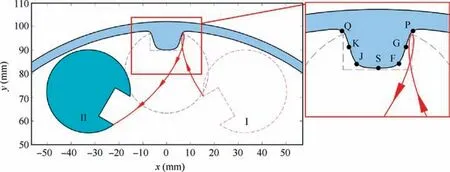
Fig.16 Cathode movement during the 500th rotation.

Fig.17 Current density distribution on surface of convex structure at different machining times.
Fig.17 shows the current density distribution on the surface of the convex structure at different times.The motion can be divided into two stages according to the position of the cathode tool relative to the convex structure.In the first stage,from 0 to 4 s, the cathode rotates close to the convex structure, as shown in Fig.17(a)–(d).The stray current sweeps through points F, G, and P in turn.The current density gradually increases during this time.In the second stage, from 4 to 8 s,the cathode rotates away from the convex structure, as shown in Fig.17(d)–(g).The right profile of the convex structure is attacked again by the stray current in this time.Similarly,the left profile of the convex structure is also attacked twice by the stray current.In summary, the convex structure is attacked twice by the stray current during each rotation.
The current densities of characteristic points at different times are shown in Fig.18.The figure gives the start and end times of material dissolution for each point.The current density curves for symmetrically positioned characteristic points are symmetrical,which means that the convex structure fabricated is also symmetrical.
There are two peaks in the current density curve of point S in time 0–8 s, as shown in Fig.18(a).However, the peak current density is lower than 3.96 A/cm2, so the material near point S does not dissolve.In Fig.18(b) and (c) there are also two peaks in the current density curves, and the peak current density exceeds 3.96 A/cm2.The material near points F, J,G, and K is dissolved twice in time 0–8 s.The material near points F and J dissolves to form the fillet RDat the top of the convex structure.As shown in Fig.18(d), the current density curves of points P and Q have only one peak,and the peak current densities are as high as 72 A/cm2.The period when the current density exceeds 3.96 A/cm2lasts for 1.73 s.In Fig.17(c) and(e), the high current density regions are at the roots of the convex structure and include points P and Q.A large amount of material in these regions is removed so that the height of the convex structure increases.
In summary,the sidewall of the convex structure is attacked by stray current many times during each rotation, resulting in the excess dissolution of the material.In the fabrication of a convex structure, the duration of when the stray current attacks the sidewall increases from the top to the root, which leads to the error in the profile shown in Fig.13(b).Therefore,the error between the simulated profile under electrochemical dissolution and the trajectory envelope is inevitable.
4.Experimental validation
4.1.Experimental procedure
As shown in Fig.19, a self-designed experimental set-up was used to study the formation of convex structures on the inner surface of a revolving part.The electrolyte distributor was used to redistribute the electrolyte, so that the pressure and flow in the jet nozzle were stable.The high-speed electrolyte was sprayed from the jet nozzle and flushed through the narrow electrode gap from the side.The anode workpiece and cathode tool were, respectively, mounted on two rotating shafts, which rotated in the same direction.The cathode tool was simultaneously fed along the line of centres.

Fig.19 Experimental set-up for ICRECM.
Workpieces of stainless steel 304 with an inner surface radius of 90 mm were used in the experiment.Two cylindrical cathode tools were used to machine the anode workpieces with ICRECM.One had a radius of 17.5 and the other 31 mm.The angular velocity ratios were 6 and 3,respectively.For the cathode tool with a radius of 17.5 mm, as shown in Fig.20(a)and(b), two rectangular windows of widths 12 and 18 mm were fabricated in it.The windows were insulated by ceramic.The other tool had a single insulated window of width 18 mm, as shown in Fig.20(c).The applied voltage was 25 V, and the electrolyte was 20wt% NaNO3, which was kept at a constant temperature of 30 °C during the experiment.The feed depth of the cathode tool was 8 mm at a constant speed of 0.012 mm/min.

Fig.20 Photographs of cathode tools.
4.2.Experimental results
As shown in Fig.21, multiple convex structures were successfully fabricated on the inner surface of thin-walled revolving parts using cathode tools of different radii.Fig.21(a) shows that the cathode with a single insulated window makes three convex structures on the inner surface of the anode workpiece when the angular velocity ratio was 3.In contrast, Fig.21(b)shows that with the other tool with two windows, when the angular velocity ratio was 6,12 convex structures with two different widths were fabricated on the anode workpiece.
The coordinates of different points on the profiles of the convex structures were measured.The accuracy indexes of the convex structure were obtained by fitting these points with Matrix Laboratory (MATLAB 2020).

Fig.21 Pictures of workpieces machined using ICRECM.

Fig.22 Photographs showing the profiles of fabricated convex structures.

Table 2 Accuracy indexes for the fabricated convex structures.

Fig.23 Comparison of simulated and experimental convex profiles (top) and errors (bottom).

Fig.24 Errors between simulated and experimental results for accuracy indexes.
Fig.22 shows the profiles of the convex structures fabricated with different experimental parameters.The values of the accuracy indexes for the fabricated convex structures are presented in Table 2.The fillet radii RDand RGand the height H of the convex structures I and II are approximately equal,but the inclination angle α is larger for DC=18 mm.In addition, the widths of the convex structures are 7.95 and 13.82 mm, respectively, which are consistent with Eq.(27).Comparing structures Ⅱand III, the height H, the fillet radii RDand RG, and the inclination angle α are larger for n = 3.In conclusion,the trends for the accuracy indexes of the fabricated convex structures are consistent with the simulation results.
Fig.23 shows that the simulated and experimental convex profiles are in good agreement and that the errors are within the permissible range.The profiles of the convex structures are symmetrical, so the errors between the simulated and experimental results are also approximately symmetric.Fig.24 shows the errors between the simulated and experimental results for accuracy indexes over the three types of convex structure.The errors for the height H and the width D are small, whereas the errors are larger for the fillet radii.However,the errors between the simulated and experimental results are within the allowable error range for the process,so that the machining performance is acceptable for industrial applications.
5.Conclusions
In this paper,mathematical equations are derived for the complex relative motion of the electrodes and the material removal model is established based on the kinematic equations for the electrodes and Faraday’s law.Multiple convex structures are fabricated on the inner surface of a revolving part using ICRECM.The main conclusions can be summarized as follows:
(1) The material removal process is simulated numerically,and the evolution of anode profile is investigated.Over time, the amount of material dissolved in each time interval increases.
(2) The simulation results indicate that the machining accuracy of the convex structure strongly depends on the angular velocity ratio, the radius of the cathode tool and the width of the cathode window.As the angular velocity ratio n increases, the inclination angle α decreases significantly.When n ≥10, the inclination angle α is less than 9°.When RC≥17.5 mm, the sidewalls of the convex structure are straight.As the angle θ of the cathode window increases, the angle β of the convex structure also increases.
(3) The sidewall of the convex structure is attacked by stray current many times during each rotation,resulting in the excess dissolution of the material.The excess dissolution of material during electrolysis causes errors between the simulated profile and the trajectory envelope of the cathode tool.
(4) Multiple convex structures were simultaneously fabricated on the inner surface of a thin-walled revolving part,indicating that ICRECM has good machining performance.The error between simulated and experimental results for accuracy indexes is less than 7%, which verifies that the proposed simulation model is valid for predicting convex shapes fabricated using ICRECM.
Declaration of Competing Interest
The authors declare that they have no known competing financial interests or personal relationships that could have appeared to influence the work reported in this paper.
Acknowledgements
This work is supported by the National Natural Science Foundation of China (No.52175414), National Natural Science Foundation of China for Creative Research Groups(No.51921003), the China Postdoctoral Science Foundation(No.2019M661833).
杂志排行

CHINESE JOURNAL OF AERONAUTICS的其它文章
- Improving surface integrity when drilling CFRPs and Ti-6Al-4V using sustainable lubricated liquid carbon dioxide
- A hybrid chemical modification strategy for monocrystalline silicon micro-grinding:Experimental investigation and synergistic mechanism
- Analysis of grinding mechanics and improved grinding force model based on randomized grain geometric characteristics
- Experimental and modeling study of surface topography generation considering tool-workpiece vibration in high-precision turning
- Collaborative force and shape control for large composite fuselage panels assembly
- Ultrasonic constitutive model and its application in ultrasonic vibration-assisted milling Ti3Al intermetallics