Metal flow hysteresis behavior and shape control strategy during porthole die extrusion of micro heat pipe
2023-09-05YongdaLIUJieXUXiaoliangWANGDebinSHANBinGUO
Yongda LIU, Jie XU, Xiaoliang WANG, Debin SHAN, Bin GUO
Key Laboratory of Micro-Systems and Micro-Structures Manufacturing of Ministry of Education, Harbin Institute of Technology, Harbin 150080, China
School of Materials Science and Engineering, Harbin Institute of Technology, Harbin 150001, China
KEYWORDS Micro heat pipe;Microforming;Size effect;Porthole die extrusion;Metal flow;Forming integrity;Microstructure
Abstract The shape control strategy of micro grooves is still unclear and challenging during the porthole die extrusion of grooved micro heat pipe(MHP).Through the simulation and experiment of porthole die extrusion of a MHP profile,the metal flow hysteresis behavior within micro features and the effect of ram speed and extrusion temperature on it and the resulting forming integrity was elucidated.Innovatively,Taguchi design and variance analysis(ANOVA)were introduced to determine their influence magnitude on the metal flow uniformity calculated by simulation results.The main findings are given below.The metal flow hysteresis derives from part feature size effect.The negligible friction-affected area during conventional extrusion severely slows down the metal flow within micro features during the MHP profile extrusion, which is due to the surge in the area ratio of the friction-affected area to the region in which it is located.Neither ram speed nor extrusion temperature can change the distribution of the friction-affected area.However, increasing ram speed multiplies the metal flow hysteresis and severely reduces the forming integrity,whereas extrusion temperature has little effect.Following this strategy,batch extrusion of the profile with microgrooved width of 0.27 ± 0.02 mm was achieved in industrialized conditions.
1.Introduction
Heat pipes are heat transfer passive devices that operate on the principle of vapor–liquid phase change and are suitable for aerospace applications and heat dissipation in electronics due to their advantages of high heat transfer performance and compactness.1The capillary wick structure of heat pipes provides the driving force for the liquid in the condenser to flow back to the evaporator, which is crucial for the proper operation of heat pipes.A wick consists mainly of sintered,grooved, and composite types, according to their structural characteristics.2In aerospace, axially grooved heat pipes(AGHPs) made of aluminum alloy and filled with ammonia as working fluid are favored in satellites and their thermal control systems,3,4which is due to their uniform temperature,excellent reliability, process consistency and lightweight.The structure of the AGHPs can be found from this literature of Hoa et al.3, and their operational temperature range of-40 °C to + 80 °C is well suitable for space applications.For example, back in 2003, Baturkin et al.5reported that U-shaped AGHPs have been applied to the elaboration and flight exploitation of thermal control systems for the microsatellites Magion 4, Magion 5 and BIRD.Shao et al.6disclosed that AGHPs helped achieve thermal coupling between the panels on the Chang’e-1 satellite, which solved the problem of high temperatures in the batteries.Regarding the lifetime of AGHPs, Barantsevich and Shabalkin7reported that AGHPs can serve for more than 15 years in the application of cable thermal control for the solar battery drives integrated into the International Space Station.However, with recent advances in space technology towards miniaturization and integration,8thermal control of spacecraft is more challenging than ever.In response to this situation,axially grooved micro heat pipes (MHPs) provide a miniaturized and lightweight thermal management solution.MHPs with crosssectional dimensions of a few millimeters show promising applications in microsatellites and microthermal control systems in aerospace.Baturkin9noted that micro heat pipes with an external circular diameter of 1–6 mm are critical for miniaturized designs of microsatellites.This type of heat pipe indeed exhibits attractive advantages, such as solving the watt-level heat dissipation issues for sensitive components of the charge coupled device (CCD) camera in narrow space in a satellite thermal control system.10
However,fabrication techniques for MHPs of this type suffer from many problems, and one of the pressing issues is the shape control of the micro grooves during extrusion.The micro grooves of heat pipes are typically less than 1 mm in width and height, resulting in their fabrication falling into the category of microforming.Smaller groove widths of heat pipes represent higher capillary heat transfer limits,11but this also brings great troubles to its hot extrusion, such as the difficulty of fully extruding micro grooves.12According to prior studies,13,14hot extrusion of MHPs has proved to be unique and compelling.For example, complex micro groove and ultra-large extrusion ratio(i.e.,the ratio of cross-sectional area of containers to extrudates) of MHPs can cause many problems,such as extremely poor forming integrity owing to highly uneven metal flow13and severe surface back-end defects caused by rare forward flow behavior of billet skins.14Taking the forming quality of MHPs,which this present paper focuses on, as an example, Liu et al.13reported that in the hot extrusion of an Al MHP profile at an ultra-large extrusion ratio of 205,the micro grooves failed to extrude even at a very small ram speed of 1.4 mm/s,and the primary reason was attributed to the uneven metal flow within the die bearing caused by size effect.Evidently, an in-depth understanding of the metal flow behavior subjected to size effect during hot extrusion is crucial to ensure the forming quality of MHPs.However, to the best of our knowledge, little research has been reported on the hot extrusion technology of complex micro-grooved hollow profiles such as MHPs, and most studies of the size effectaffected metal flow behavior during extrusion and microextrusion used cold extrusion process.To date, the metal flow behavior during cold micro-extrusion,as well as some cases of extrusion process realizations of complex micro parts (mainly solid micro gears), has been widely investigated.
Compared to conventional extrusion, grain size and workpiece size can cause uneven metal flow during micro-extrusion,which is generally detrimental to the forming quality of extrudates.Parasiz et al.15reported that as the grain size (211 μm)approached the workpiece size (568 μm), the deformation characteristics of the extruded micro pins made of CuZn30 α-brass were dominated by the size and location of specific grains, resulting in an uneven distribution of plastic strain and hardness, which caused the curving tendency.On this basis, Parasiz et al.16illustrated that during micro-extrusion,the penetration of shear deformation occurred for the coarse-grained material, and the imposed strain gradients became steeper with the decrease of workpiece size.Similarly,based on the micro-extrusion of pure coper with various grain sizes,Chan et al.17found that the inhomogeneous deformation occurred in the case with coarse grains, which showed extensive slip bands across the grain boundaries for strain continuity.Interestingly, the size effect is not entirely negative for micro-extrusion process.Experimental results by Ghassemali et al.18revealed that the dead metal zone in the extruded micro pins could be removed by increasing the initial grain size of the workpiece,which was attributed to the effect of the strain gradient on the deformation.Recently, further research on the interactive effect of grain size and crystal structure on the deformation behavior during the progressive microforming process including piercing, two step extrusion, and blanking was investigated by Tang et al.19They revealed that for facecentered cubic (FCC) Cu and body-centered cubic (BCC) Fe,the length of extrudates of the micropart was reduced with the increase of initial grain size owing to the enhanced lateral metal flow in the coarse-grained material, while the dependency of its length on the initial grain size for hexagonal close-packed(HCP)Ti became unnoticeable owing to the subdivision of the original grains by the generated deformation twins.
Regarding the micro-extrusion process of complex micro parts, micro gears for micro-electro-mechanical systems(MEMS) parts are most usually studied.During the microextrusion of micro gears, the metal flow within micro features(e.g., the teeth of micro-gears) is idiosyncratic compared to other areas, which is similar to the hot extrusion process of MHPs.13Nanthakumar and Rajenthirakumar20recently reported that the hardness of the tooth region of the coldextruded micro gear made of cooper was higher than that of the central region.They believed that the most serious deformation occurred in the tooth region, resulting in the smallest grain size owing to low grain growth rate at room temperature.In the hot micro-extrusion of 7075 aluminum alloy micro gear,Dong et al.21indeed observed that the grain size at the tooth region was smaller than that at the central region, whereas the micro hardness of the tooth region was smaller.Based on the microstructure of the micro gears, it was attributed to the smaller amount of rigid second phase particles at the tooth region.In terms of improving the differences in microstructure distribution between the tooth and central regions of micro gears, Khalilpourazary22determined that fine-grained initial billets prepared by ECAP process were able to reduce the inhomogeneity of the microstructure within micro gears.
In summary, despite numerous excellent reports on the metal flow behavior subjected to size effect in the microextrusion of micro parts,the reason for the uneven metal flow within micro features is still ambiguous and has not received much attention.More importantly, the influence of extrusion process parameters on the uneven flow behavior is still unclear,which is very important for the formulation of extrusion parameters and seriously restricts the realization of industrial production of micro extrudates and macro extrudates with micro features (e.g., MHPs).
Following these above studies, the aim of this paper was established to present comprehensive simulated and experimental investigations of the formation mechanism of the uneven metal flow behavior within micro features during hot extrusion of MHPs and the influence magnitude of extrusion process parameters on it and the resulting forming integrity.In this study, the hot extrusion of an aluminum alloy MHP with 0.27 mm wide micro grooves was studied,and its porthole die with unequal length of bearings was designed for use in an industrial extruder.The metal flow behavior at the profile exit of the die during hot extrusion was obtained by HyperXtrude software, and the metal flow uniformity was calculated from the simulated results.Following this, Taguchi design and ANOVA were innovatively introduced to determine the influence magnitude of ram speed and extrusion temperature on the metal flow uniformity.To validate the simulation results, the experimental results including the head profile shape, forming integrity and microstructure of the MHP profile were analyzed.This study provides a crucial basis for the design of extrusion dies and the formulation of extrusion parameters for MHP-like extruded products in practical production using industrial extruders.
2.Material and method
2.1.Material and porthole die design
The as-cast 6063 aluminum alloy was used as the material for the MHP profile, and its chemical composition is given in Table 1.It is most commonly used in the manufacture of MHPs due to good comprehensive properties such as mechanical, welding properties and corrosion resistance.(ED) was depicted to understand the extrusion process.Depending on the structural characteristics of the profile, the design idea was proposed with a relatively small extrusion ratio, short bearing, low weld chamber and local structural strengthening.The specific reasons were listed as follows:(1)Four die orifices were set,which sharply reduced the extrusion ratio from 548 to 137; (2) the overall bearing length was set to 3 mm.The bearing length in aluminum alloy extrusion is generally 2 to 8 mm.Longer bearing can aggravate the uneven metal flow at the profile exit of extrusion dies,whereas shorter bearing can cause periodic cracks on extruded products; (3) to prevent unacceptable deflection deformation of the die core, not only a small weld chamber height of 8 mm,but also a local strengthening structure(shown in Detail A)was designed.In summary,the main die parameters are the extrusion ratio of 137,die core spacing of 28 mm, weld chamber depth of 8 mm, overall bearing length of 3 mm and porthole outer radius of 30 mm.
Further detailed design of the bearing length was performed to optimize the die structure in Fig.3.This is because numerous studies confirmed that bearing length design could balance the metal flow at the profile exit of extrusion dies.23–27Decreasing the local bearing length results in an increase in the local metal flow velocity, otherwise the opposite.23Generally,designer can slow the metal flow in thick sections of extrudates by increasing the bearing length.24Liu et al.25reported that using an unequal bearing length, the difference of the profile exit velocity (PEV) was decreased from 7.71 to 2.00 mm/s.Therefore, the unequal length of bearing(Scheme 2) was designed to perform the simulated and experimental studies.Considering that a short bearing increases the metal flow velocity at the profile exit, and that, to the best of the author’s knowledge, the bearing length of an aluminum alloy extrusion die is typically not less than 2 mm, otherwise the extrudates may be prone to periodic cracks or other defects.Therefore,a local bearing length of 2 mm in Scheme 2 is set for the micro rib area with difficult metal flow.
2.2.Steady-state extrusion simulation
To obtain the velocity and strain distribution at the profile exit of the die,the steady-state extrusion process of the profile was simulated using HyperXtrude based on Arbitrary Lagrange Eulerian (ALE) algorithm under the following extrusion process parameters: billet temperature of 480 °C, die temperature of 460 °C, container temperature of 420 °C, and ram speed of 0.7 mm/s.Both bearing design Schemes in Fig.3 were simulated to incidentally determine the effect of the optimal design of the bearing.
The preprocessing procedure is that after meshing,entering material properties and applying boundary conditions, the solutions were performed with a nonlinear iteration tolerance of 0.001.Specifically, the billet diameter and length were designed to be ∅85 and 200 mm, respectively.The metal flow domain in the container and porthole die was geometrically modeled and discretized by meshing to simulate the steady-
Fig.1 shows the geometric model and key dimensions of the MHP profile.Obviously, the ultra-large extrusion ratio,complex micro groove and small inner radius are the most prominent characteristics that need to be focused on when designing the porthole extrusion die.A schematic diagram of the extrusion process using a porthole die can be found in the literature by Liu et al.13.
A porthole die was designed to extrude the MHP profile on an industrial horizontal extruder, and one billet can generally extrude tens of meters of the profile.The overall design of the porthole die is shown in Fig.2, and the extrusion directionstate extrusion process, as shown in Fig.4.The bearing and profile are triangular prism elements, and the others are tetrahedral elements.Notably, the mesh of the micro rib must be locally refined to ensure the simulated accuracy.As shown in the enlarged Detail B view in Fig.4, at least three mesh elements are divided on each edge.For the finite element (FE)model, the minimum element size of the profile, bearing and weld chamber is 0.08 mm, and that of the porthole and billet is 0.5 and 1.5 mm, respectively.The maximum element size of 7 mm comes from the billet.With regard to the simulation parameters and boundary conditions,refer to the study by Liu et al.14.

Table 1 Chemical composition of 6063 aluminum alloy.

Fig.1 Key dimensions and geometric model of MHP profile.

Fig.2 3D model of the overall design of porthole die.

Fig.3 Bearing design of the porthole die.

Fig.4 FE model of metal flow domain in hot extrusion of MHP profile.
Exploratively, this study attempted to simulate using the conventional material constitutive model rather than that obtained from microforming tests (e.g., micro-compression),and discussed the reliability in combination with the experimental results.The specific reasons for this choice are as follows: On the one hand, Chan et al.28found that, using the calibrated flow stress–strain curves obtained from microcompression, the simulated results in a cold micro-double cup extrusion of 6061 aluminum alloy were in good agreement with their experimental results.However,the flow stress–strain curve obtained from micro-compression is clearly not suitable for the extrusion simulation of MHP profiles because it contains not only micro features but also macro features.On the other hand, due to the complex microstructure evolution during porthole die extrusion of MHP profiles,the size effect during the hot extrusion of micro grooves of MHP profiles may be different from that in the case of cold micro-extrusion.
2.3.Taguchi design for extrusion process parameters
Combined with the simulated results, Taguchi design and ANOVA were used to analyzed the influence magnitude of ram speed and extrusion temperature on the metal flow uniformity during hot extrusion of the profile.Taguchi design typically requires only a portion of a full factorial experiment,but it ensures balanced comparisons of levels of any one factor.Through analyzing the results of signal-to-noise ratio (referred to as S/N for short) and ANOVA in Taguchi design,Wang et al.29successfully determined the contribution rate and optimal parameter combination of five control factors to the measurement of thermal drift.Regarding the application of Taguchi design in extrusion process,Hsia30combined Taguchi design and FE simulation to determine the better conditions in the micro-extrusion of micro pins, and proved the application potential of this method in microforming process.
In this study,the investigated extrusion process parameters,including billet,die and container temperatures and ram speed,were selected as the control factors shown in Table 2, and a L16(44) Taguchi design with four factors and four levels was adopted.
The standard deviation of velocity (SDV) for the PEV was employed to characterize the metal flow uniformity.To reduce unnecessary calculations,the SDV value was calculated by 1/8 of the profile cross section (i.e., the area of interest (AOI) in Fig.1), which was divided into 20 regions.The mathematical expression of SDV is
where νmis the PEV of the center nodal at the selected region m (mm/s), ν- is the average PEV of all the divided regions (mm/s), and M is the number of the divided regions.Large SDV value represents more uneven metal flow.The SDV values for the 16 sets of extrusion parameters in Table 3 were calculated from the results of 16 steady-state extrusion simulations.
In Taguchi design,the S/N mainly includes three characteristics, namely larger-is-better, smaller-is-better, and nominalis-best.The SDV value is expected to be minimized, thus the S/N of the smaller-is-better characteristic was selected for the SDV value.For K experimental repetitions with a given sample, the S/N of SDV value is computed according to the following Equation:
where k is the sequence number of repeated trails, K is the number of repeated trials, and K =1 here.The unit of S/N is dB.The larger the S/N value,the smaller the SDV value,which means more uniform metal flow during extrusion.
Based on the data of the S/N in Taguchi design, mean values of the S/N for each level and ANOVA for each factor were calculated, and the calculation procedure is detailed in the Appendix A.

Table 2 Summary of the selected control factors and their levels.

Table 3 L16(44)Taguchi design with corresponding values of SDV and S/N.
2.4.Profile extrusion and characterization
The hot extrusion experiments were performed on a 6.3 MN horizontal industrial extruder (XJ-690UST, Yuanchang Co.,China) with a container diameter of ∅90 mm.Before extrusion, the billets were homogenized through holding for 18 hours at 530°C.According to Scheme 2 in Fig.3,the porthole die in Fig.5 was manufactured by the computer numerical control (CNC) machine and electron discharge machine(EDM)method.As depicted in Fig.5,the profile was extruded out of the die as the ram loads along the ED.The profile was cooled by online forced air cooling without straightening and heat treatment.Herein, the billet temperatures of 420 °C,450 °C and 480 °C were selected with other extrusion parameters of die temperature of 460 °C, container temperature of 420 °C and ram speed of 0.7 mm/s.The reasons for only verifying the billet temperature are as follows.Regarding ram speed, Liu et al.13validated that increasing ram speed aggravated the uneven metal flow and degraded the forming integrity of micro grooves during hot extrusion of a MHP profile.In terms of extrusion temperature,the simulated results in this study showed that the effects of billet, die and container temperatures on the metal flow behavior at the profile exit were similar.
After extrusion, the head profile shape, dimension accuracy,surface micromorphology and microstructure of the profile were characterized to verify the simulated results.Through macroscopic observation of the head profile shape, the metal flow at different positions of the head profile was analyzed when the profile was just extruded out of the die.Subsequently, the forming integrity and dimension accuracy of the profile were measured by a video measuring system (VMS-2515F,Wanhao Co.,China).After that,the surface micromorphology of the micro rib was obtained using a scanning electron microscope (SEM) (Quanta 200FEG, FEI Co., USA).Finally, the electron backscatter diffraction (EBSD) analysis of the cross-section of the homogenized billet and the metallographic observation of the profile extruded at the billet temperature of 480 °C were performed, and the preparation of the electropolished EBSD samples was consistent with the study by Liu et al.13.The metallographic observations were concentrated near the area of interest in Fig.1.Before observations,the polished samples were anodized by electrolytic etching at 20 V in a mixed solution consisting of 5 mL HBF4and 200 mL deionized water.Subsequently, a polarized optical microscope(Axio Imager A2m,Zeiss Co.,Germany)was used to obtain the metallographic images.Notably, the reason for the microstructure characterization is that severe uneven metal flow behavior generally affects the microstructure,so it can not only indirectly verify the simulations, but also serve as a preexploration for the microstructure evolution studies during hot extrusion of the MHP profile.
3.Results
3.1.Metal flow hysteresis behavior
The velocity distribution in Fig.6 shows that the uneven metal flow and high PEV at the profile exit are the two main characteristics during the hot extrusion.We refer to the uneven metal flow phenomenon as metal flow hysteresis behavior, which results from the complex micro-grooved features of the profile.Taking Scheme 1 in Fig.6(a) as an example, the metal flow hysteresis behavior can be categorized into two aspects.On the one hand, the metal flow velocity within the micro rib was considerably lower than that in the base region.On the other hand, significant differences were found in the PEV within the micro rib.Specifically, combining Fig.1 and Fig.6 (a), a large velocity gradient from Area 18 to Area 20 was observed in the area of interest.The closer to the top of the micro rib,the smaller the PEV.As for the high PEV caused by ultra-large extrusion ratio shown in Fig.6, the maximum PEV during extrusion was as high as 154 mm/s, whereas the ram speed was only 0.7 mm/s.An ultra-large extrusion ratio means that the cross-sectional area of the die orifice is much smaller when the billet diameter is constant.However,the volume of the metal flowing out of the die per unit time at a certain ram speed is constant.Thus, the PEV is much greater at an ultra-large extrusion ratio.

Fig.5 6.3 MN industrial extruder and porthole die.

Fig.6 Metal flow behavior at the profile exit during hot extrusion of the profile extruded by different dies.
To deeply understand the metal flow hysteresis behavior,the strain distribution was analyzed.Overall, as can be seen from Fig.6(a), the strain at the thick-walled area (e.g., Point P2)where the metal with a faster flow velocity was easy to flow was the smallest,whereas the strain at the micro rib area(e.g.,Point P1) where the metal with a slower flow velocity was difficult to flow was the largest.The high strain area in Fig.6 indicates that the most severe plastic deformation occurs at the top of the micro rib.It can be determined that the material within the micro ribs undergoes more serious plastic deformation during hot extrusion.Unlike the PEV, the strain distribution at the profile exit was not only related to the shape and wall thickness of the profile,but also to the position at the profile exit.Under the same wall thickness and shape, the strain at the upper left corner of the profile was higher than that at the lower right corner of its axis symmetry owing to the asymmetry of the metal flow in the weld chamber.
Incidentally, the effect of the optimal bearing design was also investigated.Fig.6 shows that after locally decreasing the bearing length for the micro rib in Scheme 2, the area of low PEV and high strain within the micro rib declined greatly.These results demonstrated that the bearing design of unequal length for micro features can indeed balance the metal flow at the profile exit.
3.2.Taguchi design result and ANOVA
The L16(44) Taguchi design and corresponding calculation results are presented in Table 3.
To intuitively determine the optimal combination of the extrusion process parameters, the mean S/N curves were plotted in Fig.7 for various factors and levels.It was evidently that the optimal parameter combination was A4B3C3D1.Fig.7 indicates that the smaller the ram speed, the greater the S/N value, implying more uniform metal flow at the profile exit during hot extrusion of the MHP profile.Interestingly, unlike ram speed,extrusion temperature had little effect on the metal flow uniformity during extrusion.
Based on the ANOVA results for the S/N in Table 4, the significance and contribution rate of each factor to the metal flow uniformity at the profile exit were further determined to quantify the influence magnitude of each extrusion process parameter.Regarding ANOVA, a P value less than 0.01 indicates that the association between factor and test index(i.e., S/N) is highly significant, and a P value greater than 0.1 is insignificant.Table 4 shows that the P value of ram speed was less than 0.005,thus the impact of ram speed on the metal flow uniformity during hot extrusion is extremely significant.However, the P values of extrusion temperature (e.g., billet temperature) are greater than 0.10, which confirms their insignificant correlation to the metal flow uniformity during hot extrusion.

Fig.7 The average S/N for four factors at various levels.
The contribution rate ηiof each factor can be determined by
where i is the sequence number of the ith factor in Table 2,niis the number of factors, and Fiis Fisher’s value of the ith factor.During hot extrusion process of the profile, the effect of ram speed on the metal flow uniformity at the profile exit is dominant with a contribution of as high as 99.64 %.However, the influences of extrusion temperature are almost negligible,because the contribution rates of billet,die and container temperatures are only 0.17 %, 0.11 % and 0.09 %, respectively.In other words, extrusion temperature does not need to be taken into account when optimizing the metal flow uniformity at the profile exit during hot extrusion of MHPs.
3.3.Head profile shape
The metal flow hysteresis behavior found in the simulation was confirmed through macroscopic observation of the head profile.Fig.8(a) indicates that the metal flow within the micro rib lagged far behind that within the base region, which verified the simulated results in Fig.6.In other words, the PEV within the micro rib region is considerably smaller than that within the base region.Additionally, consistent with the simulated results, there are also significant differences in the metal flow within the micro rib.For example, the metal flow at the top of the micro rib lagged seriously behind that at the bottom.Furthermore, the shape of the head profile extruded ranging from 420 to 480°C in Fig.8 was used to evaluate the influence of billet temperature on the metal flow hysteresis behavior.Through macroscopic observation, no significant difference in the shape of the head profiles extruded at various billet temperatures can be identified.Therefore,the experimental results also show that the billet temperature has no significant effect on the metal flow uniformity during hot extrusion of the profile.
3.4.Dimension accuracy
The forming integrity and dimension accuracy of the profile were further investigated.Fig.9 shows that the forming integ-rity of the micro grooves was very good at various billet temperatures, and both the complex micro-grooved feature and the outer fillet of the profile were completely extruded.However,the No.6 micro groove(highlighted by green dashed line)extruded at the billet temperature of 420°C was slightly wider.
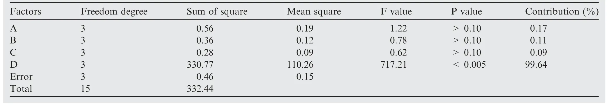
Table 4 ANOVA results for S/N.

Fig.8 Macroscopic observation of the head profiles extruded at various billet temperatures.

Fig.9 Cross-sectional images of the profiles extruded at various billet temperatures.

Fig.10 Dimensions of micro grooves of the profile extruded at various billet temperatures.
To determine the influence of billet temperature on the dimension accuracy of the profile, the minimum width dimension (i.e., 0.27 mm) of all micro grooves was measured and counted in Fig.10.Under the condition of the billet temperatures of 480 °C and 450 °C, the dimension accuracy of all micro grooves was as high as ± 0.02 mm.Yet, the dimension of the micro groove No.6 extruded at the billet temperature of 420 °C was 0.295 mm in width, and its dimension accuracy decreased slightly.Nevertheless, the dimension accuracy of the micro-grooved width was still better than ± 0.03 mm,which was a good indicator.The slight decline in dimension accuracy of the profile extruded at the billet temperature of 420°C may be due to an increase in uneven metal flow caused by part feature size effect, but also a decrease in metal flow performance.
3.5.Surface micromorphology
The SEM images in Fig.11 show the top surface of the micro ribs on both sides of the micro groove No.5 of the profile.
The low-magnification images show that, consistent with the results in Fig.10, the profiles extruded at various billet temperatures had good consistency in the minimum width of the micro grooves.Under all billet temperature conditions,the surface quality of the micro ribs was highly excellent,showing the characteristics of extrusion streaks parallel to the ED.It is generally believed that in the hot extrusion of aluminum alloys without lubrication, extrusion streaks form due to a metal film adhering to the bearing that has a brushing effect on the surface of the extrudates flowing out of the extrusion die.No micro-cracks were observed, as indicated by the high-magnification images of the edges of the micro ribs near the micro groove No.6.Incidentally, the number and size of the extrusion streaks at the edge of the micro ribs were larger at the higher billet temperature of 480°C.However,it was not statistically significant due to the small observation area.

Fig.11 SEM images of the profiles extruded at various billet temperatures.
3.6.Microstructure
Fig.12 shows the microstructure of the homogenized as-cast billet and extruded profile.According to the literature by Sla´-mova´ et al.31, the metallographic image obtained by anodic coating method can not only show the grain morphology,but also reflect the grain orientation to a certain extent.This is due to the formation of Al2O3film on the sample surface.During the anodic coating of polycrystalline materials, the thickness of the films deposited on grains with different orientations is different.Consequently,they will show different contrast when observed under a polarizing microscope, and the color difference between grains represents the difference of crystal orientation.
As expected,the metal flow hysteresis behavior had a significant impact on the microstructure within the micro rib.Specifically, under the polarizing microscope, the grain color within the micro rib (e.g., Region 1) was completely different from that within the base region (e.g., Region 2), which indicated that the crystal orientations of the grains were distinct within these two regions.Region 1 consisted mainly of the grains of Orientation a, whereas Region 2 consisted of the grains of Orientation b.Interestingly, the difference in grain size between Region 1 and Region 2 was insignificant.
4.Discussion
4.1.Simulation credibility analysis
In this study, the conventional material constitutive obtained by the non-microforming tests was used to simulate the hot extrusion of the MHP profile.Therefore, necessary simulation credibility analysis was performed.Consistent with the study by Liu et al.13, the metal flow hysteresis behavior during hot extrusion of the MHP profile was found in the simulated results in Fig.6 and well verified by the experimental results in Fig.8.In addition, Fig.12(b) shows that the grain orientation within the micro rib was completely different from that within the base region.However, according to Fig.12(a), the as-cast billet had no obvious preferred crystal orientation,which indirectly proved the existence of the metal flow hysteresis behavior.Therefore, it can be determined that the steadystate extrusion simulation using the conventional material constitutive model is reliable in qualitatively predicting the metal flow behavior during hot extrusion of macro parts with micro features such as grooved MHP profiles.As for the reason, it may be due to the process characteristics of hot extrusion of MHP profiles.Specifically, in microforming, the critical number of grains along a certain direction that falls into the size effect occurrence range depends on the type of materials, such as ‘‘less than 10 grains”mentioned by Hansen32and Kim et al.33.However, unlike cold micro-extrusion, although the grain size of as-cast billets generally used in hot extrusion is large(e.g.,100 μm in this study shown in Fig.12(a)),it may be refined due to dynamic recrystallization when the material reaches the bearing after hot extrusion deformation.For example, Fig.12(b) shows that the number of grains in the width direction of the micro rib can even be up to 10 at most,which indicates that sufficient dynamic recrystallization occurred.It is evident from the reverse inference that considering the grain growth during hot extrusion process,the number of grains in the width direction of the micro rib is likely to be more when the material is about to flow into the bearing.To sum up, this is the reason why the conventional material constitutive model works well in the hot extrusion of micro grooves of the MHP profile.

Fig.12 Microstructure of billet and extruded profile.
4.2.Formation mechanism of the metal flow hysteresis behavior
The formation mechanism of the metal flow hysteresis behavior resulting from size effect during hot extrusion of the MHP profile is discussed based on the simulated results.According to Chan et al.17,the size effect on material deformation behaviors is manifested as grain size,workpiece size,part feature size and interfacial condition.To be precise,in the extrusion of the MHP profile,only the deformation of the micro rib belongs to micro-extrusion,and that of the other parts belong to conventional extrusion.Thus, this metal flow hysteresis behavior is due to the part feature size effect.
In this study, the friction-affected area was proposed to elaborate the metal flow hysteresis behavior caused by part feature size effect.As shown in Fig.6, the presence of the friction-affected area can be inferred from the velocity distribution near the surface in contact with the die.Specifically,it is subjected to the frictional resistance reverse to the ED when the metal contacting the die (e.g., die core and orifice)is extruded out of the die.Taking Point P3 in Fig.6 as an example, the frictional resistance can reduce the metal flow velocity and increase the deformation intensity of the layer of metal in contact with the die, which leads to the formation of a friction-affected area with a certain thickness.For example, the velocity cloud diagram in Fig.6 (a) shows that the dark blue area near Point P3 is in the friction-affected area where the flow velocity is very low.In the thickness direction of the friction-affected zone, moving away from the die weakens the effect of friction on the metal flow, resulting in an increase in the flow velocity.Moreover,Fig.6(a)indicates that the area of the friction-affected area within the micro rib is close to the order of magnitude of the area of the micro rib.Therefore, the area proportion of the friction-affected area in the micro rib (e.g., the region near Point P1) is far larger than that in the base region(e.g.,the region near Point P2),and the metal is more likely to flow out of the thick-walled area where flow resistance is lower, resulting in slower metal flow within the micro rib.
Based on the above discussion, and inspired by so-called surface layer models used to account for grain or specimen size effects,34a physical model in Fig.13 was proposed to illustrate the formation mechanism of the metal flow behavior affected by part feature size effect during hot extrusion of the MHP profile.For the conventional extrusion and extrusion of macro parts with micro features(e.g.,MHP profiles),the schematic of the friction-affected area (pink area) within the bearing of the extrusion die was presented.In Fig.13, νEDrepresents the metal flow velocity along the ED.The area ratio of the friction-affected area to the region in which it is located,denoted asξ, is used to illustrate the differences between the extrusion of macro parts with micro features and conventional extrusion, which is expressed as follows,
where Afis the cross-sectional area of the friction-affected area (mm2), and Amis the cross-sectional area of macro or micro features (e.g., rib or micro rib) (mm2).The larger the ξ value, the more severe the part feature size effect.It is evident that for the conventional extrusion of macro features, the ξ value is much less than 100 %, and the effects of frictionaffected area on the metal flow behavior within the bearing is usually negligible.However, the ξ value increases sharply when the size of macro features of the profile reaches the microforming scale.As depicted in Fig.13, the ξ value gradually approaches 100 % with the decrease of the size of the micro features.It is precisely due to the sharp increase of ξ value that the velocity distribution characteristics depicted in Fig.13 appear during the hot extrusion of the MHP profile,resulting in a significant hysteresis of the metal flow within micro features.Therefore, the effect of friction-affected area,which can be ignored in conventional extrusion, cannot be neglected during the extrusion of macro parts with micro features.

Fig.13 Schematic of friction-affected area in conventional extrusion and extrusion of macro parts with micro features.
4.3.Influence magnitude of extrusion parameter on the metal flow hysteresis behavior and forming integrity
In order to guide the formulation of extrusion process parameters in actual production, their influence on the metal flow hysteresis behavior at the profile exit and resulting forming integrity during hot extrusion of the MHP profile are further discussed.
Regarding ram speed, as shown in Fig.7, the metal flow uniformity at the profile exit drops seriously as the ram speed increases.Nevertheless,the friction-affected area has not changed.The reason why high ram speed reduces the metal flow uniformity during extrusion subjected to part feature size effect is as follows.According to Eq.(1), the SDV value also increases correspondingly with the increase of ram speed.For example, when νmνmis magnified by a factor of 4, the νand SDV value are evidently also magnified by a factor of 4.As shown in Table 3, when the ram speed was increased from 0.7 mm/s in Case 1 to 2.8 mm/s in Case 4, the SDV value of Case 4 (104.08) was approximately-four times that of Case 1(27.96).Therefore, in essence, the ram speed does not change the distribution of the friction-affected area, but multiplies the inhomogeneity of metal flow at the profile exit.Interestingly, the ANOVA results in Table 4 established that ram speed dominated the metal flow uniformity among all the investigated extrusion process parameters.Table 4 presents that billet temperature has insignificant effects with a contribution rate of approximately 0.17%on the metal flow uniformity at the profile exit, which was verified by the analysis of the head profile shape in Fig.8 and the forming quality in Figs.9–11.On the one hand, Fig.10 shows that the dimension accuracy of the micro-grooved width decreased slightly from ± 0.02 mm to ± 0.03 mm as the billet temperature decreased from 480 to 420 °C.On the other hand, according to Liu et al.13, the increased inhomogeneity of metal flow at the profile exit could deteriorate the surface quality of micro ribs due to the promotion of the initiation and propagation of micro-cracks and even the tearing of the micro ribs.However, as shown in Fig.11, the surface micromorphology of the micro ribs extruded at different billet temperatures was not significantly different,and no micro-cracks were observed.As a result of the discussion, increasing the ram speed multiplies the uneven metal flow and severely reduces the forming integrity of the MHP profile, whereas extrusion temperature has little effect.Nevertheless, neither ram speed nor extrusion temperature can change the distribution of the friction-affected area caused by part feature size effect.

Fig.14 Successfully extruded MHP profile at Tb = 480 °C.
Based on the above studies, a strategy for the formulation of extrusion process parameters with adopting a low ram speed and ignoring extrusion temperature can be determined to attenuate the effect of the metal flow hysteresis behavior on the forming integrity during hot extrusion of the MHP profile.In this study,under the combination of unequal bearing design and better extrusion process parameters (i.e., ram speed of 0.7 mm/s, billet temperature of 480 °C, die temperature of 460°C,and container temperature of 420°C),the MHP profile with a micro-grooved width of 0.27 ± 0.02 mm was successfully extruded in large quantities on an industrial extruder.Fig.14 shows the successfully extruded MHP profile that was cut to length.
5.Conclusions
(1) During the porthole die extrusion of a micro-grooved MHP profile using coarse-grained(~100 μm)as-cast billets, the conventional material constitutive model obtained by non-microforming tests is reliable in qualitatively predicting the metal flow behavior at the profile exit of the die.
(2) The metal flow within micro ribs lags far behind that within the base region during the MHP profile extrusion.A physical model was proposed to reveal the metal flow hysteresis behavior caused by part feature size effect.According to this model, the friction-affected area that can be negligible during conventional extrusion seriously slowed the metal flow within micro features (e.g., micro ribs)during the extrusion of macro parts with micro features.The area ratio of the friction-affected area to the region in which is located is denote as ξ.For the extrusion of macro features, the ξ value is much less than 100 %, whereas the ξ value gradually approaches 100%with the decrease of the size of the micro features.
(3) Neither ram speed nor extrusion temperature can change the distribution of the friction-affected area.However,increasing ram speed multiplies the metal flow hysteresis behavior and severely reduces the forming integrity of MHP profiles, whereas extrusion temperature has little effect.In the actual production of MHP profiles, the ram speed should be as small as possible to prevent multiplying the uneven metal flow, and the effect of extrusion temperature can be ignored.
(4) The metal flow hysteresis behavior leads to completely distinct grain orientations between the micro rib and base region of the MHP profile.Future research should focus on the microstructure and mechanical properties of the MHP profile.
Declaration of Competing Interest
The authors declare that they have no known competing financial interests or personal relationships that could have appeared to influence the work reported in this paper.
Acknowledgements
This study was co-supported by the National Natural Science Foundation of China(No.51635005)and the 111 Project(No.B18017).
Appendix A.A.1.Calculation of mean S/N for each level
The mean S/N for each level of the control factors can be calculated by
where S/Nijis the S/N value of the ith factor at the jth level(dB), i is the sequence number of the ith factor in Table 2, j is the sequence number of the jth level in Table 2, and njis the number of levels.The corresponding calculation results are indicated in Table A1,which is used to plot Fig.7 in the paper.
A.2.Calculation of ANOVA
ANOVA mainly includes the calculation of sum of deviation squares (referred to as sum of squares), degree of freedom,mean square and Fisher’s value (F value).All calculation results are shown in Table 4.
The sum of total squares (ST) of S/N can be calculated by

Table A1 Mean S/N for each level.

Table A2 kij values for each level.

where Fiis Fisher’s value of the ith factor (see Tables A1 and A2).
杂志排行

CHINESE JOURNAL OF AERONAUTICS的其它文章
- Improving surface integrity when drilling CFRPs and Ti-6Al-4V using sustainable lubricated liquid carbon dioxide
- A hybrid chemical modification strategy for monocrystalline silicon micro-grinding:Experimental investigation and synergistic mechanism
- Analysis of grinding mechanics and improved grinding force model based on randomized grain geometric characteristics
- Experimental and modeling study of surface topography generation considering tool-workpiece vibration in high-precision turning
- Collaborative force and shape control for large composite fuselage panels assembly
- Ultrasonic constitutive model and its application in ultrasonic vibration-assisted milling Ti3Al intermetallics